Zebralight SC65 :
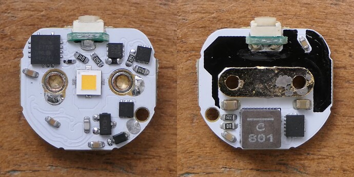
The SC65 driver uses the new TPS61288 boost converter IC from TI instead of the TPS61088 used in previous li-ion boost models (SC63/64, H/SC600 III/IV, SC700). it has lower resistance MOSFETs (6.5/8.5mΩ vs 11/13mΩ) and a 500kHz switching frequency which should allow higher peak and max current efficiency.
The inductor as been upgraded to a larger XAL5030 with lower resistance, although it’s a 0.8uH vs the 1uH XEL4020 previously used which should limit efficiency gains a bit as it’s a bit low for 500kHz.
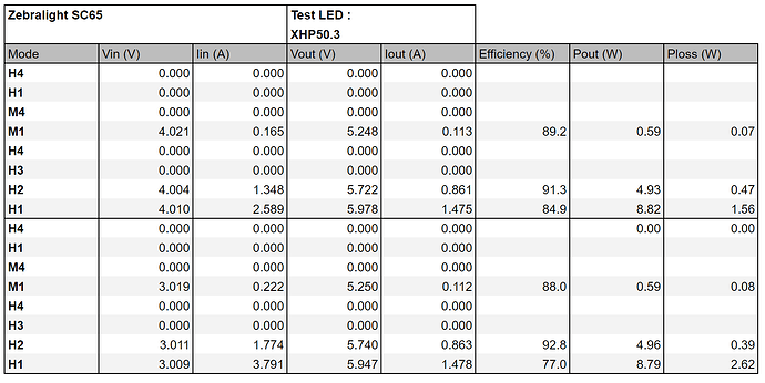
Output and efficiency measurements :
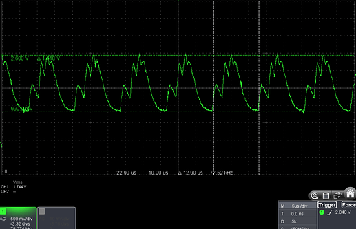
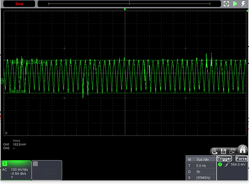
As you can see the table is incomplete, after a few measurements I noticed that the efficiency numbers are too low, so I stopped and tried to find the problem, starting with my testing setup, which I couldn’t find any problem with, then I fired up my oscilloscope to look at the output waveforms :
1.6V peak to peak oscillations at 77kHz at max output, oscillations that big will often tank the efficiency.
Oscillations at high output can be due to not enough input capacitance, the driver doesn’t have much, only a 10uF 0805 MLCC, plus the fact that the driver was powered with a power supply with higher impedance than a cell means that more input capacitance may be needed, but adding a bulk capacitor didn’t change anything, furthermore the problem isn’t just at high output.
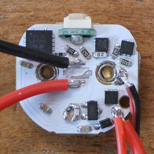
Another reason could be inadequate compensation values for the boost converter, this driver uses verly little output capacitance, thus the values used in the datasheet example schematic, that are often copied directly, could be not suitable. So I looked for the compensation network on the PCB only to see that it was missing 2 of the 3 passives for it (only one cap when 2 caps and a resistor are needed), this is rather strange and as soon I saw this I knew this was the cause of the unstable output.
Fix on the driver after determining the right values :
That solved the problem, 500kHz 260mV P-P ripple at max output, exactly what we should be seeing :
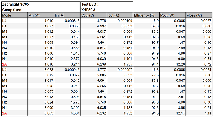
And the efficiency measurements.
Which are more like what we should be seeing with a TPS61288 driver. Bonus 2A measurements in red.
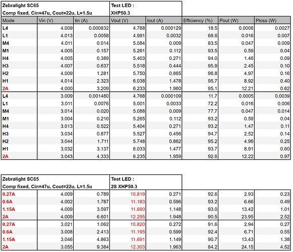
I mentionned that the inductance of 0.8uH may be a bit low, so here are measurements with a 1.5uH inductor, I also measured 12V ouptut, for example with a LED swap to XHP35 :
Although with a higher inductance values, the switching frequency at min output goes lower, making the flickering already present at L4 more visible.
In conclusion this is an upgrade over the previous driver used in the SC63/64, but only if the compensation network is fixed, I messaged Zebralight about this problem after testing it (26 sep, yes that’s a while ago already), they said that they where aware of this problem and that it only affected the first production batch, the next ones in 3 weeks time (that would be 17 oct) should be fixed as they “found out a better way to route the PCB”, kind of weird they went with this for the first batch though.
