Great idea! I’ll take that with SBT90.2 ![]()
Hello all,
Fellow BLF member Thujone recently purchased a Noctigon K9.3. Unfortunately he did a little experiment with water and it led to a partly working K9.3. See here: https://budgetlightforum.com/t/-/65140
By the time I read the thread, Thujone had tried a bunch of things and had resigned to this flashlight no-longer being functional. I felt a little sad that this nice flashlight would become a paperweight, so I dropped him a message and offered to take a look at it to see what was going on. I had suspected that it was water still being in the switch (or some sort of contamination), and generally that's what I found.
Since I took the flashlight apart, I thought people might be interested to see what's inside, so here's what I found:
================= (reproduced from the other thread) ===================
Had some time this weekend, so I took apart the Noctigon K9.3 which I got from Tujone to see what was the main cause of the button /water issue.
In summary - it appears that water must have got into the dome switch of the K9.3. The switch is a standard SMT low-profile dome switch with a plastic surround, and it appeared to be potted with some sort of water-proofing compound around the edges. I was able to (mostly) fix the problem by baking the switch for half an hour in a reflow oven. It's much better now, but still a little finicky sometimes, so likely the switch had some contamination from the water + dissolved things. The driver and LEDs were fine.
With the K9.3 in hand, I thought I'd do some comparisons with existing flashlights that I currently have. Specifically, I wanted to compare it with the Fireflies E12R, as they appear to be similar and lots of people appear to have questions.
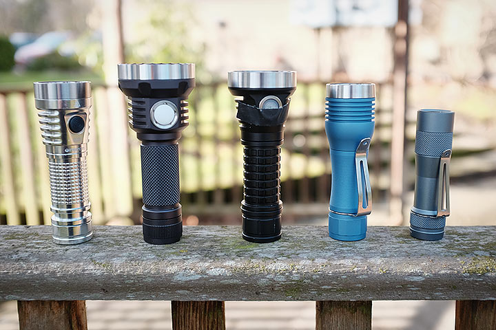
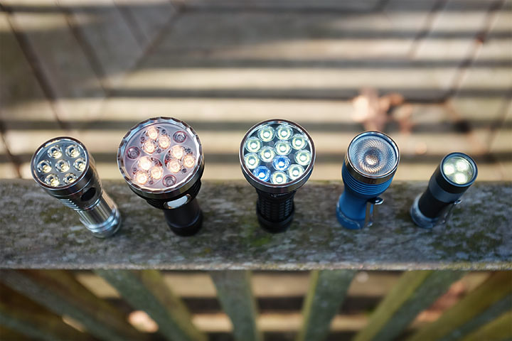
From left to right, Fireflies E07, Noctigon K9.3, Fireflies E12R (prototype), Noctigon KR-1, Lumintop FW3A. The left three are 21700 flashlights. Note - my E12R is a prototype and I put a piece of tape on the switch because I haven't pressed the switch ring in yet (and it is loose). If you didn't know, I was asked by Fireflies to design the driver for the E12R to their specifications, so I will refrain on commenting on its performance as I'm not impartial. However, I'd like to talk a bit about the machining and design, which I had no input on.
On paper, the K9.3 is only slightly bigger and heavier than the E12R, but it actually feels substantially larger in the hand, and is definitely on the heavier/bigger side for an EDC, even for a big jacket pocket. In the hand, the E12R feels really nicely balanced and the 'trombone' shape actually helps it fit in the hand well. In comparison, the K9.3 feels very front heavy (there's a LOT of metal in the head, as I will describe soon), and the center of balance is somewhere near the E-switch! However, the heft does make it feel like a premium product, though perhaps it can be a little heavy for EDC.
In terms of finish, both the Noctigon and Fireflies have similar quality of anodizing - they both feel smooth, even, and robust. However, I have to say that I generally prefer the colour of anodizing that Noctigon chooses - the dark grey looks a fair bit more premium than the black of the Fireflies. The scalloped stainless-steel bezel of the K9.3 is also very nice. Finally, I also prefer the texturing of the grip on the K9.3. I suppose this is just personal preference, though.
To summarize:
- K9.3 feels a fair bit bigger and heavier than the E12R
- I prefer the machining, anodizing, and finish of the K9.3
- I prefer the balance and shape of the E12R; K9.3 is very front heavy, ergonomics are not ideal
- I much prefer the switch of the E12R / the white rubber dome of the K9.3 looks a little cheap compared to the rest of the flashlight
For a flashlight of this formfactor, I'd like the shape and size of the E12R combined with the machining finish and anodization of the K9.3.
It's time to disassemble. The K9.3 I received from Thujone was misbehaving and the switch was extremely sensitive and inconsistent.
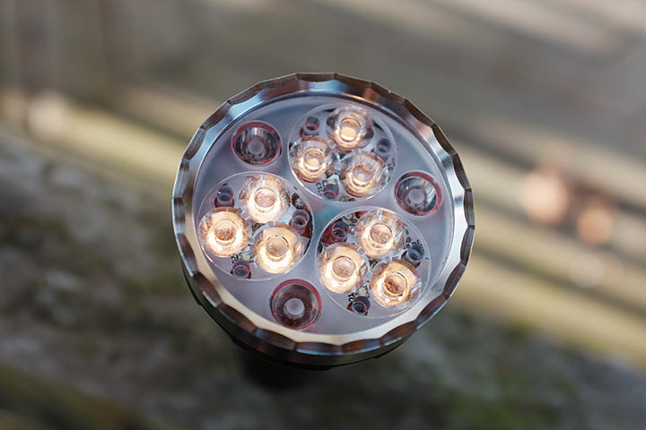
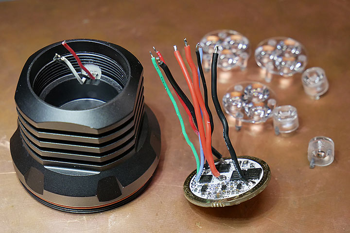
First was to remove the optics. This comes apart very easily. You can see that the K9.3 actually uses three triple optics plus three single optics. They are positioned and held in place with a nice frosted plastic spacer. This is topped by a large 49.5mm diameter 2.5mm thick AR-coated glass lens, held in placed by the scalloped stainless-steel bezel ring, and two red O-rings. It's nice to see a quality-looking glass, but it definitely contributes significantly to the front-heaviness of the flashlight. I'd like to see perhaps a thinner 1mm ion-treated lens instead, like gorilla glass (what Zebralight uses for the SC700d).
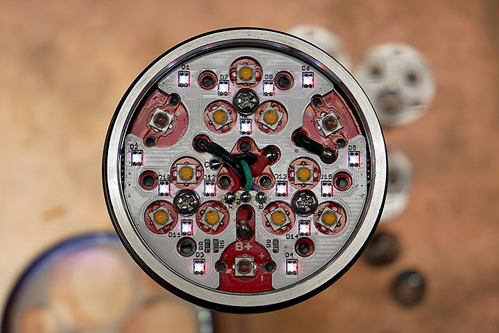
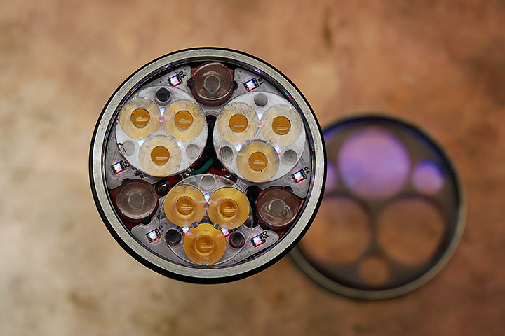
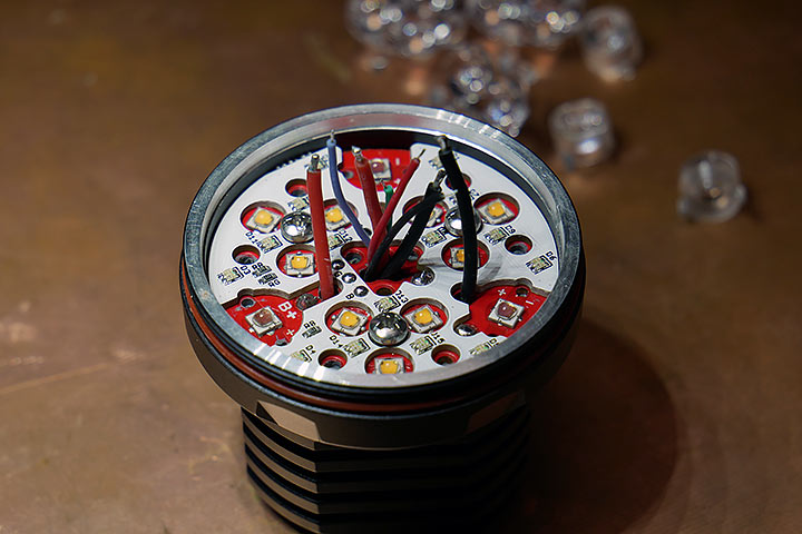
Out comes the optics and you can see the white aux-led PCB with 15 RGB LEDs, along with (in this case) nine 2700K SST20 emitters and nine red emitters. A total of 8 wires are needed for this - four for the two main LED channels and 4 for the aux LEDs.
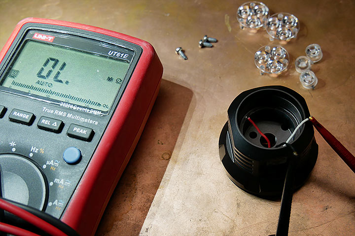
I had to disassemble the flashlight to get to the switch PCB and to remove it. As I had expected, the driver tested out fine, but the switch PCB was the issue. I found that with the slightest pressure on the switch, the switch resistance didn't drop to zero but hovered inconsistently around the few hundred ohms range. This indicated to me that most likely there was some contamination inside the switch itself, i.e. water got in and stayed there.
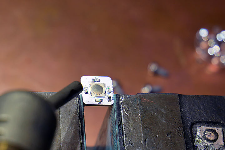
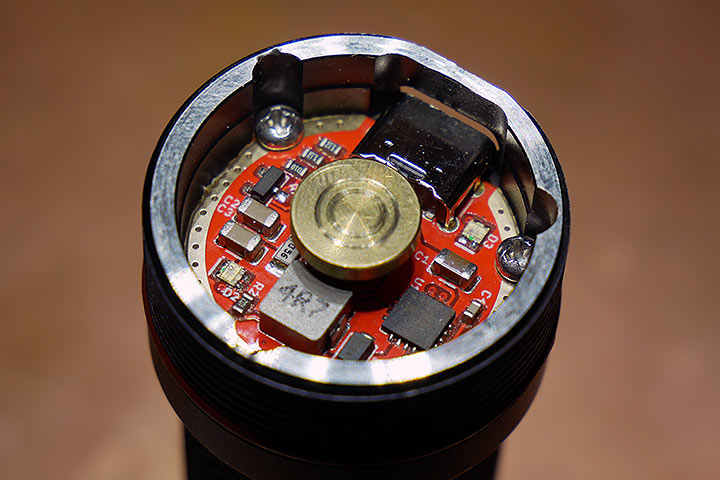
Here's the switch PCB removed, with the dome switch. You may be able to make out some conformal coating around the switch - it looks like it was there to prevent water from getting into the switch, but unfortunately, water seemed to get in, and the coating made it stay there. I tried blowing hot air on the switch for a while but it didn't solve the problem. Ideally I would replace the switch, but I can't get parts quickly, so I decided to throw it in the reflow oven and I baked it at 150C for about half an hour, placing it sideways.
While doing this, I had some time to take a look at the driver. It's a pretty simple design- two Constant Current Linear Channels, each up to 8.95A, one of which has a turbo FET direct drive (for the 9 LEDs).
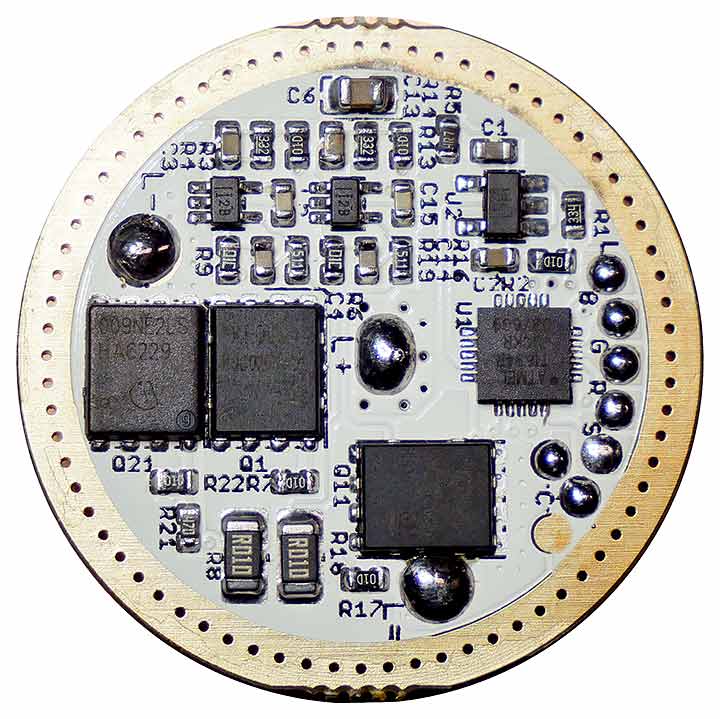
The main MCU is the standard ATtiny1634. There is aux RGB LED support, as well as a external LED for the switch. Power is provided via a 2.8V regulator. Sense resistors are 1206 10mR resistors, and the feedback loop for each CC stage is handled via a TLV333 op-amp, using a Mosfet as a linear pass element. The driver is 29.9mm OD with a 2.6mm ground ring around both top and bottom, with a 11mm spring pad for the battery-side. PCB measures 1.6mm thick.
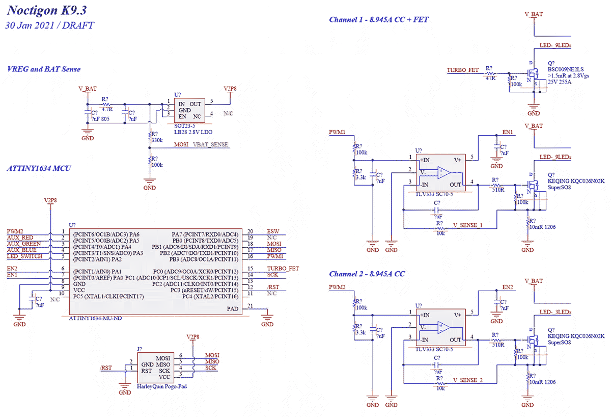
I drew a rough schematic of it, pretty standard implementation. Control is done via the standard OC1A/B 10bit PWM at 3.9kHz. It's filtered through a RC LPF and acts as the reference voltage for each linear constant current stage using a Mosfet as a pass element. Simple and effective, but fairly inefficient as well. It's one step up from the AMC7135 regulators since brightness control is now PWM-free, but the downside is that it still regulates and burns excess energy as pure heat (i.e. the pass element acts as a resistor).
One thing about the K9.3 design is that there is a huge driver cavity, which makes sense since there needs to be a lot of wires (as you can see above), and it would be difficult to assemble if the cavity was shallower. The driver cavity measures 25.4mm in diameter and 10mm deep - this makes for excellent modding potential, with the drawback being that the MCPCB is custom, so it's difficult to use different emitters of different sizes. In addition, I found that the LED shelf is a whopping 8mm thick!! No wonder the front of this flashlight is so heavy! There is a lot of metal here.
For those keeping track, the main LED MCPCB is 45mm in diameter.
With the switch out of the oven, I found that it was finally working decently again. Not perfect, but it's possible that the water submersion dissolved contaminants around and in the switch; while most of the water should be baked off, the contacts are likely slightly contaminated still, and the switch is no longer perfect. But it's much better than before. So I assembled everything back together. The most difficult was getting all those wires through the holes. It took a bit of patience, and help with needle tweezers to get this done.
Problem mostly solved for now (I'm going to ask Hank what switch he used or if he can ship over a new switch PCB, since the switch is still slightly finicky), or if I have time I can dig around digikey to find a better replacement).
So.. what about the charger? The charger is integrated in the body-part of the flashlight, on the top of the battery. Again, this adds some additional weight and mass to the top of the flashlight, making it very front-heavy. However, this also makes the flashlight theoretically more waterproof than the E12R, which just uses a rubber flap.
The charging electronics are covered by a press-fit white plastic spacer, which I removed easily. The charger circuit is essentially a datasheet-recommended implementation of the TP5000 2A charger IC. https://www.rzxpoweric.com/data/upload/image/20190515/1557926480137873.pdf The CC USB C lines are terminated with 5.1k, so this should work with most USB C - USB C chargers.
Finally, one thing I noticed... this flashlight has no reverse polarity protection. I didn't see any on the main driver PCB... and I only tested this after I had re-assembled the flashlight, so I haven't been able to do a detailed analysis. It appears that there is some reverse current flow (my guess is that it's through the LDO, which also may cause reverse current through other ICs). The LDO has a marking LB28 L7F1, so while I initially guessed it is the MIC5025, the markings don't quite match, and the MIC5025 does have RCB (it is a footprint compatible part though). So just a note, do not insert the battery backwards in the K9.3, or there may be magic smoke coming out.
I tested this quickly with a bench supply with CC mode, and sure enough it seemed almost a short when plugged in backwards (there is a V_fwd drop which looks like some diode forward voltage). I thought that perhaps there would be some RPP in the charger PCB but it looks like there isn't, though the charger IC itself has RCP internally so it shouldn't be affected. Note that I haven't looked at this in detail so perhaps I missed something, and I only tested this at a low 2V.
As for why would water get in - the entire flashlight seems fairly well designed. Two large o-rings prevent water ingress from the front - adding silicone grease should help in general water tightness. The main body threads also have an o-ring each, and appear to be decent quality. The switch is held in place via a rubber dome, squeezed in via a switch ring - that needs to be screwed in tight for water-tightness, so perhaps Tujone's one had a leak somewhere around the switch dome, and water got in?
Overall - my thoughts on the K9.3 are a little mixed. I am impressed as usual, with the workmanship and machining, as well as the large amount of engineering that clearly went into the entire design, from the charger in the body tube, to the complicated MCPCB / Aux PCB / Optic combo.
However, I felt that this created a somewhat... inelegant design, and the overall package was a little.. big. The flashlight is a little too front-heavy, affecting ergonomics. The 9+3 LED design looks interesting but the choice of optics leads to an unnecessarily large head (the E12R also has 12 LEDs but is a fair bit smaller). The head is well machined, but it has a driver that I think could be improved to take advantage of all the space. This flashlight also has a comparatively large number of components both mechanical, optical, and electrical, leading to a complicated and time-consuming assembly (including the soldering). For a 21700 flashlight, is also very big compared to say a Fireflies E07, Lumintop FW21, or even a Zebralight SC700d (much much smaller!).
Thanks for reading!
Really nice and interesting analysis, thank you, loneoceans. The driver efficiency is indeed a bit low, especially when an emitter of lower Vf is used. The wasted energy and extra heat generated are really unfavorable, IMO.
Is that the reason why my K9.3 with 3x SST20-DR in CH2 steps down immediately from turbo mode? I can see a brief increase in brightness when doubleclicking from ceiling brightness to turbo but it drops immediately back to ceiling. The flashlight‘s head will not even get warm when doing this 2-3 times in a row.
I just tested Thujone's sample (with a fresh Samsung 30T), and CH2 with the SST20-DR - I see the same behavior.
Looking at the firmware, specifically the cfg file, (https://bazaar.launchpad.net/~toykeeper/flashlight-firmware/anduril2/view/head:/ToyKeeper/spaghetti-monster/anduril/cfg-noctigon-k9.3.h) I see that the top of the ramp should be level 120. Double clicking, I get to level 150 for a short while (less than half a second) before it drops down. I'm not quite sure why either since like you said, the flashlight is not even warm, and a tempcheck (reading the temperature from the Attiny) shows that temperature is not even close to the limit. So perhaps something else is going on (not thermal limitations, at least it doesn't seem like for this specific scenario).
Thanks a lot for doublechecking this issue, loneoceans. And thanks for this very interesting analysis of the K9.3 components. On Hank‘s thread there was some interesting discussion of why deep red LEDs could be stepping down so quickly in the K9.3...
https://budgetlightforum.com/t/-/57210/2602
I must admit I am not skilled enough to understand everything in detail. :-))
I wonder if Jacky were to offer a „deep red“ E12R with your (customized) Lume1 driver. 12x SST20-DR should hopefully sustain direct drive, even with a Samsung 30T. If I calculate 3A max per LED times 12 LEDs I get to 36A for the entire setup.
I believe that’s because the Vf of SST-20-DR is simply too high when driven by 3A per emitter. My KR1 with XP-L HI also regulates poorly at Turbo because its Vf is higher than 3.8V at 5A.
Well, if you look the delta Vf vs current graph of the SST20 deep red, it is quite clear…

Note that 0,00 is typically 2,3V at 700mA.
So if you do the math, you will see that from around 2A to 6A the power dissipated in the mosfet is almost the same and at maximum. This is just the wrong driver for this LED. If he MCU gets hot at 9A and starts to regulate, that’s when it’s getting even hotter. So either way, it would make sense to go directly to a very low current without even passing 2A-6A…
It’s especially bad for the SST20 deep red, but not only that.
Ask yourself why Neven (Led4power) always recommended to use his Mosled boards (so that the mosfet is next to the LEDs and not on the driver next to the MCU) when bulding triples and quads, even with his first driver LD1 which was 5A I think. Now you have 9 LEDs in parallel at 9A and the mosfet burning all the power next to the MCU and the battery.
That’s strange Lux… I haven’t noticed that using a 30T cell on either of my 9.3’s that have CH2 deep red
Man I wish I’d not gotten Osram yellow on my 9.3 that has E21A 2700K on CH1. Green would’ve been sweet or something cooler like the last build you got
I assume you did not change anything on the ramp configuration and batteries were fully charged, right?
Can you please ramp up your both K9.3 on CH2 to CEILING (120/150) and then carry out a doubleclick to go to full turbo (150/150)? Best would be to direct the beam to a white wall in a dark room. Please observe the brightness change when going to turbo level. As reported before, my K9.3 gets noticeably brighter for a blink of an eye and immediately reverts back to CEILING (120/150) again. Since loneoceans reported a similar behavior on the repaired K9.3 with SST20-DR, it would be interesting to know if your lights act differently or the same way.
IIRC, the Flashoholic reported in his video review that his SST20 2700K 95CRI on CH2 stepped down after 15 seconds. They maybe have a higher Vf than SST20-DR 660nm and cause less excess heat with the linear driver?
In any case, I am a bit surprised how quickly CH2 steps down even if the thermal threshold is set to 65°C or higher. I wonder if Andúril 2 needs some more tweaks (e.g. thermal config separately for CH1+CH2) or if everything can be justified with the basic principle how linear drivers work with low voltage emitters.
Hey Lux, yep mine is factory default. I just tossed a fresh 30Q and did your test and I think you’re right. It does seem to go down to the ceiling max after a short time on turbo. It’s rather subtle and a little hard to judge it because my eyes are adjusting to the burst of red light in the dark room. I need to buy a nice device for measuring flashlight brightness
Yeah, judging is indeed a bit harder with deep red light. It felt a bit weird to my eyes to look at this intense spot going from ceiling to turbo. It appeared like a short flash.
Interesting side effect of looking at deep red light: Color perception will be altered, i.e. standard red (620nm) will look like amber/orange but not like red anymore. Fortunately, the effect is not permanent.
I have a Sofirn flashlight (with AA battery), for which I replaced the original XP-G2 emitter to a cheap board fitted XP-E far red. I had the chance to compare the color perception to SST-20 deep red, and I found, that even SST-20 deep red (~660nm) looks a little bit pale compared to the ~730nm far red - but the difference is very subtle without putting them side to side. Difference to ~620-625nm red is much more noticeable. Still, it would be lovely to use a multi-emitter far red flashlight (that comes only in SST-10).
Would it be more reasonable to use a LiFePO₄ battery with linear drivers and low-voltage emitters like SST20-DR or Osram W1/W2? The excess voltage should theoretically be lower as the battery‘s input voltage will not exceed 3.6V, thus less heat to dissipate from Mosfet and MCU.
I shared the same thought as you and did some experiments when the Emisar D4 and D4S were out. FET, 7135, and linear regulation drivers all wasted too much energy and turned that into too much excessive heat unnecessarily. However the results of IFR’s on D4/D4S were not quite impressive, because the LiFePO (IFR/LFP) batteries have not much energy.

NOTE: That A123 cell is actually manufactured by LISHEN, not A123 itself. The quality of the Soshine IFR cell varies noticeably from batch to batch, the one used was from the best batch I got.

NOTE: That K2 Energy cell is actually manufactured by PLB, not K2 Energy itself. The PLB 35A cell actually has more capacity and higher voltage under the same load. You may consider the K2 one as a degraded PLB 35A.
But I do prefer using an IFR in my Noctigon KR1’s (CSLNM1/CSLPM1) as long as the runtime is not a real concern, because the Vf of these emitters are so low that the wasted energy and excessive heat are not acceptable at all, though it’s a good pocket thrower. An IFR 18650 can effectively reduce the heat, though the max brightness and runtime are reduced. I’m looking forward to the Fireflies T1R (using the same 6A buck driver as E12R too) to replace the KR1.


I intentionally off-calibrated the temperature sensor of the tested lights so that no thermal step-down could happen. The huge decrease in brightness with the 3.7V li-ion was because of heat (and LVP in the end, of course). For the IFR cells, the drop of brightness in the very beginning was expected, simply their discharge characteristics.
Also I would like to share with you my runtime measurements with my K9.3. In most of the experiments, I intentionally off-calibrated the temperature sensor of the tested lights so that no thermal step-down could happen. But I did calibrate the temperature sensor correctly before conducting experiments for the purple curves (with temperature limit = 50°C) to see the stable brightness range under my room temperature condition (~22°C).
Don’t take the lumen numbers seriously, they are simply rough estimations. I cannot estimate the lumen numbers for the deep-red/yellow emitters since I have no corresponding reference lights, so I only show the relative output here.


The efficiency of the linear driver is not quite impressive ![]()


The red curve (Turbo) cannot be regulated, meaning that the Vf of the emitter is simply too high.


It’s interesting to see that the red curve (Turbo) performs noticeably worse than the orange curve (Step 7) here. The extra current doesn’t give any visible increase in output, simply more heat. That’s why the purple curve looks even better than the red curve in the first 2 mins, because it steps down and decreases the current.

The cell voltage is 4.186V after charging.
This is amazing. Thanks for sharing this info
Sorry Photon Master, I don’t mean to bug you, but did you really have to quote the whole picture heavy comment just to say thanks to him? (Anyway, thanks to him for sharing his measurements as well.)
Oops thanks that was stupid. I fixed it
Wow this is a very detail tests, thank you toobadorz for making all the experiments and charts! I saw that you did same test with Fireflies E12R on here:
https://budgetlightforum.com/t/-/64022/349
From what I can see to compare, using same Samsung 50S battery:
Noctigon K9.3 with E21A 3500K D220 R9080
- 420 to 600 lumen for 2h32m (auto regulate)
- 190 lumen for 7h 30m (cooled)
- Charger 2h 53m
Fireflies E12R with 219B 4500K D220 R9080
- 1500 lumen for 1h 08m
- 900-800 lumen for 2h 07m (auto regulate)
- 800 lumen for 2h 22m (cooled)
- 225 lumen for 7h 0m (cooled)
- Charger 3h 01m
Efficiency
I do not know the efficiency different between 219B and E21A, but it look like the E12R driver is much more efficient. From 50C no cooling test for both (I think flashlight settle at thermal stability after a while), the K9.3 go down to 420 lumen first when it is hot, then as battery voltage drop, my guess is driver is more efficient and heat less, so the brightness goes to 600 lumen until it turns off at 2h32m. The E12R somehow can stabilize at 900 to 800 lumen, about 2x to 1.5x brighter, and last for 2h 07m, shorter than K9.3 but much brighter. If I assume current is propotional to lumen within small range, then K9.3 is 77520 lumen*min, and E12R = 107950 lumen*min, so E12R driver is almost 40% more efficient (assume led is similar efficiency)?! Maybe my maths is wrong?
Charging
First it look like K9.3 charge about 10m faster than E12, but I notice that while max charge current is higher on E12R, it starts with low charge current for first 27m, before going to 1.9A max. Compare to K9.3 which start at 1.4A at max at 1.7A. Why is the charger doing this? I made some research and I found this: https://www.digikey.com/en/articles/a-designer-guide-fast-lithium-ion-battery-charging. Maybe E12R is charging the battery at low current from 2.8V to 3.0V for battery health before fast charging. I think this means that it may be good for health of lithium battery, but if your battery is 2.8V and you want to charge fast, the first part will be slow.