[ENDED] Group Buy: 46mm BLF SRK 7135 V2 - 32x 7135 Drivers - No Drama!

^ what they said. Very nice soldering on the stacks, nice work with the firmware.

You might consider stars for a mod like this, the star configuration stacks together nicely and allows for the use of larger mcpcbs. :wink: Lead pads are also usually in a better configuration. Still, looks like you’re getting really close to the desired result, sucks that the 22ga leads had to be used up top, 20’s would be nice, perhaps a 20ga Teflon lead coming off the emitters? The 20ga Teflon is usually even slimmer than 22ga Silicone. Then you could use 20 or 18ga inside the pill to deliver to the short through-shelf of the Teflons.

Yea, was considering teflon, but they are sooo stiff. If I reflowed the Noctigons down, then teflon would have been a good choice. I got Teflon in all common sizes now.

Think'n bout reflowing MCPCB's on lights like this, seriously thought if I could set the solder paste under the MCPCB's, then use dabs of thermal epoxy on the edges of the MCPCB's, then lock the positions in with the reflector and centering pieces in, tightening up the reflector screws (I replaced the stock ones with better, longer ones already). Once the epoxy hardens, dis-assemble the reflector, remove the centering pieces, then torch heat below the plate to set the MCPCB's solder paste. I think the epoxy would not make a mess, or burn or something. The copper plate is actually two rounds reflowed together to get the desired thickness, so might risk they will come apart and sliding, unless maybe setting the screws in place to keep them aligned.

Dunno if that would work well, just might. Think if I torch heated the plate with the reflector and centering pieces in, the centering pieces would probably melt.

What actually worked out well with this "Fing" light was there was a lower, slightly narrow shelf lip/edge in the housing, so I could use that with using a thicker copper plate. If I had to work at the same height of the stock big 5 LED MCPCB, would have had to use something very thin, or in 2 stages in diameter, if you know what I mean. Again, without the luxury of being able to machine things out.

Just can't imagine doing a 7, 8, or 10 LED SRK light like this... Wiring alone would be insane.

Bypass the wiring. Seriously.

Arrange the mcpcb’s so that you can access the common pad and cut a thin sheet of copper to fit over matching pads, then run a single wire up through the shelf to attach to the sheet. It’s thinner, carries ample current, and produces a neat result while maintaining the current flow we desire. :wink:

Think I need a visual , but kind of/sort of think what you mean. Did you ever do something like this before? Definitely hard to visual this, and maybe can be done in multiple segments, not just one '+' template and one '-' template, if I understand this.

I’ve done it with quads in a small light, works like a charm. And yes, you could do a couple of groups if it made it easier to work pos plate around neg. It prevents having excessive wires everywhere and allows a single fat lead for each pole coming up through the shelf. These can come in together or on opposite sides, whatever works.

Hhmm - might work. Certainly lot less wires, then possibly improve voltage drops. I re-wired the tail PCB jumpers using 20 AWG Teflon, and replaced the 18 AWG loop with 16 AWG, but didn’t get any gains.

Crap somehow i missed this GB.

Maybe it’s time to scrutinize all the added chips? You’re missing enough amperage to account for 8 chips, what are the odds it could be that many giving issue? The cells should do it, fairly easily, so it’s either a loss through the wiring or some chips are not activating or both.

I don't think that this driver is a great one to stack chips on unless you've got a ton of voltage overhead, like with red LEDs or something like that. I think that the traces are just too thin to do much more than 32x 7135 in a normal setup without a ton of resistive losses.

Ah, well see? There ya go!

I’m guessing these drivers are no longer available?

You mean these ones?

Ahh - ok. Probably would do better with 219C’s as well, I’d suspect. Thanks Richard, and Dale! I’m still liking the results - 5,000 lumens in a neutral tint (4 3D’s, 1 1C), lasts bout 2 1/2 minutes, standing alone, before getting uncomfortably hot.
My UCLp order should be here by Monday, so should get a nice bump with one installed/ I planned out vertical spacing to accommodate one - it’s thinner than the stock lens.

DBSAR - yes, just not at the group buy discount price. Richard is working on another group buy on a driver, but probably a 17 mm one.

Tom

After reading Toms build I went back and checked my 2 M6 builds one using 48 .38 chips 18.24 amp or 6.08 for 3 XPL-V6 emitters and the other 52 .38 chips or 19.76amps 6.58 for 3 XML-2 U2 0A’s emitters Both read off my Fluke to be around 14-14.8 amps? Checked with my UT210E was way higher? So I checked one of my lights that always reads 8 amps no matter what meter I have used, and this is what I got? First the Fluke… First read off the UT… Second read off the UT… And it repeated several time after this, the same way too high? Any ideas? When I first got it a couple months ago, it was spot on to my Fluke36 now it’s all over the place?/ Any one seen this before I really like this meter too, nice and compact and easier to handle then the Fluke.

I built in a 16 AWG loop in the end cap to accommodate my UT210E, so that's what I used. The springs were wired together, than has a thin jumper wire to the screw mounts, so I replaced the jumper with a 16 AWG loop (I also ran 20 AWG Teflon wires from the bypass wires to one common pad of the jumper wire). The clamp meters are much more reliable at high amps and will be accurately higher than a DMM, but thought someone said you would see about the same readings on 7135 based drivers. Maybe that was just for low amps? Dunno.

Actually on my M6's, I never measured a true tail amp readings. Didn't think there was an easy way - how do you do it?

Edit: Ohhh - the Fluke is a clamp meter, not a regular DMM, sorry didn't catch that til I studied the pic more closely. Weird, that's a bad sign. I think Mitko warned us of quality problems with the UT-210E meters - he went thru 2-3 of them. This is back when the group buy was being considered. I haven't seen problems with mine, yet that is...

I got in my UCLp order the other day, 54.87mm x 2.25mm, and installed/tested in the TangsPower Fing 5X light. A straight before/after on the same cells resulted in a 5.6% bump in lumens. On fully charged cells, lumens increased 7.3% compared to my last best measurement, and throw in kcd got an 8.4% bump. This is all based on @30 seconds, for it's a more stable reading. The kcd bump is a little low, but could be because I'm using a different 1330B meter for throw now, and haven't calibrated it, but thinking it's coming in 1-2% low on throw #'s (it's ~4.35% low in lumens compared to my old 1330B). From past experiences, % bump in kcd is close to or at double the lumens % bump.

Once again, really nice bump at no extra power, just a better lens. It's like getting U4 performance from a U3.

Latest #'s, tail: 14.78A (clamp meter), lumens: 5,525 @start, 5,270 @30 secs, 45 kcd taken at 5 meters (424 meters)

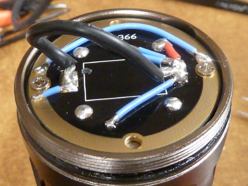
More modding, of course! Just not happy bout not getting the max amps out of all those purty stacked 7135's (thanx btw for the complements!!). So, I upgraded the 20 AWG driver LED wires to 18 AWG, 18 AWG shown here:

Results? Somewhat disappointing, raising tail amps from 14.78A to 15.0A. This justifies what Richard says about the impact of heavier gauge wires - relatively low.

So what next? I am getting 15.0A measured, but theoretically the 7135's should get 18.08A. Well again I refer to Richard's comments. He said the traces on the SRK driver probably can't handle this amount of high amps, and I believe him from looking at it. Well, that's fixable easy enough. Just add some decent jumper wires to supplement the traces. I'm thinking the bottleneck is for the traces of the 7135 outputs to the pad where that big black 18 AWG wire is soldered. So, create a pad right next to it:

And run 26 AWG teflon coated wire jumpers from the outer most 7135's to that pad. Sorry, don't have a pic, but it's 3 wires connected to 3 different stacked 7135 output pins, about evenly spaced to the outer banks. Results?

Ok - recovered almost all those missing amps. New reading (again at full charge SAM 30Q BT's) is 17.6A at start. Here's my tailcap with the built-in 16 AWG loop:

Here's a live reading after the measurements, so it's dropped a little:
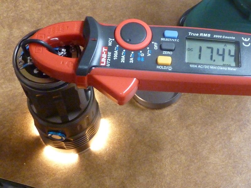
New Measurements:

tail: 17.6A (clamp meter), lumens: 6,222 @start, 5,953 @30 secs, 52 kcd taken at 5 meters (456 meters)

Again, in a pretty nice neutral tint (4 U3 3D's, 1 U4 1C)

I do love this UT210E meter btw... Ohh, and Thanks Again Richard for this No Drama Group Buy!!

Tom. This comment is in no way meant to be offensive but the exact opposite. You are a freak buddy. What you come up with and your abilities to enact what you think of is beyond reproach. Orsm work and executed perfectly. Nough said. :beer:

^ what he said, I just can’t get “Orsm” to roll off my Texas twang. :wink:

Dale. Your another one. Freak that is. :smiley:
ORSM as in awesome. Tis easy.