How the size/shape of a secondary optic (reflector, TIR, lens, etc.) affects the beam profile and throw generated by a flashlight is a question that comes up fairly often. Unfortunately, I have not been able to find a comprehensive answer to this question that is both easy to comprehend by a nontechnical audience, and factually correct. Bits of the knowledge are scattered across different places, or simply exist as folklore among those familiar with some physics…
…until now! I stumbled across this TLF post that answers this question in a comprehensive but very accessible way, requiring just some thought experiments to understand what’s going on, no mathematical heavylifting. In particular, it establishes the dependence of throw on a reflector’s frontal area, and dispels the misunderstanding that a deeper reflector focuses nontrivially better than a shallow reflector of equivalent diameter.
Here’s the post in German: Von was hängen eigentlich die Lux ab (Throw) | Taschenlampen Forum
Below is a Google-translated copy, lightly reformatted for readability. I have reviewed the translated copy for technical accuracy, and find it satisfactory.
What exactly determines the maximum illuminance (“throw”) of a light fixture?
This question comes up occasionally, but reliably. And then various, sometimes contradictory, opinions or even experiences are shared. I think this deserves a detailed explanation.
Background
Related questions:
- What influence do the diameter and focal length of the reflector/lens have on the beam pattern?
With reflectors, however, the focal length is never specified, and unfortunately, it’s almost impossible to determine it yourself. - …so, less precisely: What influence does the “depth” of a reflector have?
- Regarding lenses: What effect does a second “collimator lens” have?
Some of this (what throw is and what it depends on) is very nicely summarized (in English) by DrJones.
I’ll elaborate further here. And even though physical relationships are essential at the heart of the matter (otherwise it would just be rambling), this text should also be interesting for those not concerned with physical laws or even formulas.
Just a quick refresher: How exactly do lux and lumens relate?
Lux only indicate how brightly a specific spot is illuminated.
Lumens indicate how much light emitted from the lamp overall, regardless of where it goes.
A good analogy is a stream of water, for example, from a garden hose:
- Lumens correspond to how much water flows per second (somewhere).
- Lux corresponds to how far the water stream travels.
These can be completely independent of each other: A huge amount of water can slowly gush from a thick fire hose,
while a small water pistol can reach a great distance. I won’t stretch the analogy any further, though.
Contents:
Part 1 - Maximum illuminance, the highest brightness in the spot.
This section deals with the “lux” that a light source achieves.
What factors determine this brightness? In short, these are:
- the (viewed from the target) seemingly illuminated area of the reflector/lens.
- the luminance in this area - and thus that of the source (also called “surface brightness”).
Interestingly, however, they do not include:
- the focal length
- or, in the case of a reflector, the depth.
These are the most common misunderstandings on this topic (and incidentally, also the reason for this text).
Now, let’s go into more detail:
a.) Apparently illuminated area
Only the apparent illuminated area of the reflector/lens, viewed from the location of the light source, counts.
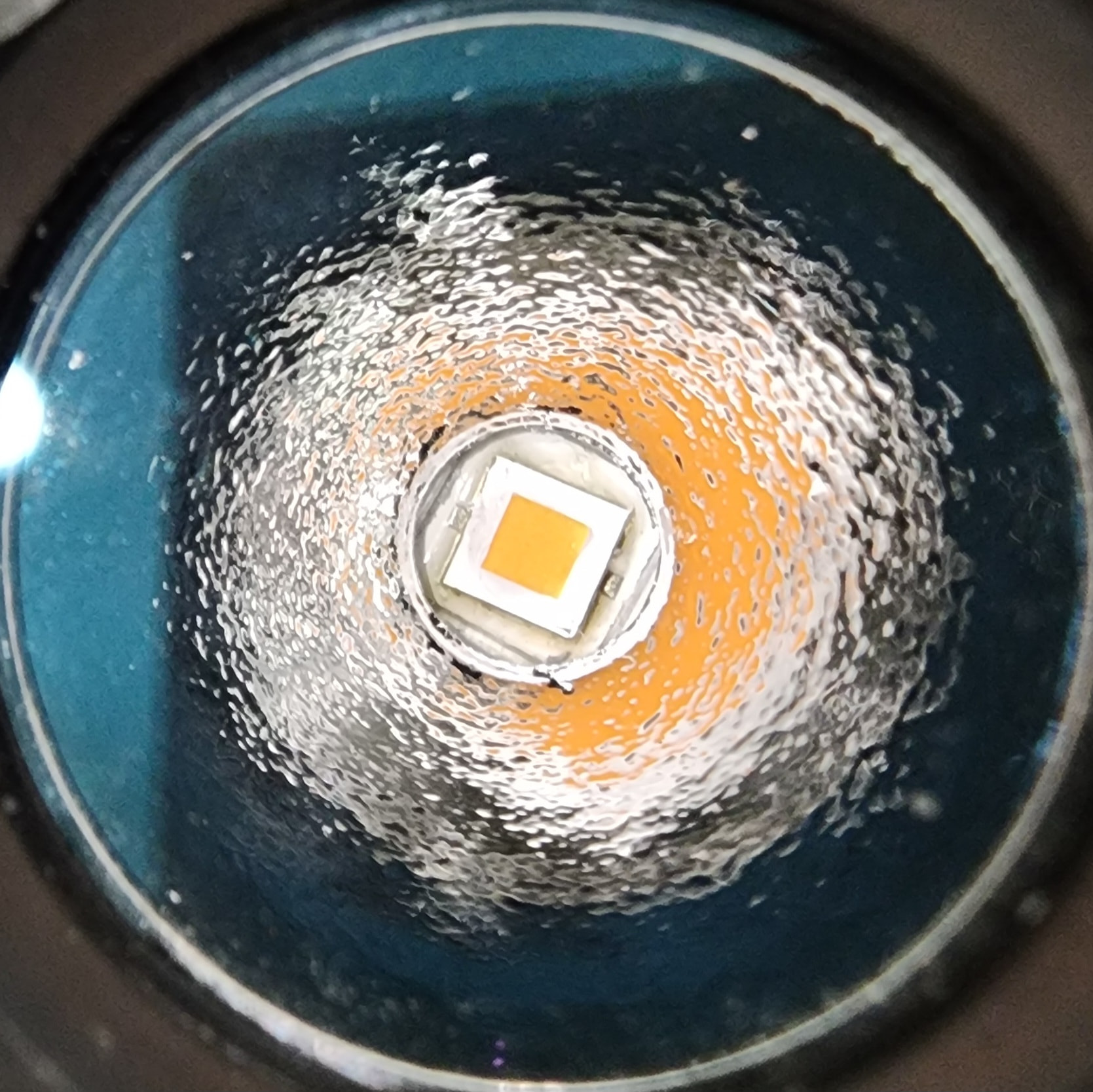
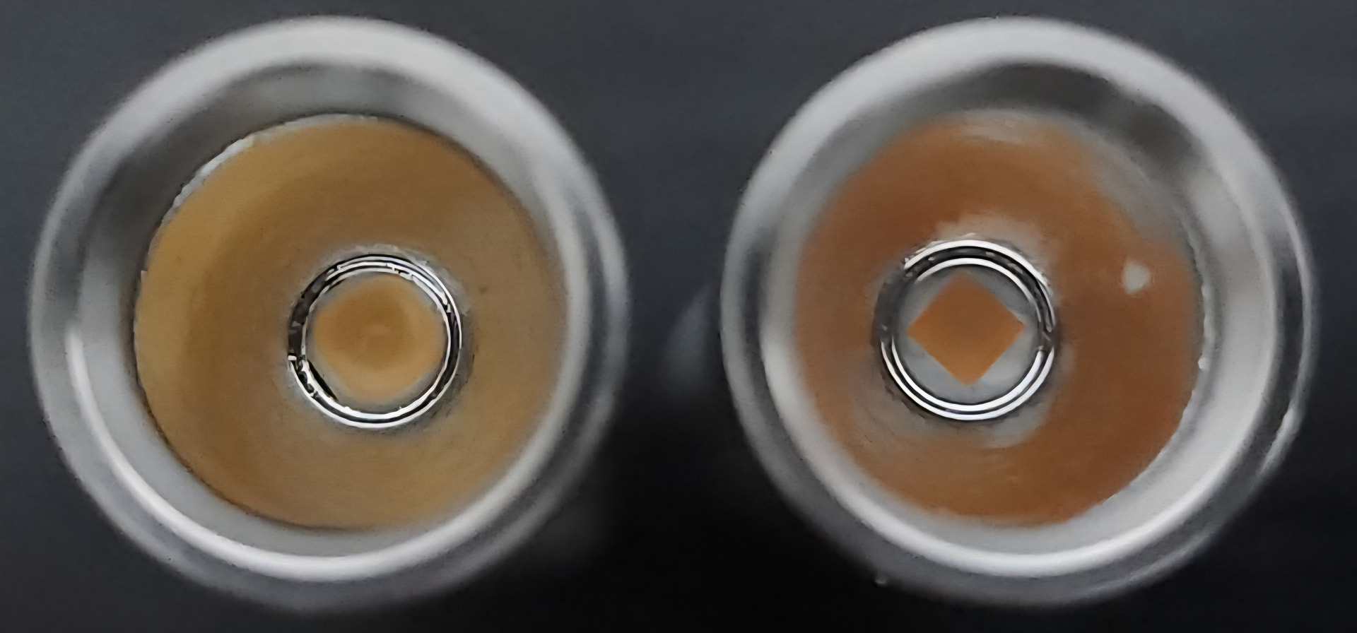
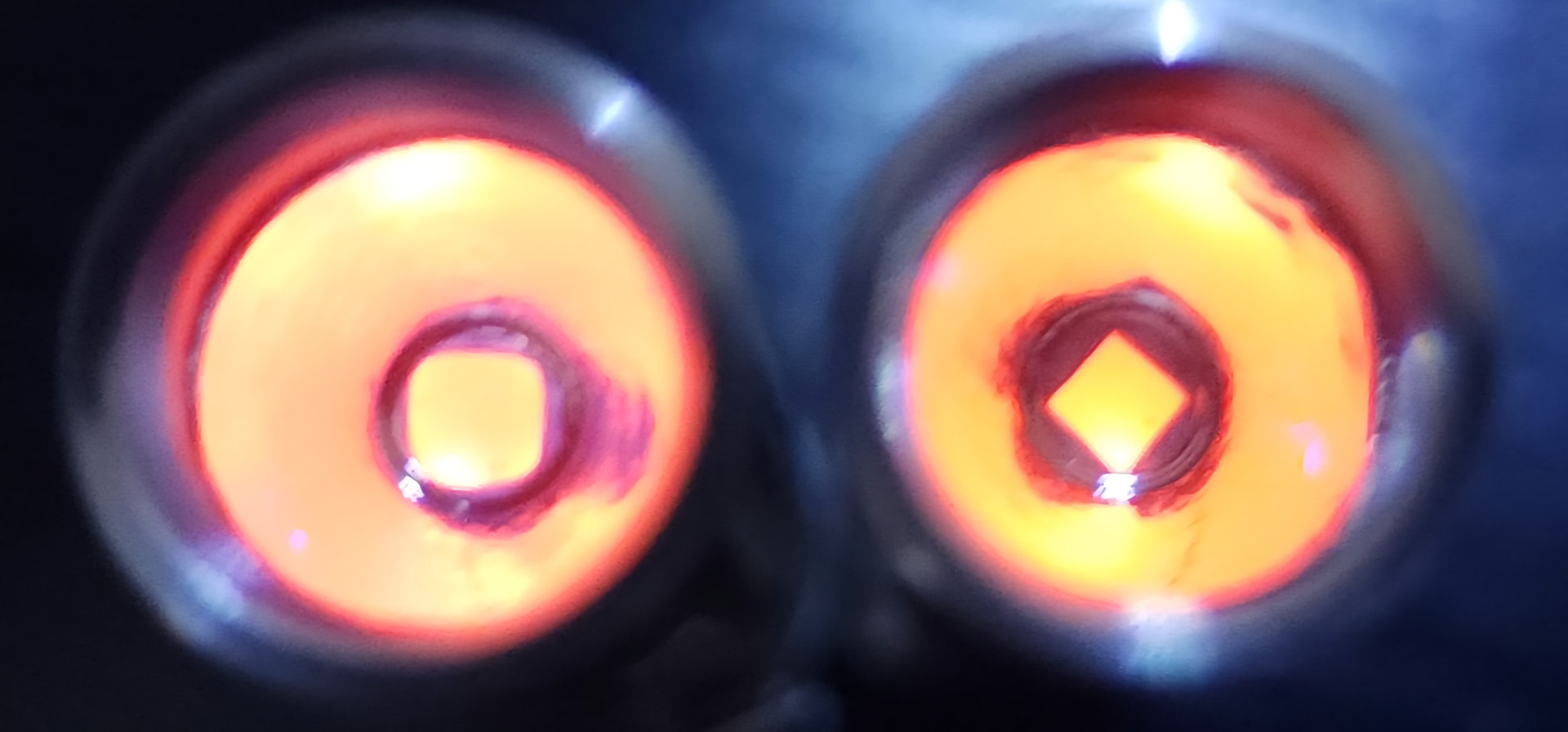
This article contains a few slightly outdated images that illustrate what is meant. You can see quite a few spots and holes that you wouldn’t expect. Normally, you can’t see inside.
In case of doubt, the only way to assess this and find errors is to go to the location of the light source and check it yourself from that point. You can see this area with your own eye if the lamp can be set to a very dim setting, or if you look through a solar filter or welding glass. Or if you can take an extremely underexposed photograph.
The illumination can be highly dependent on the quality of the reflector/lens curve. With larger diameters or tiny light sources, the wheat is quickly separated from the chaff. With small LED drop-ins, however, this question practically never arises.
Simple “spherical” lenses (sphere-like surfaces) can suffice, but quickly reach their limits. For small light sources, only an “aspherical” lens can guarantee complete illumination in certain cases, unless an additional collimator lens is used (see below).
With a reflector, a textured surface (“orange peel”) can cause the area to appear unevenly illuminated, with a “crumbly” appearance.
And it goes without saying that the reflector/lens and light source must be correctly aligned.
The determining factor for the seemingly illuminated area is, of course, the diameter. Since the area is quadratically related to the diameter, doubling the diameter results in a fourfold increase in lux.
With reflectors, the dark area in the center of the reflector must also be subtracted. And even if the central hole in reflectors sometimes appears prominent, it is hardly significant in most cases. For example: The SR90 reflector has an effective outer diameter of 88 mm and a central bore of 28 mm. While this is almost a third of the diameter, only 10% of the total area is lost. Such a loss is barely perceptible to the eye. However, with the overall diameter, even small differences lead to significant effects.
b.) Luminance
This is the very intuitive measure of how bright a section of a surface appears to us.
A white area on the screen simply appears brighter than a gray area. Even if the gray area is much larger than the white one (and emits more lumens overall), it will never appear white to us; it will always remain gray. (Unless an optical illusion is involved… compare “squares A and B”. [image]
The spot brightness is proportional to this luminance. Double the luminance results in double the spot brightness.
Now comes a fascinating property of luminance: This luminance does not
change due to reflection in the reflector or refraction by a lens .
(There is also a physical conservation law for this, keyword “étendue”).
However, reflection/refraction also results in losses. In reality, it is always slightly reduced. But: It can never be “increased” by a clever lens/reflector design!
This leads to the following phenomenon: Seen from the spot, the illuminated reflector/lens surface appears to have approximately the same luminance as the source itself. This is the same situation as if there were no reflector/lens at all, but one were simply being illuminated by a huge surface with this luminance. This is also the reason why, to calculate the lux at the center of the spot, only the diameter and the luminance are needed. the source (including a flat rate for the inevitable losses in glass and mirrors).
Other specifications such as the size of the light source (e.g., LED) and the luminous flux (lumens) are not directly meaningful. At most, they can be indirectly related to the luminance, but are never the sole factor. If one still wants to consider them, then all other factors must also be known.
- With the same current or lumens, a small LED will naturally be brighter, but not every smaller LED is necessarily bright.
- With the same LED, but only then, more lumens also mean a higher luminance.
Small LEDs are interesting for another reason. They generate less heat overall, so this can be dissipated more effectively by the surface underneath. However, the hotter the LED gets, the lower the luminous efficacy. Well-cooled LEDs are therefore essential if one wants to achieve high luminance.
c.) Losses
Losses occur on the path from the light source through a reflector/lens.
With glass and plastic, this essentially depends on whether and how the surfaces are anti-reflective (also called “coating” or in English “AR / anti-reflective coating”).
The degree of polishing or the smoothness of the vapor-deposited coating plays a role in the reflector’s performance. The metals used have different reflectivity values, and even mirrors can, in rare cases, be coated in such a way as to improve their reflection.
Rules of thumb: 4% loss per uncoated lens or front glass surface. Only the highest quality coatings achieve 1%; typically, it’s at least 2%. Reflectors vapor-deposited with aluminum have a loss of at least 10-15%, rhodium at least 20%.
It is also possible to improve the reflection of metals with a vapor-deposited coating (see, for example , “AQ HR” at the end here ), but this is not worthwhile for our purposes.
d.) Why doesn't the focal length matter?
Question:
" If a reflector is deeper, then it captures more light, which it can concentrate. Then the spot must also be brighter! "
or:
" Two lenses with the same diameter: One has a shorter focal length. Then it is closer to the light source and thus captures more light (since, from the perspective of the light source, it occupies a larger angle). The spot must then be brighter! "
Answer:
If—with the same diameter—more light is captured, then the area around the spot benefits. The spot becomes wider, or the transition area more usable/practical. However, the center of the spot does not become brighter.
e.) What is a collimating lens
It is a small lens that is used (near the light source) in addition to a large main lens. It is used, for example, when the main lens is fixed.
Purpose 1: Light that passes laterally past the main lens is pre-focused by this lens and still reaches the main lens. More light is captured from the source. Strictly speaking, this only increases the lumens. The lux of the spot remains unchanged.
Intention 2: The main lens is not aspherical, but only “spherical.” From the spot’s perspective, not the entire lens is illuminated, but only ring-shaped zones. Whether this flaw of a spherical lens is noticeable depends on the diameter of the light source. If it is large enough, then the apparent illumination of the lens is complete. The collimating lens magnifies the light source to achieve precisely this.
Part 2 - What does the `profile' of the spot depend on? Does the focal length matter?
Exactly, in short: A shorter focal length results in a “larger” spot.
With a focused lens and an LED, this is easy to see: the image of the LED becomes larger.
With a reflector, it’s a bit more complicated because the light is essentially “diffused” through. Furthermore, the actual focal length is hardly noticeable on the reflector itself. Instead, one typically perceives how “deep” a reflector is.
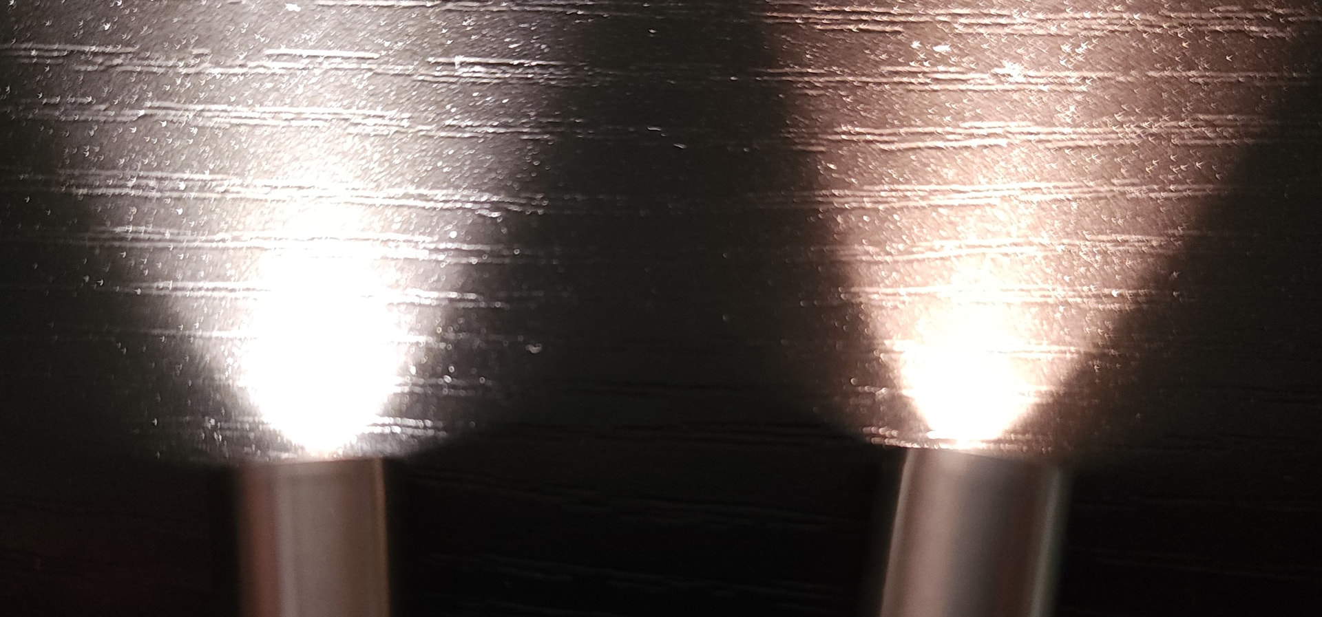
And a deeper reflector, with the same diameter, results in a smaller core of the spotlight, while the mid-brightness transition zone around the spotlight becomes larger, or brighter. A clear illustration of this effect can be found at the end of this article by get-lit in the CPF.
Unfortunately, that’s all for this section.
Calculating the actual beam profile for a reflector is quite complex. And even though the maximum lux is relatively easy to calculate, and impressive figures are often involved, the beam profile is not a trivial matter; on the contrary, in practice, it is frequently a decisive factor for the usability of a luminaire.
A slightly less bright but wider spot can be much more useful, even with a pronounced thrower. Sometimes it’s even essential to have noticeable light far from the spot. This way, you always have an overview at a glance, instead of having to swivel the beam. On the other hand, with very strong throwers, side-emitting light can hit you at close range and blind you. It really depends on the specific situation.
But if you’re wondering what lux level is actually achievable, if experimental throw is simply in your blood, then you just can’t avoid the things from Part 1. sigh [image]
Part 3 - And what if you want to do the math?
I’ll write the formulas out in a descriptive way, even if it’s not very elegant. sqrt() stands for “square root of”
Candela = apparently illuminated reflector area [mm²] * luminance of the source [cd/mm²] * losses.
Circular area: (diameter / 2)² * pi .
Luminances: some are given here.
Losses: reflector 15%: 0.85, lens 10%: 0.9, front glass 8%: 0.92 or coated 4%: 0.96.
Examples with Ø70mm, luminance 50 cd/mm², reflector center bore Ø10mm, normal front glass
- lens: (70/2)² * 3.1416 * 50 * 0.9 = 173 kcd
- reflector: (70/2 - 10/2)² * 3.1416 * 50 * 0.85 * 0.92 = 111 kcd
ANSI range (0.25 lux) = 2 * sqrt (candela), because lux = candela / distance².
You can start and stop discussing this topic anywhere. Let’s just get started. I’m looking forward to your ideas and opinions. There will be many more interesting points that also belong here.