Fenix E35 V3.0

Recently, I got asked by a colleague from work to try and fix his ( almost brand new ) Fenix E35. He bought it on his trip to Germany, used it very little, mostly as a “drawer ornament”… after a while, he tried using it for some car work and it did not light up. Battery was charged and tested.

He gave it to me to tinker a bit and try to make it work. If it works, I can keep it.

EDIT: Yup, brand new, used only a few times, he lost the receipt when packing up for the return trip, and can not call up on warranty…

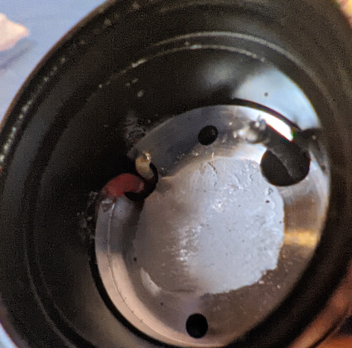
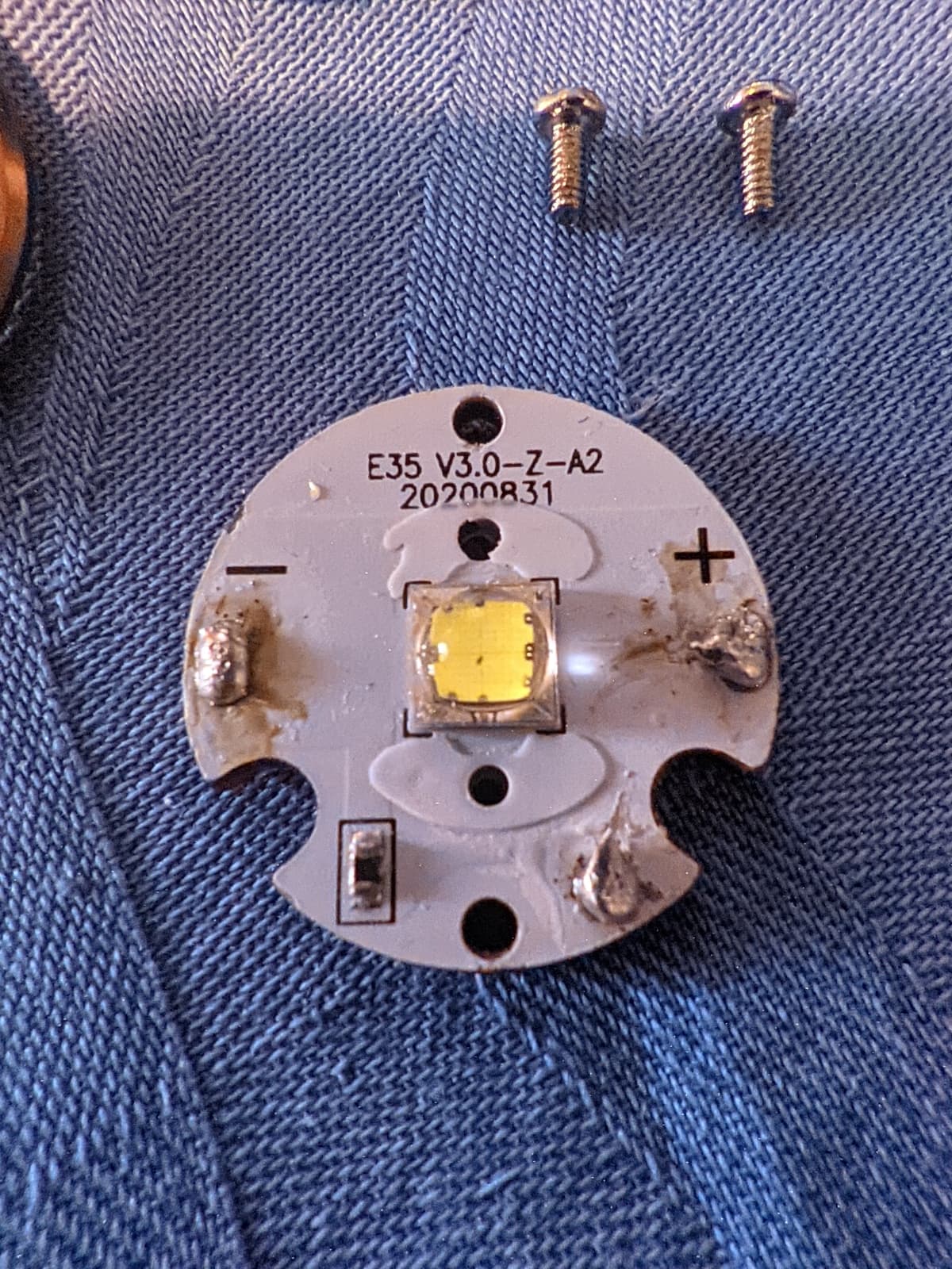
After carefully opening it from the front by removing the bronze ring, glass, rubber glass o-ring, diffuser and a conical white plastic stencil, emitter could be seen, an SST70 on a copper plate, cathode, anode, and what puzzles me… a 3rd white wire connected over a ( around ) 9.4 ohm resistor to the anode

After desoldering the wires and playing with a multimeter a bit, I found out that everything has a good connection, and the resistor is good. Testing with a diode mode on the multimeter, emitter gives no signs of life. I guess that’s 6V for ya’. Also tried directly connecting the emitter to a somewhat discharged 18650, no light whatsoever.

After that, I used the multimeter to test out if there was any power going to the emitter itself.

Fully charged battery, multimeter clips connected to plus and minus in the flashlight head, button press, green light in the switch turns on, aaaaand… nothing. No voltage on plus/minus. Tried that white wire and minus. I get around 2.4V to 2.8V, if I remember correctly. I guess that must be the Eco mode or something…

Any of you fine people have ideas as to what would be the best course of action?

A shot from inside the flashlight head:

And a closeup of the emitter:

If someone is able to answer, questions I have are:

  1. what is that third wire that connects to the the resistor, besides positive and negative one. Extra wire is also connected to anode of the emitter, but through a resistor. Why the resistor and an extra connection, what’s it’s purpose?

  2. Any way to pry out the driver? Anyone has experience pulling those out from Fenix flashlights?

Dropping in a 6V 20mm emitter set would be something I am willing to do, but I have no clue how to test if the driver and button is ok without pulling it out. And that’s the problem.

Thanks in advance, everyone.

Sir, unfortunately, I can’t give you any advice, I have a question myself.

I can’t find an information: is this lens covered by glass? Or is this lens open?
You have 2 tempered glasses in the photo. This is from a flashlight, tell me, this is a fundamental question for me!

As for the resistor on the MCPCB, I believe this is thermal control, which Fenix implemented directly on the MCPCB. For this, an additional wire is needed in this flashlight driver.


Reason for edit: I forgot that LED substrate is called MCPCB :smile:

1 Thank

Emitter is unlikely to die on its own. The driver might be toast. In that case, a new emitter wouldn’t fix it. It’s not straightforward to test a 6v emitter and don’t ever try to connect a 6v battery directly to it otherwise it can easily burn out in a flash. If you do have 6v power source, use a series resistor to limit the current. Something like a 10 ohm is a safe bet.

Also if the driver is dead, there is not much you can do. The host and driver are proprietary so other drivers won’t fit. You can salvage the battery, emitter / MCBCP and the optic at most.

The white wire seems to connect to the temperature sensor on the MCPCB so could be a temperature feedback for the driver.

I guess it’s just one of those infant mortality things for electronics. When you get it, stress test it to make sure it works.

It’s a pleasure to know you, suburbia!

Thank you very much! I sincerely wish you all the best in life!

1 Thank