Fenix RC40 teardown and mod

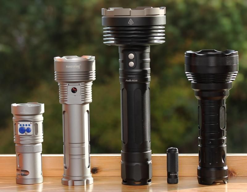
Size comparison with 3 other 6x18650 lights.

From left. Warrior (basically SRK size), Fandyfire SL3 (currently a project light), RC40, Fenix E15 (16340), "Retard light".

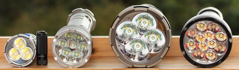
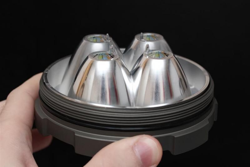
Lets take a closer look.

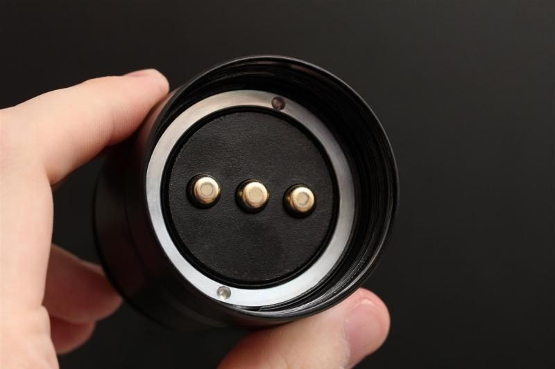
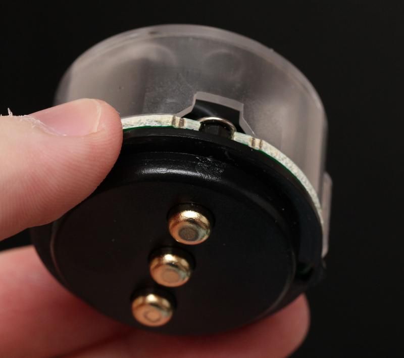
Battery pack is similar on both sides. Positive in the middle.

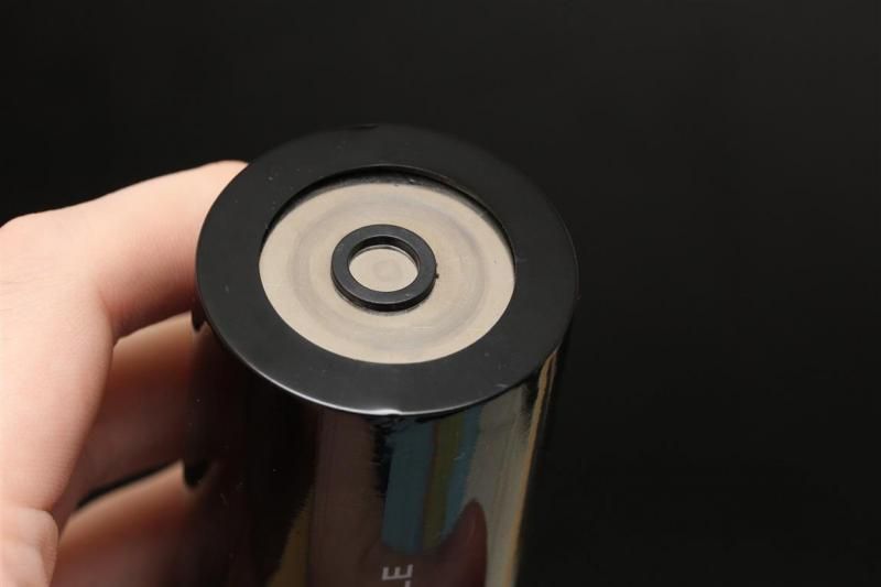
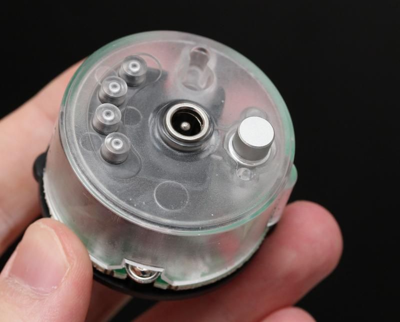
Here are the four battery indicator lights, button for activating them, and charging port.

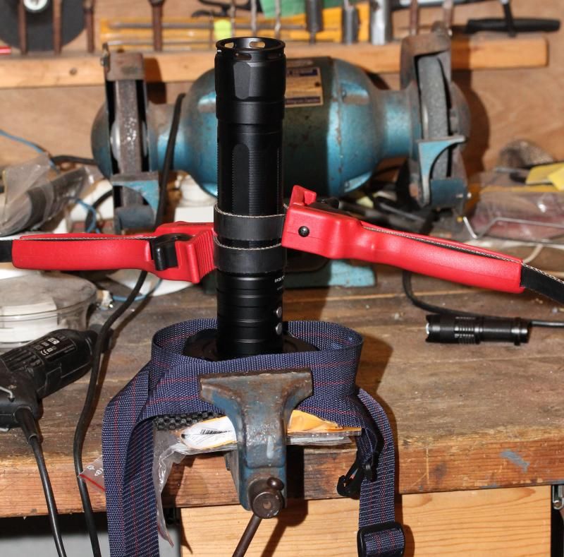
Bezel can be unscrewed with strap wrenches by hand. A good amount of force is required.

Considering the battery voltage and the 2s2p emitter configuration, this light could probably be rebuilt with a zener modded FET driver without too much work. I believe charging and battery monitoring would still work. (Unless the protection on the battery pack would cause issues, I have not measured that. Either way, probably something that can be overcome if its an issue.)

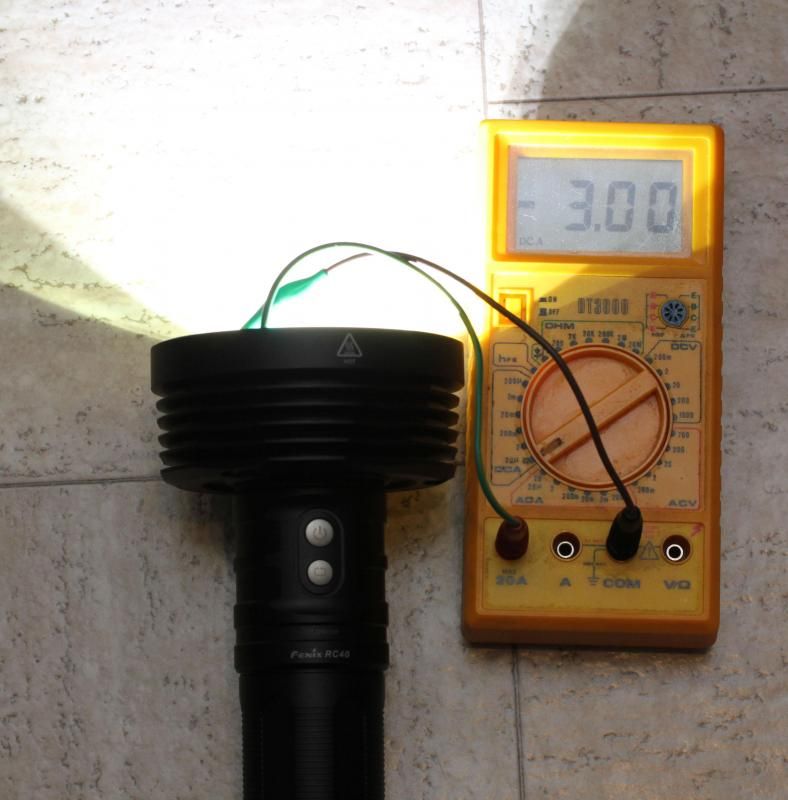
The light is well regulated though, so a linear driver may not be an attractive replacement. 3A at the emitter even with quite low battery voltage. Typical for large Fenix lights. Well regulated, well driven, but not overdriven. With latest gen XM-L2 this should be good for more than 4000 lumen OTF with the stock driver. And that will go pretty much all day on full output. Until the battery is empty that is.. Which does not happen suddenly due to dimming output at the end.

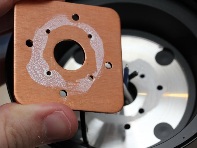
Disappointing amount of thermal grease, but it did not matter. A 30 min max output indoor tailstand test without cooling only showed about 250 lumen drop. Which is natural heat sag when the hottest part of the light goes from around 23 C and to close/around 60C. Aluminium below emitters are not thick, but certainly adequate. The light is built like a lightweight where it can be (plastic high quality reflector, no excessive amount of aluminium in the middle of the "pill/head"). But in general its built like tank with massive heatsink fins, oversized wires, massive well secured copper mcpcb, etc...

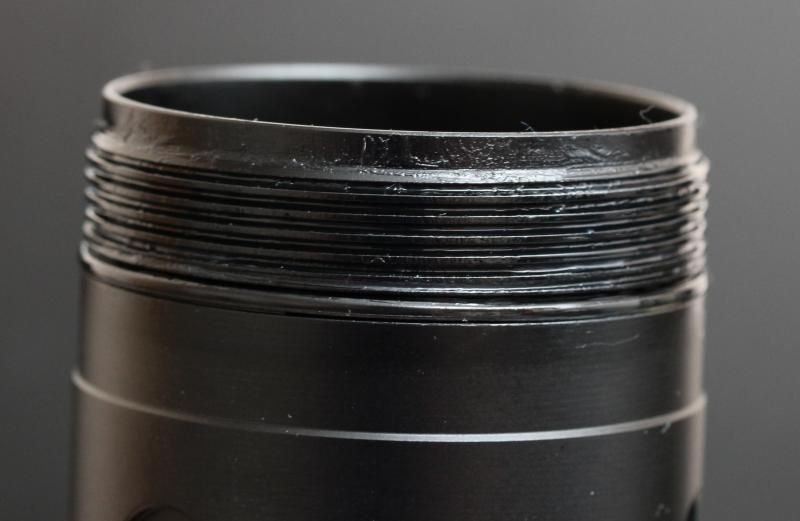
Fenix does not what you to open this light! I had to attach the light in a vise and use both my hands in combination with two strap wrenches. Pushing from me with one hand, and towards me with the other. Using all my force!

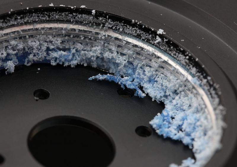
Blue loctite or whatever they used must have been free the day the light was assembled. :D

That is a new record for me.. Before you think; "That is not bad, all those threads were not even properly covered with the stuff."
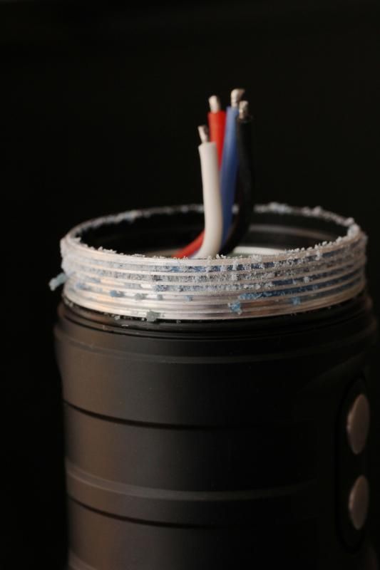
Yeah they were!

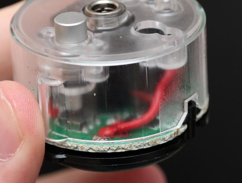
Since the sense resistors were on the top side of the driver, I never opened it up further.

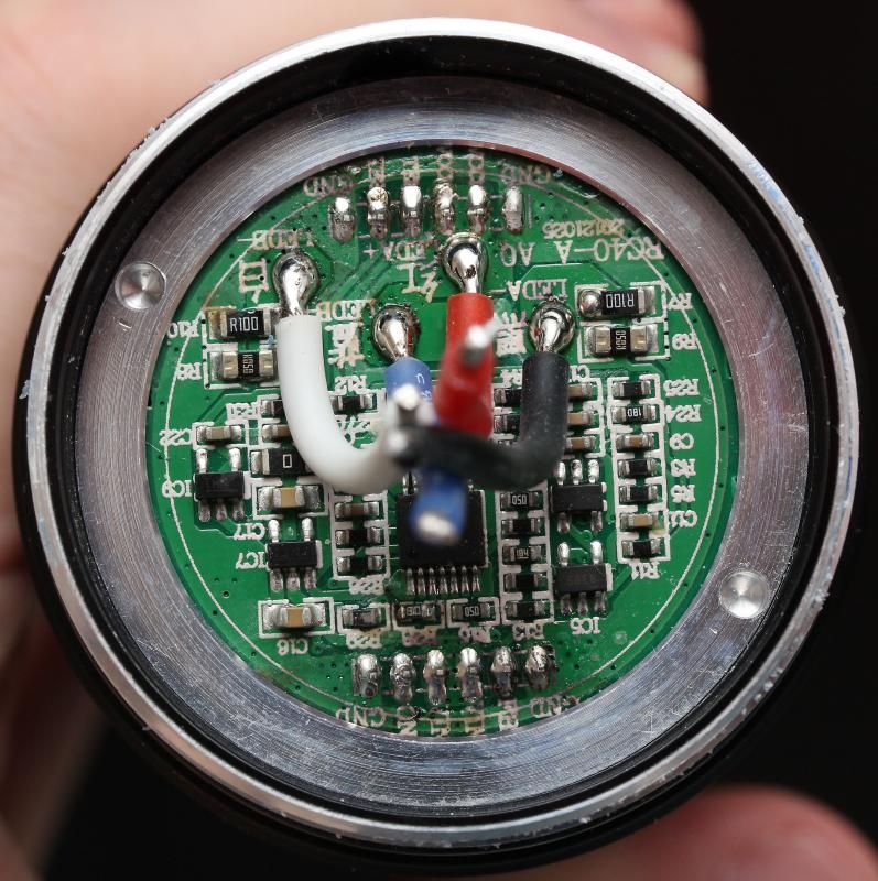
One of my first test setups with resistors.
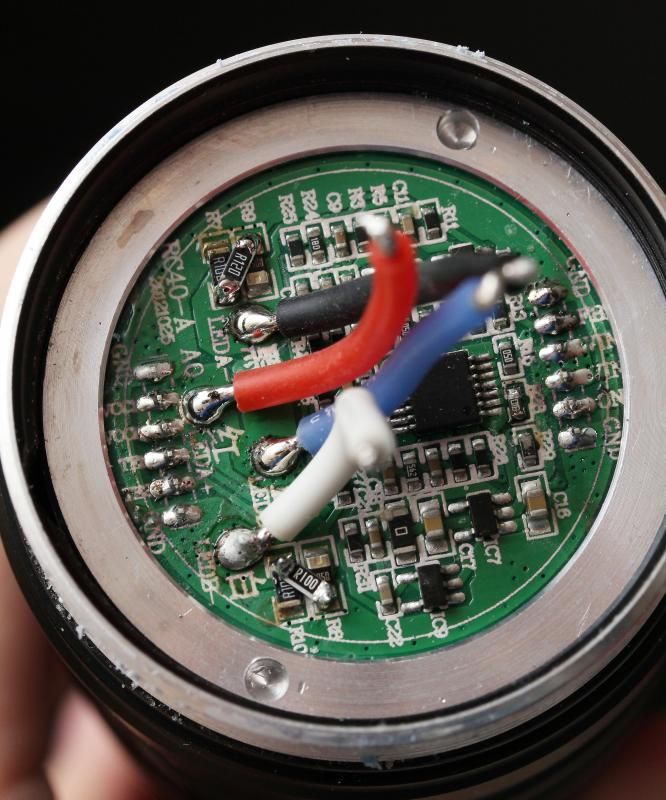
Mod notes:

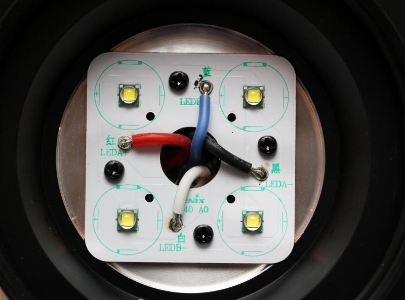
This is my personal notes, so they may not always be super easy to follow. There are different groups of resistors on the light, and two sets of output wires. A and B. In some cases I only measured on one side.

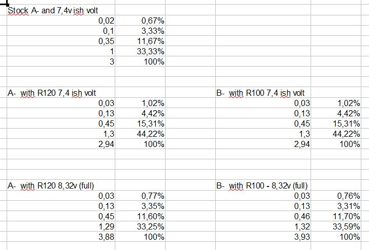
The notes below show emitter amps and mode spacing on the stock light with low battery voltage. Then you can see it with two different resistor mods. Which gave lower output due to low battery. Then I charged the battery, and saw around 3,9A to each emitter depending on the resistor value that was added.

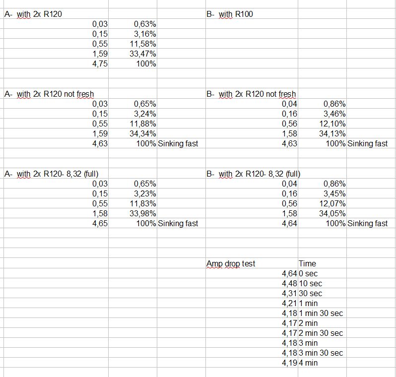
I was able to peak at 4,75A to two of the emitters.

When attempting to get 4,75A to all four emitters output was lower. A timed amp drop test showed it was sinking like a rock down to about 4,2A. Based on that I considered 4,2A to be the absolute max.

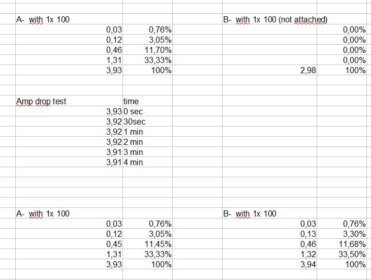
I decided on using a single R100 despite that it only had showed 3,93/3,94A.

Reasons being, I did not have an R090 or R080, I did not want to bother swapping all resistors in order to give me a combo that gave me above 4A with the resistors I had available. I wanted to be on the safe side, and if XM-L2s are more demanding I might have some headroom with going for 3,9A instead of 4A+.

A single amp drop test showed good regulation.

I then decided on just adding a single R100 on both sides.

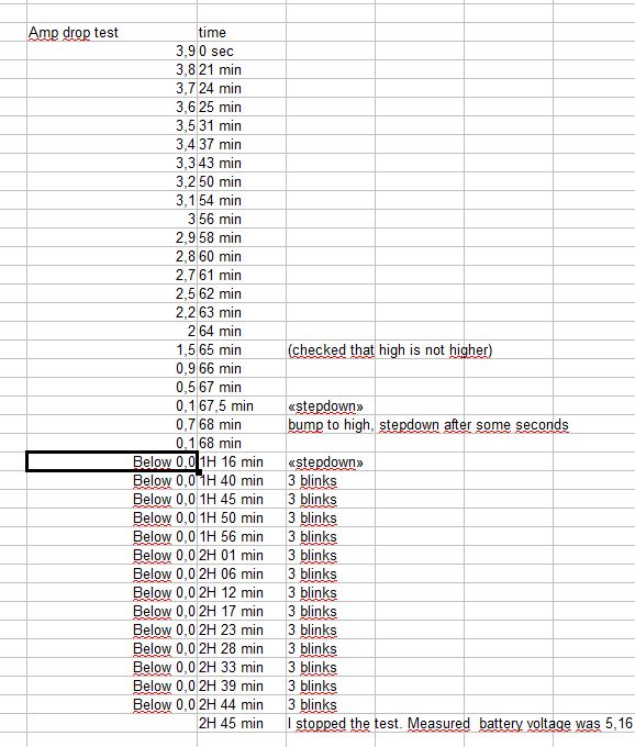
Time for a proper amp drop test from full battery to empty. Summary:

I got 0-20 min with proper regulation and the full output of the resistor mod.

From 20-56 min output was dropping down towards the stock 3A.

From 56-67 min output is falling quickly.

From 67,5 min it does a stepdown down to around 0,1A.

Ten minutes later it did another stepdown that was even lower (below 0,1A, not below 0,0 as my notes say:D ) It then did 3 warning blinks every 5+ minutes.

I suspect that you are not supposed to use the light more then, but you get the ability in case of an emergency.

I continued this test for a long time. About 1 and a half hours of this super low output mode I decided to check battery voltage after a total runtime of 2 hours and 45 minutes on Turbo/max output setting. Battery pack showed 5,16V (or about 2,58V on each cell). Probably beyond what is healthy for the 2600mAh cells in the battery pack, so i stopped the test there and charged the battery.

On some other Fenix lights (TK61 and TK75) I have tested there have not been a cut-off based on testing with a powersupply, so I always recommend protected cells in those. Im not sure if the RC40 battery pack have protection for low voltage, it did not seem like it, and I did not want to discharge it any further..

Light output numbers:

Measured by me. I don't claim accuracy.

Stock:

3591 Lumen, 134kcd

Resistor modded and stock emitters:

4326 Lumen, 162kcd

I have basically increased current by 30% (from 3A to 3,9A). Both lumen and lux have increased with about 20,5% from stock.

Resistor modded and with 4x XM-L2 U3 1A:

Coming later?? Theory says 22% increase IF i get similar emitter current. So I could get up towards 5277 lumen and 197kcd?

Resistor modded and with XM-L2 U3 1A, 2 de-domed:

Coming later??.. maybe.. Could give me up towards 5013 lumen and 285kcd. Maybe...


Disclaimer: This light does not want to open up easily. Mod at own risk. Have fun!

Thanks for taking a chance with your expensive light. I know of the extreme hassle that can come along with opening up some glued lights and the risks associated with ruining a prized example. Have you had a chance to consider a battery carrier mod of some sort to ditch those 2600 mah cells and make them easily replaceable in the field? That would make this one sweet mod light. Perhaps a gutted and rewire of an X60 carrier with spring reconfig? At least it has the proper framework and maybe a mish-mash of the two could be made into something workable. Let me know if you need any measurements.

I hope youre L2 upgrade goes as expected. Although completely different, I remember reading of a TK70 mod that didnt fair well with the L2 mod, and Ive conjectured that it was for the higher vF that didnt play well with the driver.

Fenix does not want you to open this light……

annoying.

Nice light, I'm not sure I would want to mod such a well driven light though, but I guess the old gen XM-L's keep staring at you until you start doing it.

Time will tell how the XM-L2 upgrade goes. Could take several weeks before I get them..

I have thought about an upgrade to the battery pack. Rebuilding the battery pack have been my main thought, but not sure if its worth to bother with it. Im not sure if I can get 3400mAh cells to fit anyway. They are quite long, and the stock 2600mAh cells may be short so that could become an issue.

I know K40M battery carrier easily fits.

What is the size of X60 carrier (length/width)?

Lots of premium light manufacturers does not want you to open their lights. Luckily its mostly just a matter of technique and tools to get them open.

No scratches on my RC40 from the vise. Luckily the head isn't 100% round everywhere on the heatsinking fins, otherwise it would have been a PITA to open it up.

The main issue for me with several of the Fenix, Acebeam and premium lights I have modified are that they are often nice and regulated when stock, but that is not always the case after the mod.

Its strange that Fenix have not made an update version of this light yet.. It begs for an upgrade, hopefully my attempt will turn out well.

Wow. That's a lot of thread locker and a lot of threads. You had to have really torqued on that tube. Congrats on having the strength and not damaging the head. Its a good thing you didn't need heat. Blue requires around 500F to liquify.

Thank you for the break down shots. It appears that much of that emitter MCPCB was making contact with the shelf. I'm betting much more will be after you're done with this baby.

Best wishes and looking forward to what else you have to say about this light and what you do with it.

Nice effort getting that apart. Your a better braver guy than I. I cant tell you what the light would of looked like if I'd tried that.

Thanks Ima4wheelr.

MRsDNF, we both know your light would looking stunning after you worked your magic. The light would have great knurling and people would drool all over themself when looking at the light.

looking forward to hearing your mod results

Race, my X60 isnt with me ATM, but I’ll post some measurements of the carrier as soon as I can (hopefully tomorrow).

While you have the reflector out, can you please try a simple test for us? Tail stand the light in high mode for about 5 minutes and let it begin to heat up. Then compare the emitter mcpcb temp with the outside head temp (the finger test would be good enough). Im hoping that both will be close to the same temp.

I put the light together yesterday evening/night for some outdoor use. I unscrewed the bezel again and did the temperature measurements you requested on my resistor modded RC40 today

MCPCB temperature is measured on top of the copper mcpcb between two of the emitters.

I measured the "hottest cooling fin" on the underside of the bottom cooling fin when the light is tailstanding.

I used a cheapo IR meter. Dont expect perfect accuracy, or that my readings were 100% consistent.

Cool light/before 5 min run:

Hottest cooling fin: 24,7C

MCPCB temperature: 24,7C

Around 5 seconds after a 5 minute run:

Hottest cooling fin: 50,1C

MCPCB temperature: 50,4C

Around 1min 15 seconds after the 5 minute run:

Hottest cooling fin: 47,1C

MCPCB temperature: 47,7 C

As mentioned in OP. When the light was stock I did a 30min indoor runtime test when it was tailstanding without any cooling. Output drop was less than 300 lumen (about 250). That represents about a 7-8% drop from stock. Which is more than most would get outdoors under normal use when using the light 30 min straight on max output. Im taking a guess that the stock light here in the North would have around 3-5% drop at worst with lots of continuous use on max based on a standard temp of 25C. A resistor modified light will probably see around 4-6% drop at worst. In my case that means 30% increase in current. 20% increase in output, and 0-1% increase in heat sag depending on use and weather.

If you check specs from Cree you will see that if an emitters goes from 25C to 60C you will get a 7% drop (same as my measured drop on the 30 min indoor test). So that is just what I consider "natural" heat sag.

Based on what I can see the light have excellent thermal transfer and can easily handle a little current boost from a temperature perspective.

Ill try and update OP a little later with lots of resistor mod notes.

-Added 2 exterior shots

-Added resistor mod notes and "amp drop runtime tests"

-Added some numbers

Feel free to comment... :)

Congratulations on your mod results. Thank you for the temp measurements and thermal performance confirmation. Im sure you’re thinking about how to better power it now.

The X60 carrier is approximately 41mm x 163mm and has 3 screws in each end that hold it together. Depending on what you find inside the RC40 pack, this might help lend some parts for your purposes. If its too long, I dont think it would be difficult to shorten. Having said that, you could probably make your own and salvage the balance circuit and end caps from the RC40 pack. An easier route might be to find a pair of 3 x 18650 carriers to mod. These are certainty cheap enough and appear to be well made, although serial and would need to be reworked. Again, darn Fenix for not offering a cell carrier for this light!

Before you break open the pack, maybe you could charge it completely first. Then after opening, you could measure each cell voltage to see how well the balance circuit performs. If it does a good job with equal resting voltages, then its probably worth saving. If not, ditch it and know that you exposed a weakness while shortening cell life that might have proven to be dangerous.

Of course CNQG went down again in trypical fashion. The link was for the improved DRY carriers @ $5.70 each.

http://webcache.googleusercontent.com/search?q=cache:HQEthakAHD8J:www.cnqualitygoods.com/goods.php%3Fid%3D1459+&cd=1&hl=en&ct=clnk&gl=us&client=firefox-a

Sweet mod. But the light? I cannot for the life of me find it "nice". I like the retardo light better than this.

That said I don't think it could never change if I had it in hand and used it a lot.

Anyways... Anough about me. The mods are sweet. And it's nice to see that there are options out there for those who really want that good regulation. Thank you for the review and the pictures. It was a joy to read it :-)

@Flashpilot.

Im quite happy with the power now. (Although, I would not mind that it was even higher 0:) ..If it was regulated...)

RC40 pack: 43,4mmx 145mm, so I don't think the X60 carrier or a custom pack with springs and RC40 circuit electronics could become that short.

Maybe its possible to make the battery compartment longer, but I never looked behind the driver where the switches are.

Buying an RC40 is like buying a Porsche, if you want to buy some extras (like battery), you need to pay... Not budget friendly.. But having several battery packs would be sweet. Quick changes rock. There are pros and cons to every battery setup. When that is said, personally id take a battery carrier.

If I decide to open up the pack ill report back. Gonna enjoy the light a bit now.. Only owned it for 3 days, but so far 95% of the use have been test related.. And I have lots of other projects that are higher priority...


@Ledsmoke

Thanks for the feedback. Glad you enjoyed reading. (btw, I have now fixed some typing errors in OP, but im sure there are many more)

I see nothing bad looking with the light. Its big and bad ass! :D Well balanced. Despite its massive size, its only 100g heavier than the loaded retard light.

The side of me that says there are still a couple companies in this world that charge a premium to provide the best compromise between power and safety says there is a balancing circuit in that battery pack. The jaded side that says greed usually rules, says there isn't one in there.

I prefer to believe that there is a balancing circuit in there, but I would not blindly trust that side Especially after seeing that chincy amount of thermal compound. I know the compound is an assembly line issue, but it would nag at me to no end and I would not be able to just assume that a just as chincy a design decision had not been been made.

EDIT: Sounds like the battery may have some good built in protective circuitry. Sears sells a replacement battery and it had this text in the description:

The battery has triple over-heat protect for safety and reliability - Built in over-charge, over-discharge protection circuit to ensure the maximum performance of the battery - The circuit board has front and back protections to make it more impact-resistant and reliable - No battery memory effect, negligible self discharge.

You beat me too it. I checked online and read the same regarding the battery pack.

I also checked the manual:

[quote]

Over discharge protection

When the battery voltage is extremely low the RC40 will turn off automatically to protect the Li-ion battery from being permanently damaged.

[/quote]

I guess the protection is at 5V then. I "only" discharged to 5,16v.

About the amount of thermal compound: it is nice to have the right amount, but it is better to have too little than too much, the board is screwed down on the aluminium plate with 4 screws and that alone accounts for so much metal-metal contact surface that the job is done already, adding so much thermal compound that it decreases the amount of direct metal contact would fast make things worse. A little bit of paste like this looks very ok to me.

I may have missed it but how was your final R100 resistor positioned on the driver board? I did not see where the final was clearly stated and the modded board photo seems to show both an R100 between R8 and R10 as well as a R120 between R7 and R9.