Can you do a driver for haikelite mt03 II?
I did in the past mod normal SRK drivers for MT03
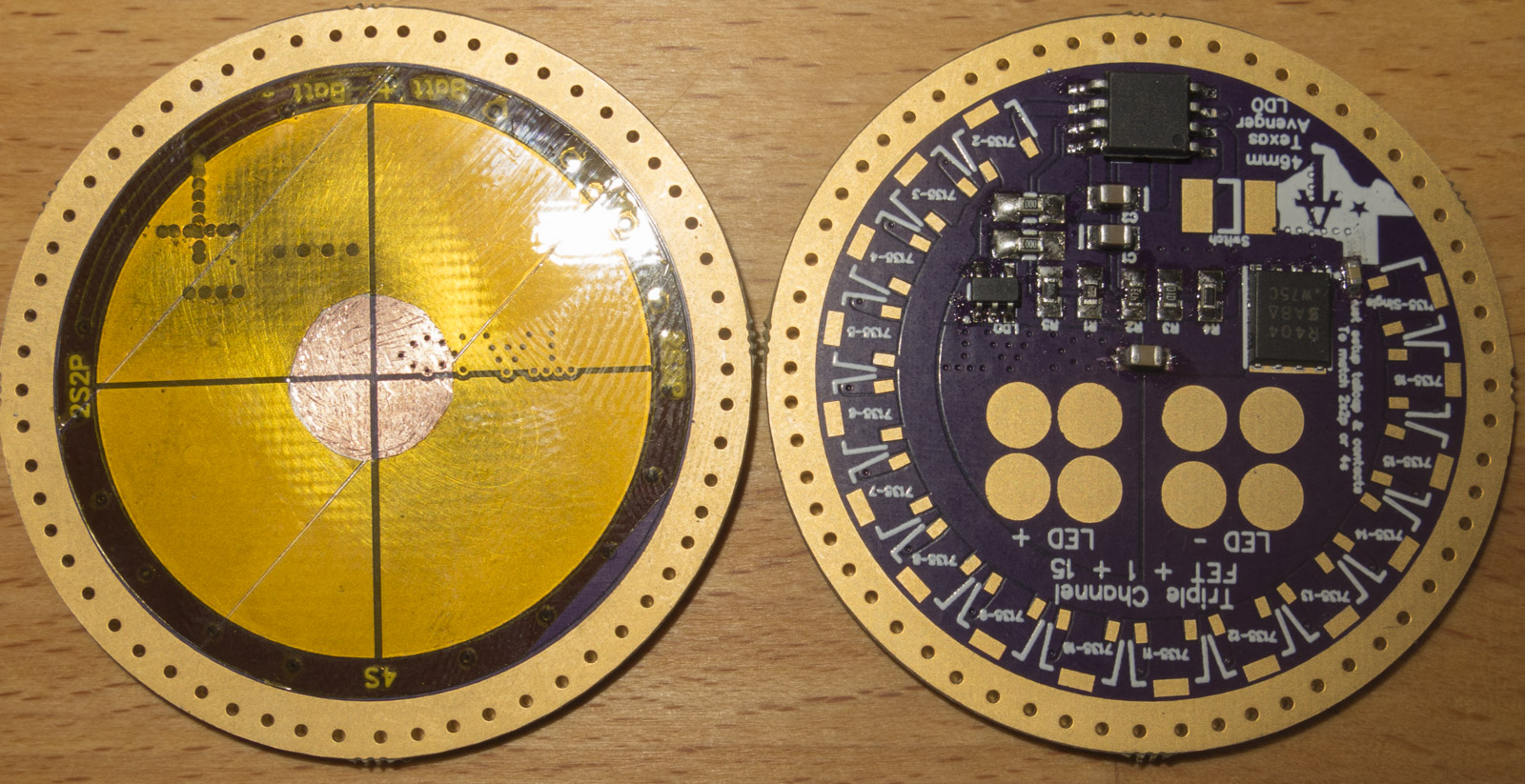
as I have only one SRK driver board left I did a dedicated MT03 Design on Oshpark
list updated with more details

The e-switch bistro-HD is working just great now. Just polishing up minor things on the release, like the flash scripts and re-testing on a clicky light again probably before release. There are already versions that will be included that will not only work on the rear clicky, but versions that can use both the switch and the clicky, with options to do different things with the clicky... either normal (noinit/OTC/OTSM) operation, or always comes back on in same mode, or always turns on in turbo. None of that's tested on a real dual switch light yet so may need to get the quirks out. Testers will be welcome.
Yes until then the usual build should work on the forward clicky anyway. I've never used bistro on a forward clicky. No reason it shouldn't work. Med press is slow enough that's it's possible to double click (as you need to with forward clicky) and still get a short click. It might help to relax the timing config and recompile. Simple though.
I had trouble getting used to Narsil when I took it out. I was worrying about traffic and people and power use, and I couldn't remember which way I was ramping or if the reversal had timed out yet, and as a lantern didn't know how high up it was cranked (how long it would last). Bistro is less slick, and the long-click off less comfortable. It doesn't have all the shortcuts either, but simple has advantages when the mind is occupied. But mostly I'm probably just used to it.
Ok, just tested on my light, and yeah, double clicking fast works reliably for short click. It's kind of why I've been thinking about making med press faster, but forward clickies are a good reason to maybe leave it alone.
I wish to thank Lexel for what he is doing with these drivers. I have bought several. The latest one was a “special” on a 17 mm board. No FET, just 7135*1+1 = 700mA. It is perfect for the application. Love the Narsil ramping. That was the whole point.
So Thank You again, Lexel. I will be getting an order for another couple of specials to you soon.
Got today 6 MF01 boards

Excellent! I just sent you the money for one of those bad boys right there! I can’t wait to get ramping on my MT-01. Thanks for deisgning, flowing and testing these. So good!!!
I received my two drivers and they are looking good. I just don’t know where to connect the 3 wires from the switch. On the the TA driver only one connection is pre-tinned for the switch. I have a red , ablack and another red one comming from the switch. I f someone could upload a pic from TA Q8 driver and draw which wire should be connected where that would be a great help.
Sounds like you have a lighted switch no? One of the reds would be for switch and one for LED if that's the case. Black should be ground. The switch connections are labelled either SW or OTC, just check out the Texas Avenger thread for pictures. For the indicator, if it's a 1S light, in principle pin 7 can be used, one of the divider resistor pads. I don't know if Narsil supports that yet on TA boards. I think I have a bistro-HD release that does. You should be able to tell which red is the switch by measuring resistance between it and black with the switch open and closed, and of course you can tell which pad is ground by either looking closely at the traces on the TA page, or testing resistance to ground.
Connectioms is in the OP
Sideswitch is always a SMD resistor soldered only on one end
I recommend securing it with glue after soldering
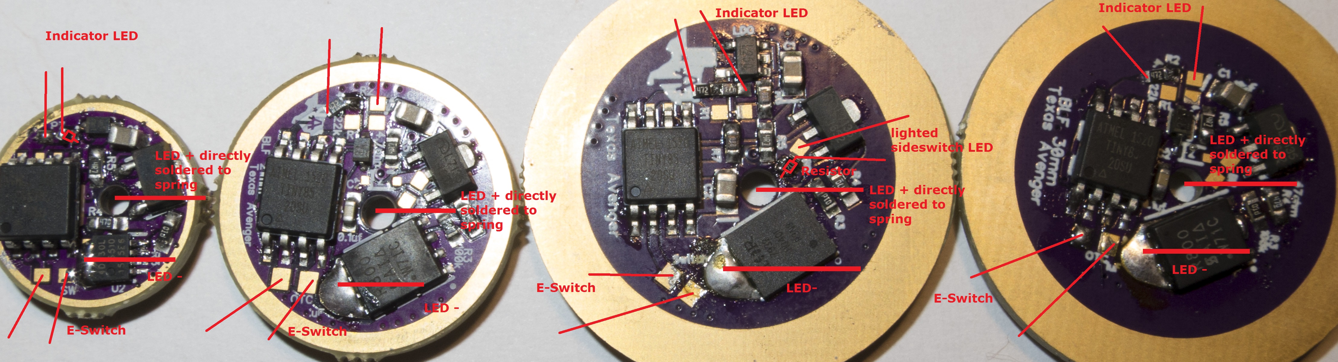
I have a picture of the smaller 30mm driver. Does it look like your Q8 driver?

Sorry for the late reply, I’m having internet problems….
The layout of the TA Q8 driver looks different from all the other drivers shown here, numbering of the pads is also different.
I wanne use the original indicator LED and resitor (which is soldered to the switchboard I believe).
So 2 of the switch wires (red and black) go to the switch pads on the the TA driver, then I think the third (red) wire goes to R6 (which says Indic.) it has 2square pads and on one square there is a circular pad connectted to. Is this correct? Do I solder the third wire to the pad with the circle or the other square pad?
I don’t wanne be messing with adding resitors and stuff as my reflow station is down, I just want to replace the driver and keep the rest of the light as is (switchboard and indic LED work proper)
I'm surprised the switch needs a resistor. Isn't the sense pin operated in input/tristate mode? I think you meant the LED right? That's what you show in the picture, a single-ended resistor for the LED, not switch. So I'm guessing that means most lights don't have the LED resistor already in the switch assembly?
TK's been playing with driving LED's from tristate with an the internal pullup resistor set. I think that's about 35kohms though, so a bit high/dim even without an external resistor.
I wish to order a 30mm and 2 * 17mm, Narsil. Details sending in PM
He meant switch led, not switch.
Since he’s installing it on a Q8 there should be a resistor on the switch pcb.
I think Lexel might need to post a picture of the Q8 driver and label the pads where the wires go.
Can you post a picture of the driver?
In Lexels Q8 pic I don’t even see an R6.
I assume the Q8 switch uses a common ground for both the switch and switch led. One of those 2 switch pads should be ground and one positive. Verify those.
I assume you already identified the 3 switch pcb wires. Pos to switch, pos to led and ground.
As for where to attach the switch led wire, did Lexel add a resistor for you? He may not have. This is where a picture can really help. Also, you might try adding power to the driver and see which of the 2 pads your looking at for indicator switch gets pos and which is ground.
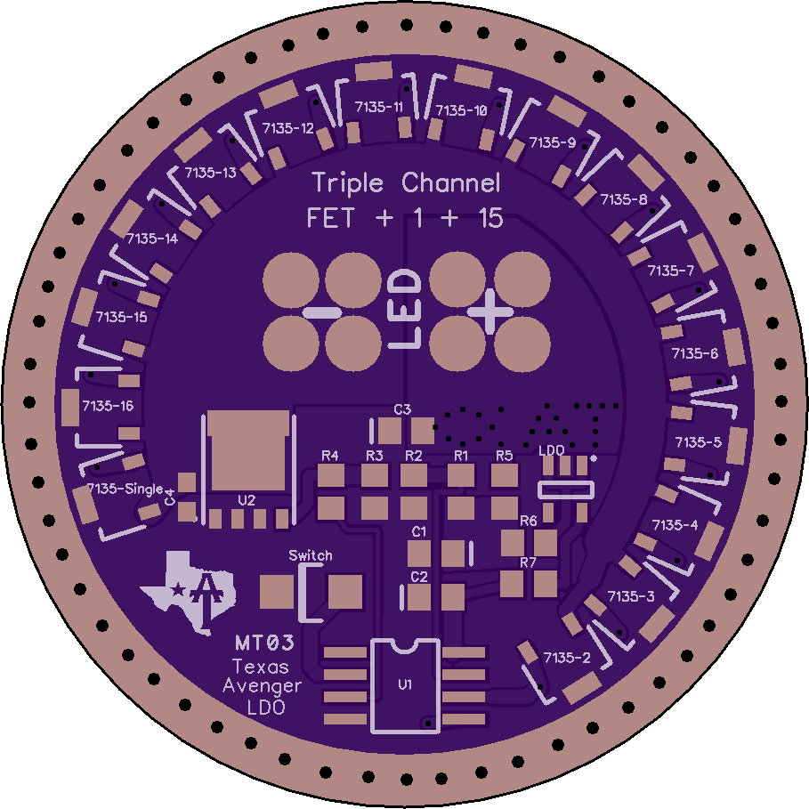
I just checked and the pic in the OP of the TA Q8driver has the same layout but has different numbering of the pads. the R6 pad on my driver is R1 on the pic in the OP.
There is no resistor soldered on my driver, it should not be needed because there is a resistor on the switch board.
This is how I think I should solder the wires. Can someone confirm this? (Right) Click the image to get it bigger (posted on IMGUR)

It is not visible in this pic but underneath the indic. LED resistor (Pad R1) there is a square pad with a round pad connected to it.
Can I get a 30mm board complete with NarsilM
Add R6 easy to solder LED resistor
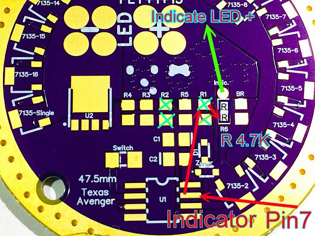
Sorry steel but you are confusing me man, the way you draw it up is completely different from the pic that Lexel posted. You would solder the resistor to the 2 square pads R6, while Lexel soldered one side of the resistor to the square pad with the circular pad…… I also don’t understand the arrows and crosses on your pic…
I want to keep using the switchboard with resistor on that board and NOT on the driver. Is that possible or not and if not why not?