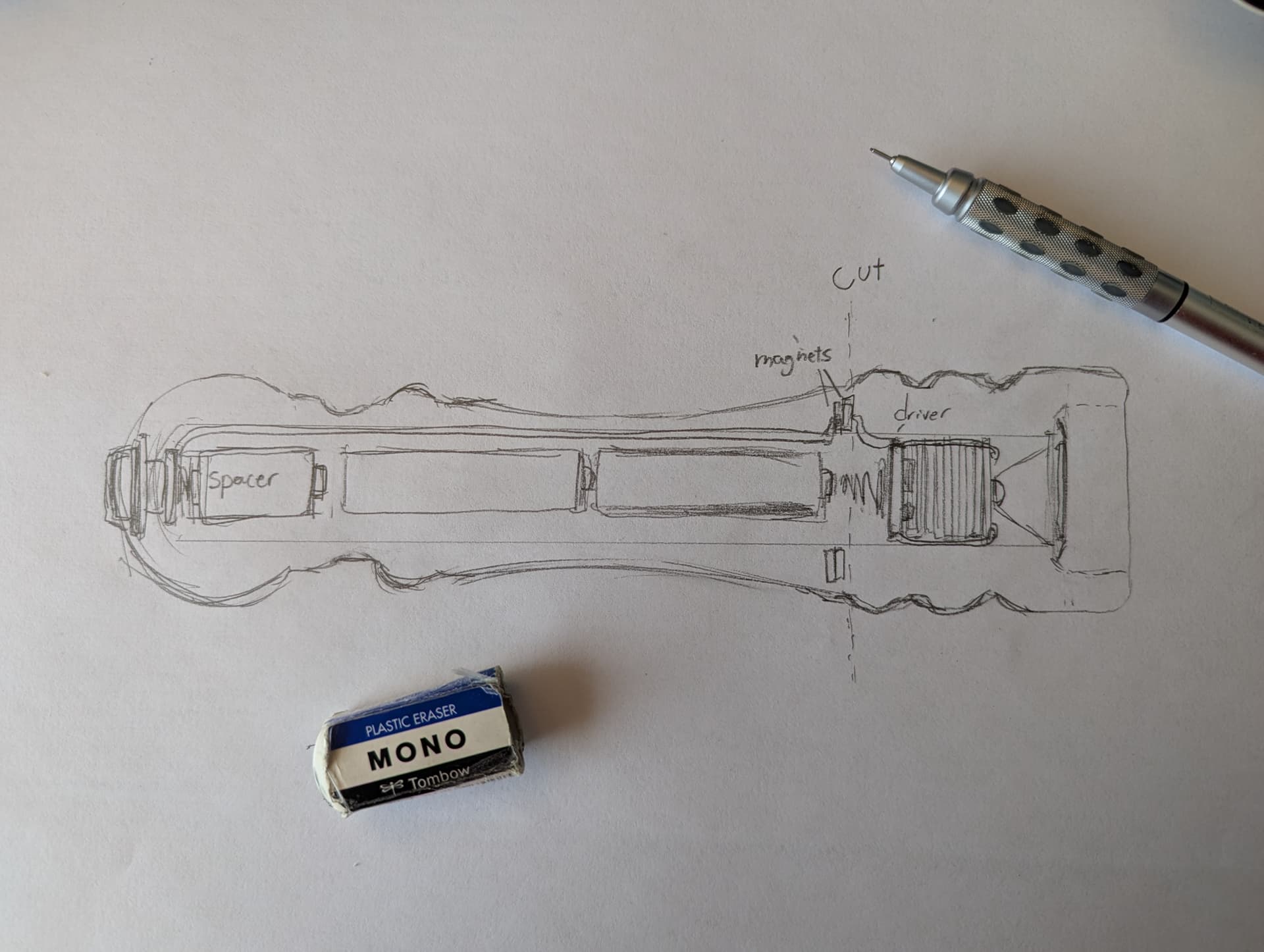
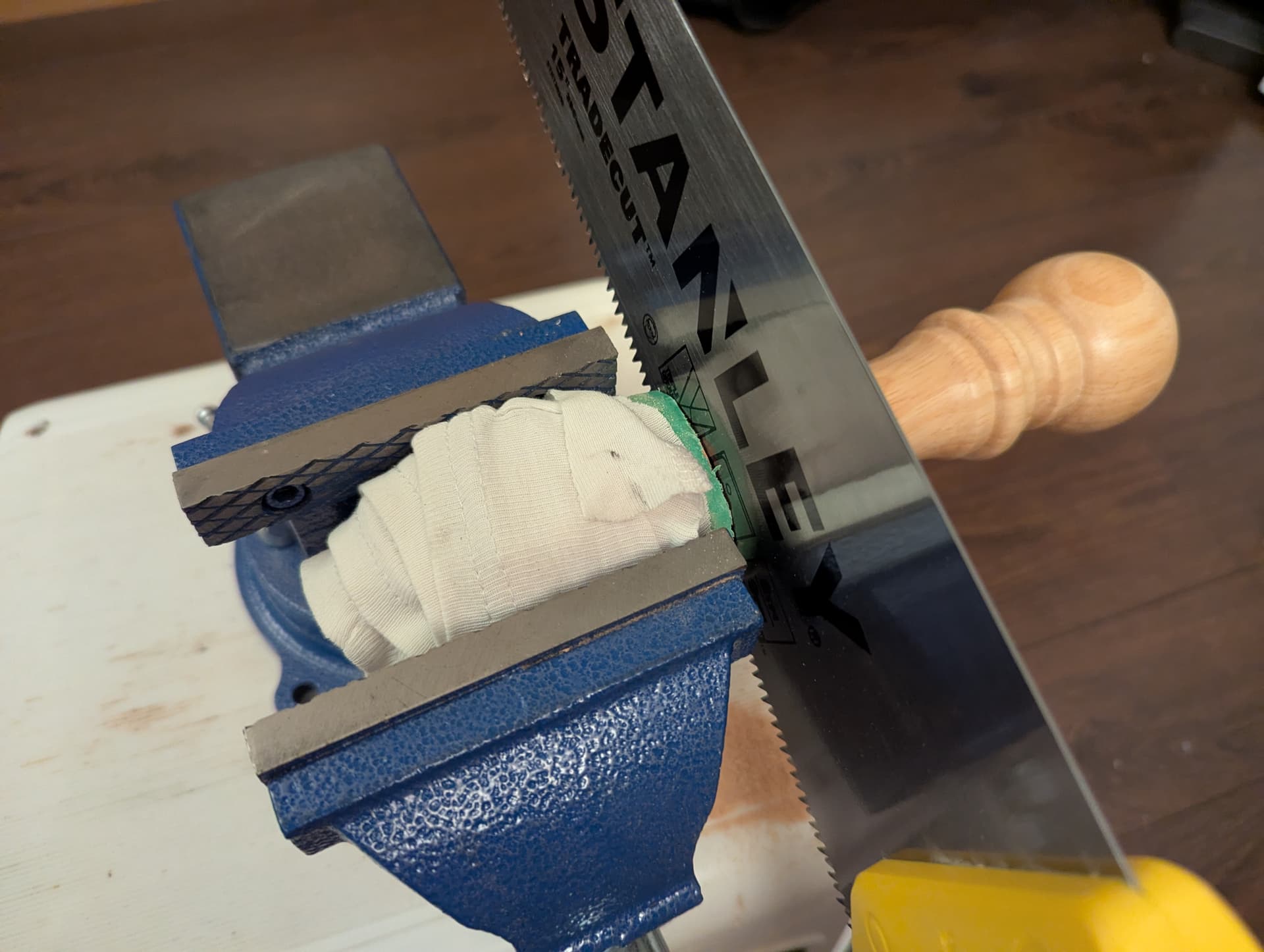
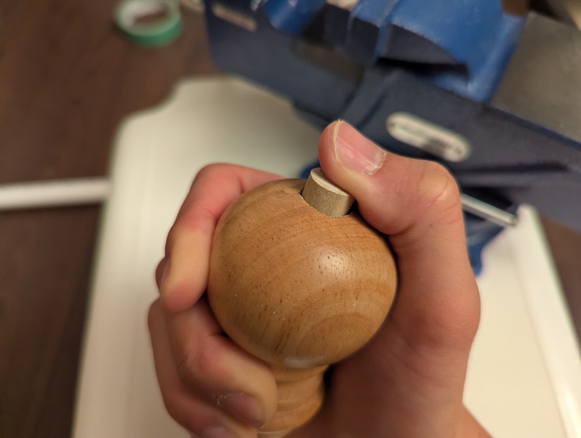
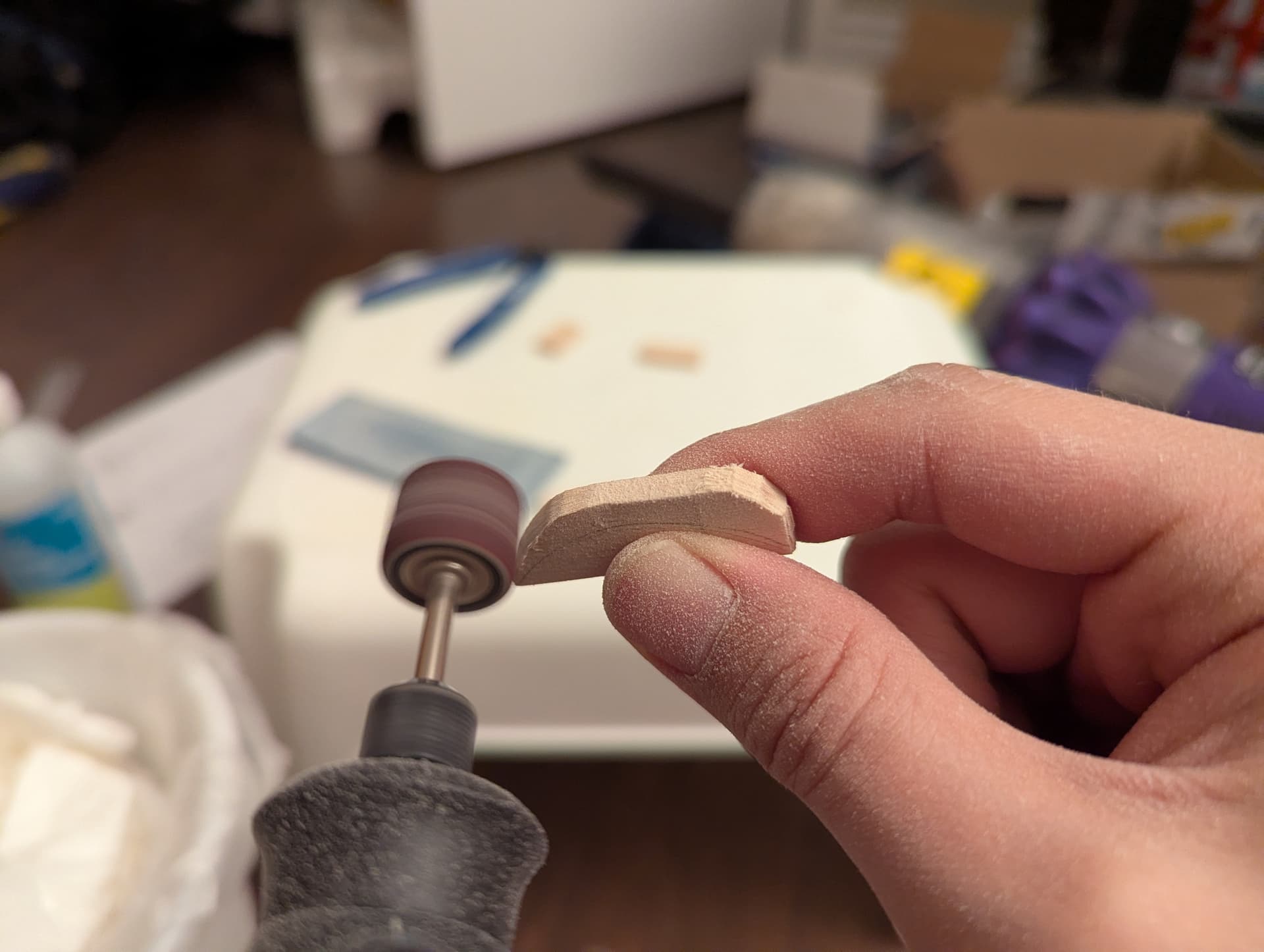
Time for my next challenge: connecting the head and the tail!
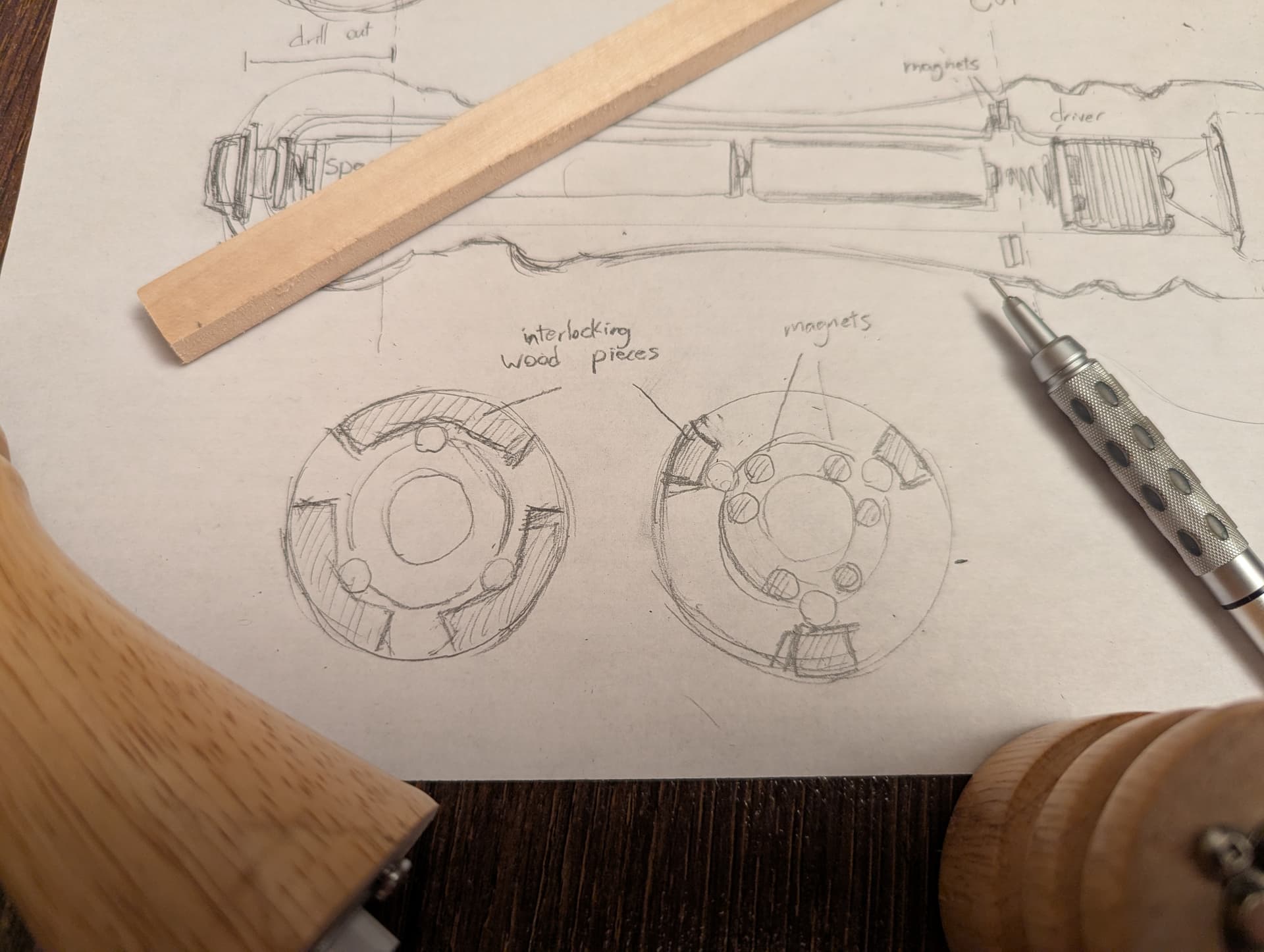
In my sketch, I proposed to do this with magnets. Magnets will be able to hold the ends together strongly, and if I’m smart about it, they’ll be able to complete the electrical circuit too!
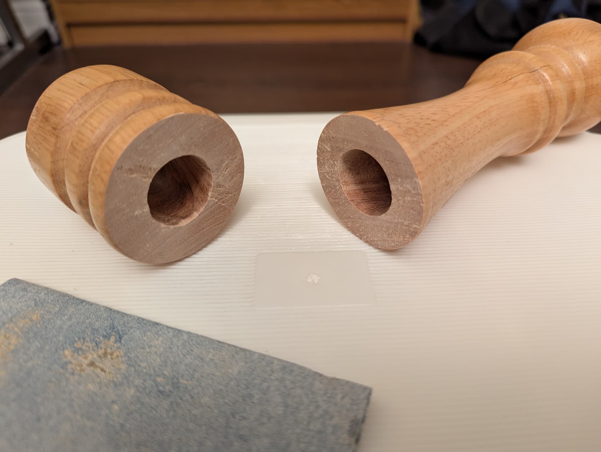
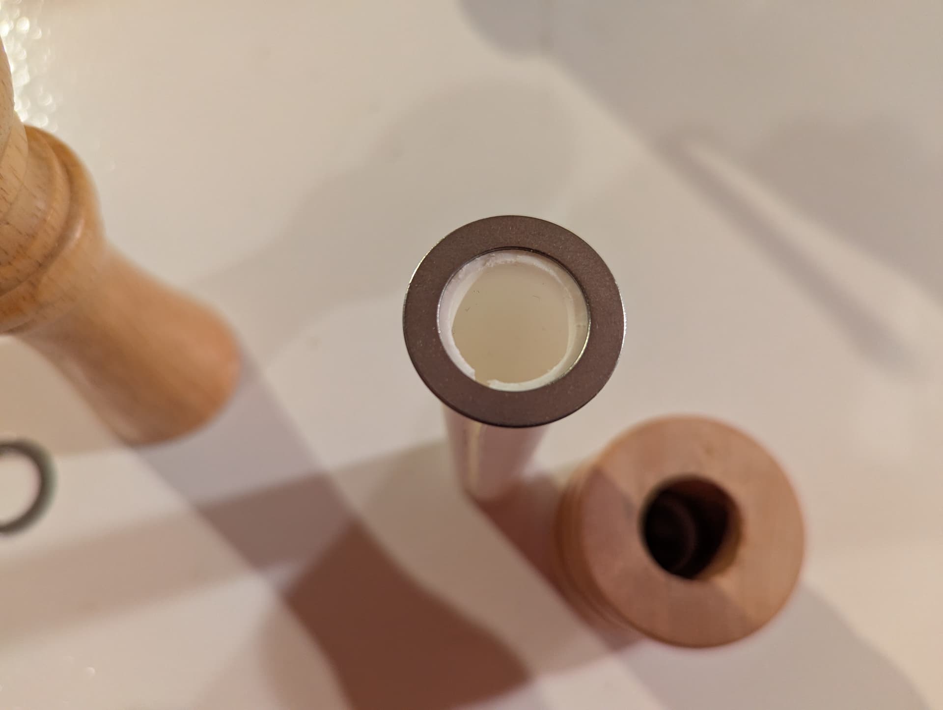
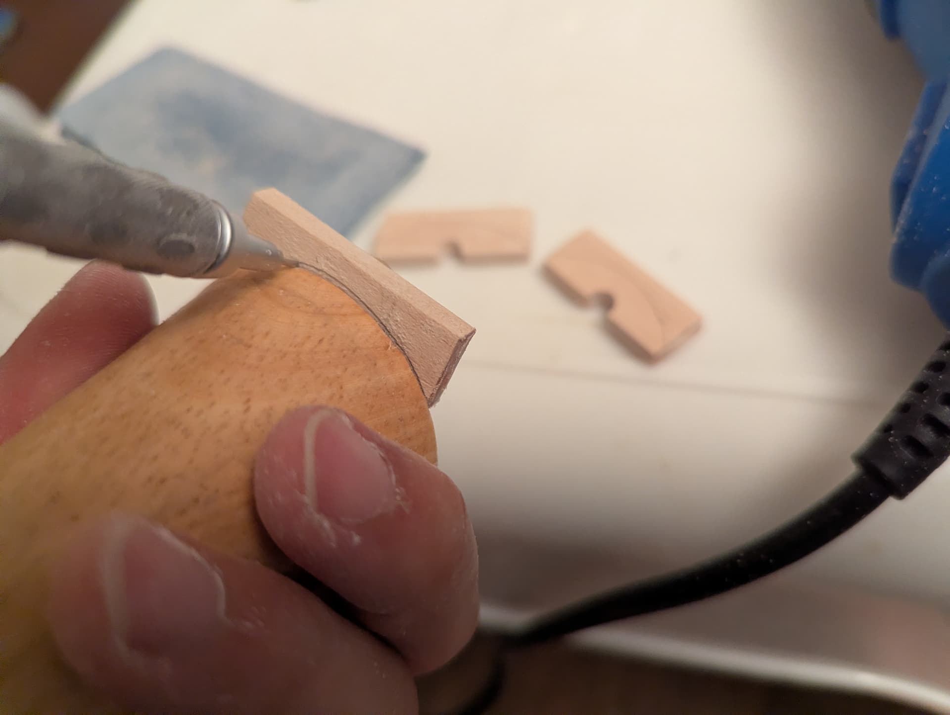
However, wood isn’t magnetic. Or conductive. So I could drill holes in each end, and glue magnets within. But then they would be dependent on glue alone to keep them in place, and it would also make it hard to connect the magnets to the circuit. After some pondering and wandering the hardware store, it struck me: washers!
They hit all the criteria:
- Ferromagnetic
- Conductive
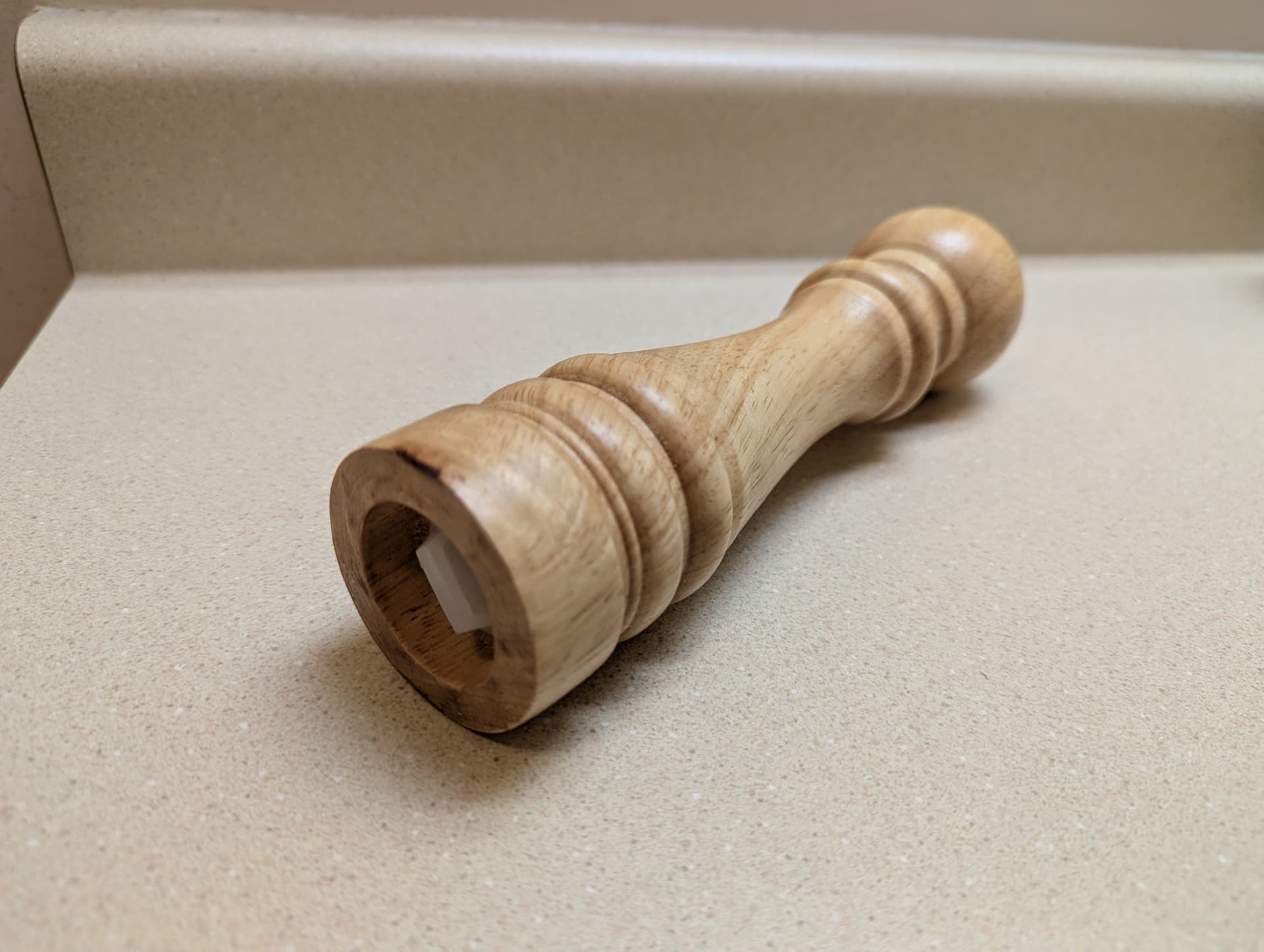
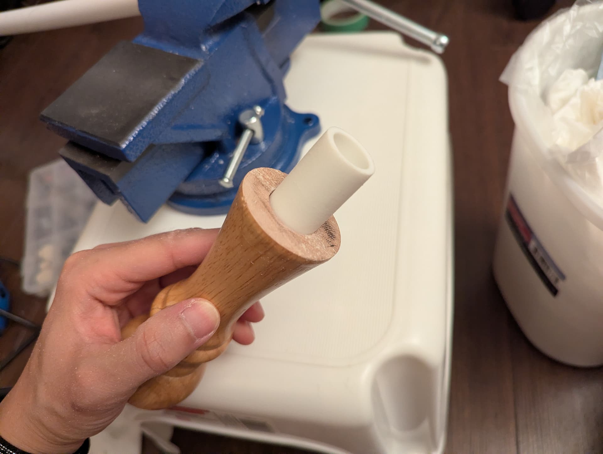
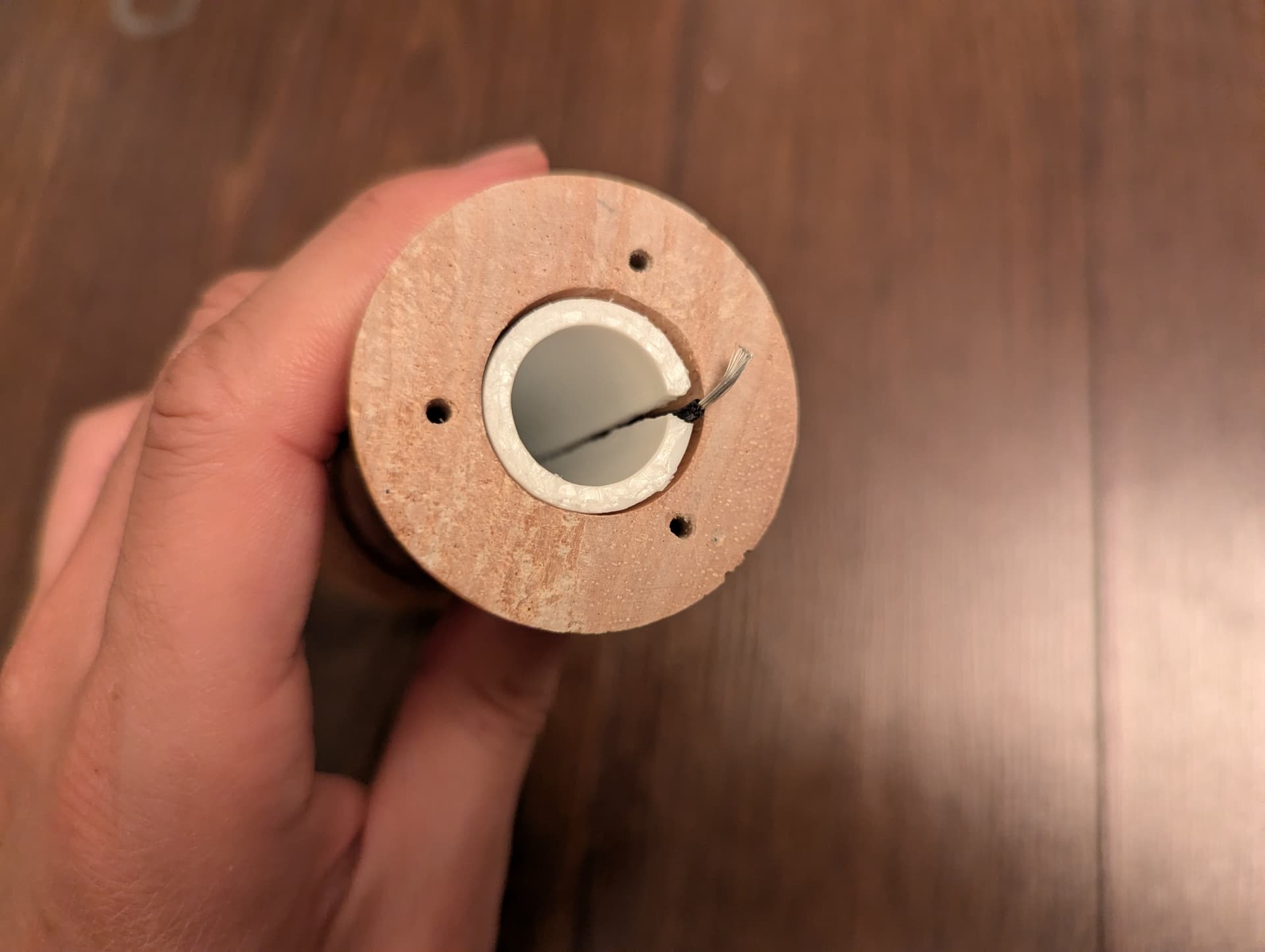
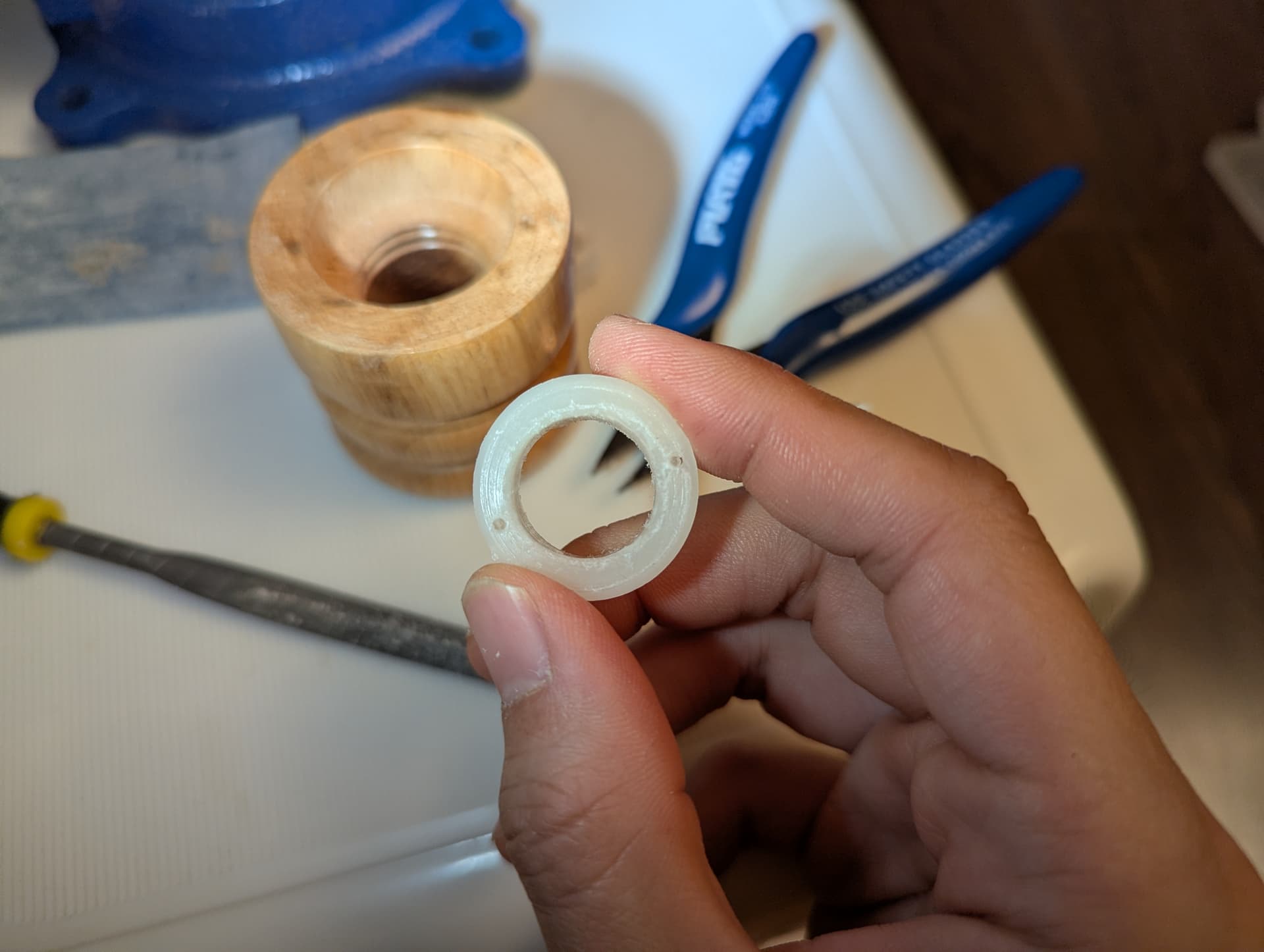
- Small enough inner diameter to hold in the plastic inner tube
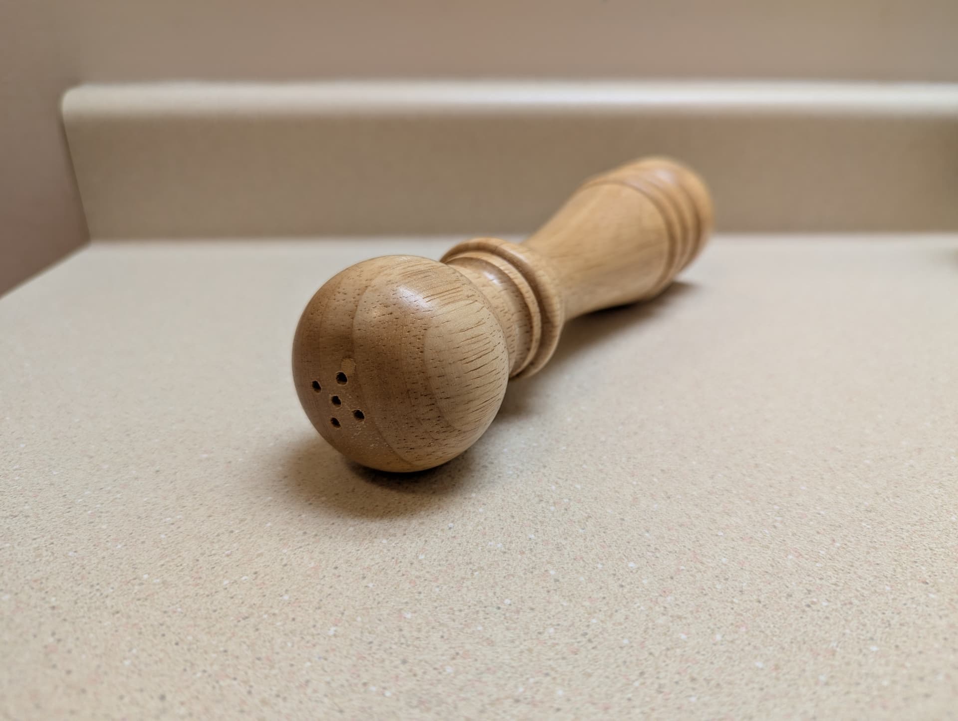
- Large enough outer diameter to sit on the edge of the shaker’s hole
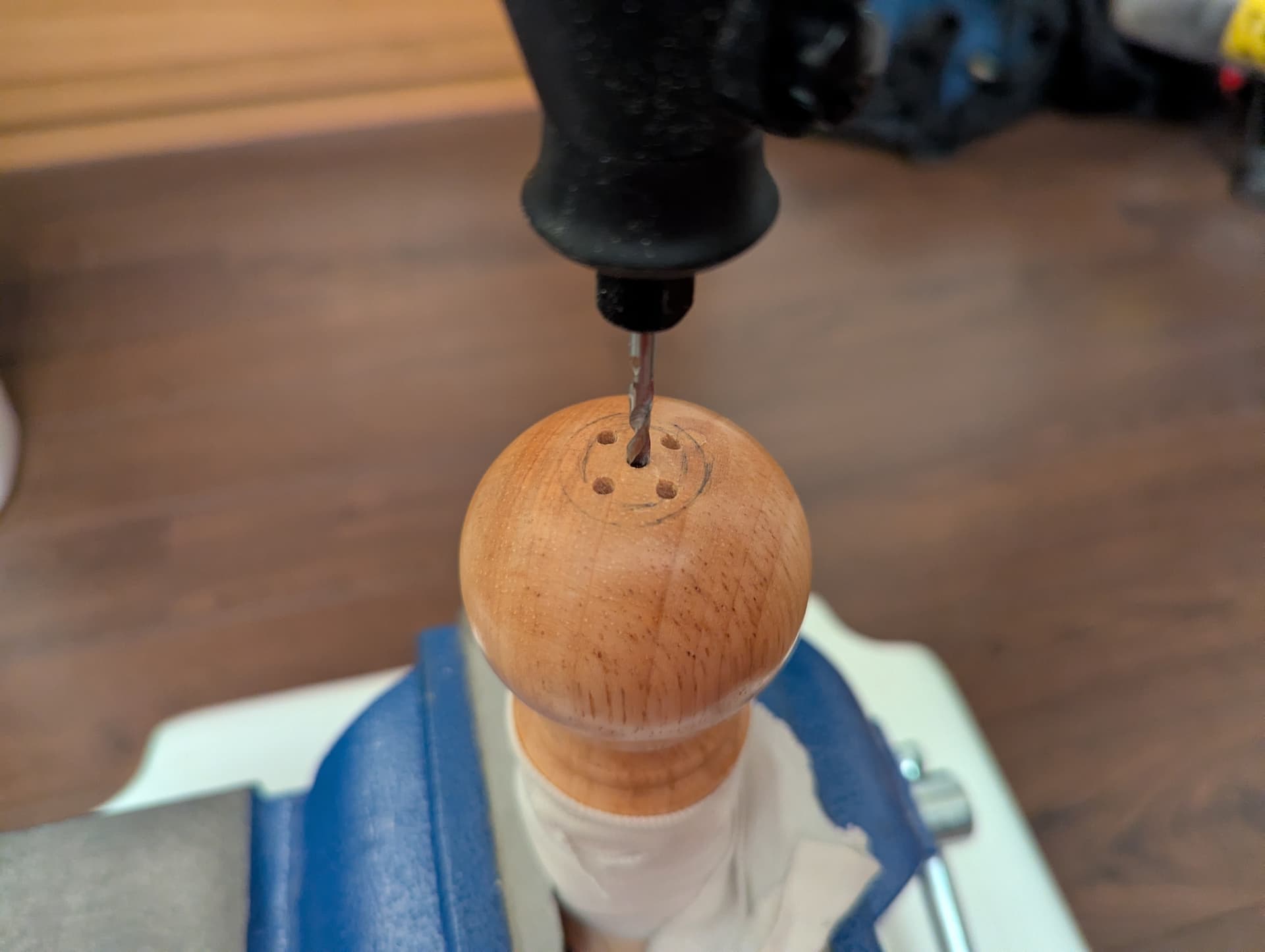
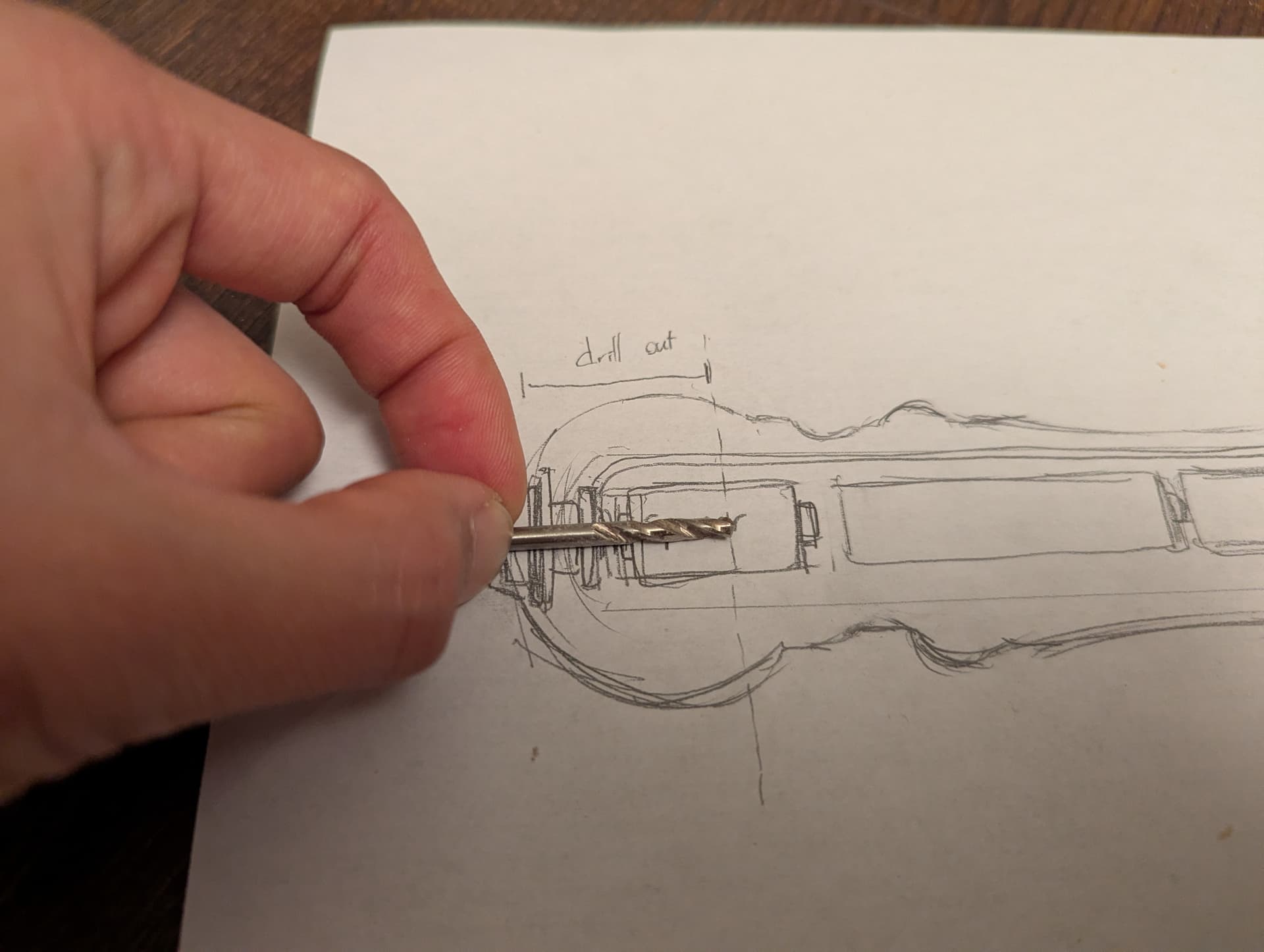
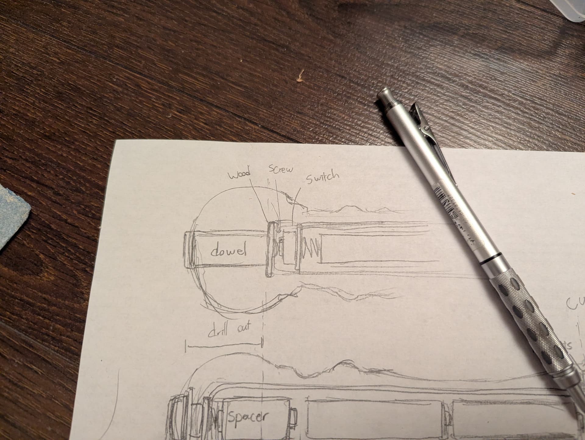
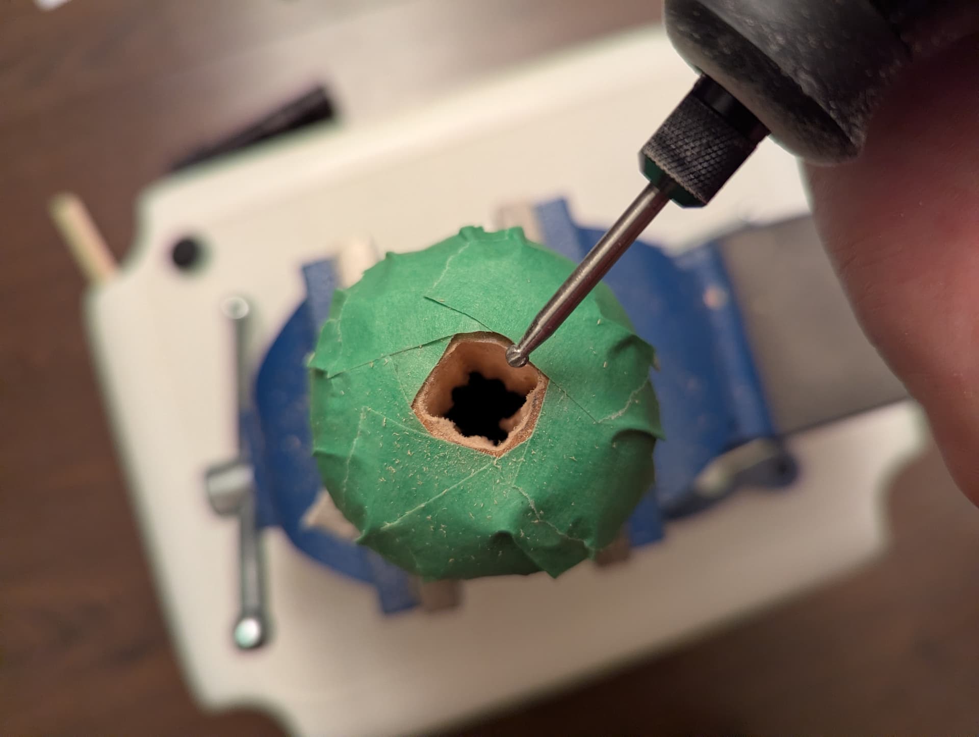
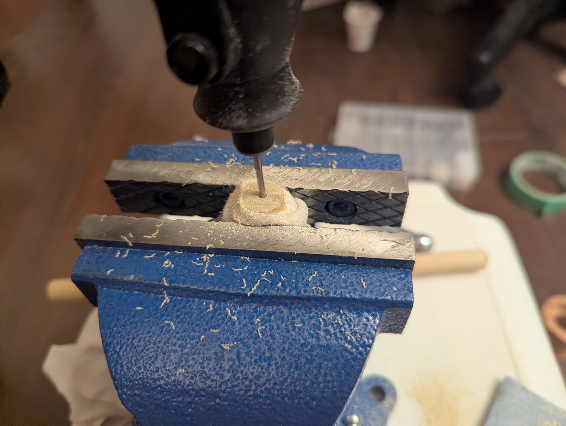
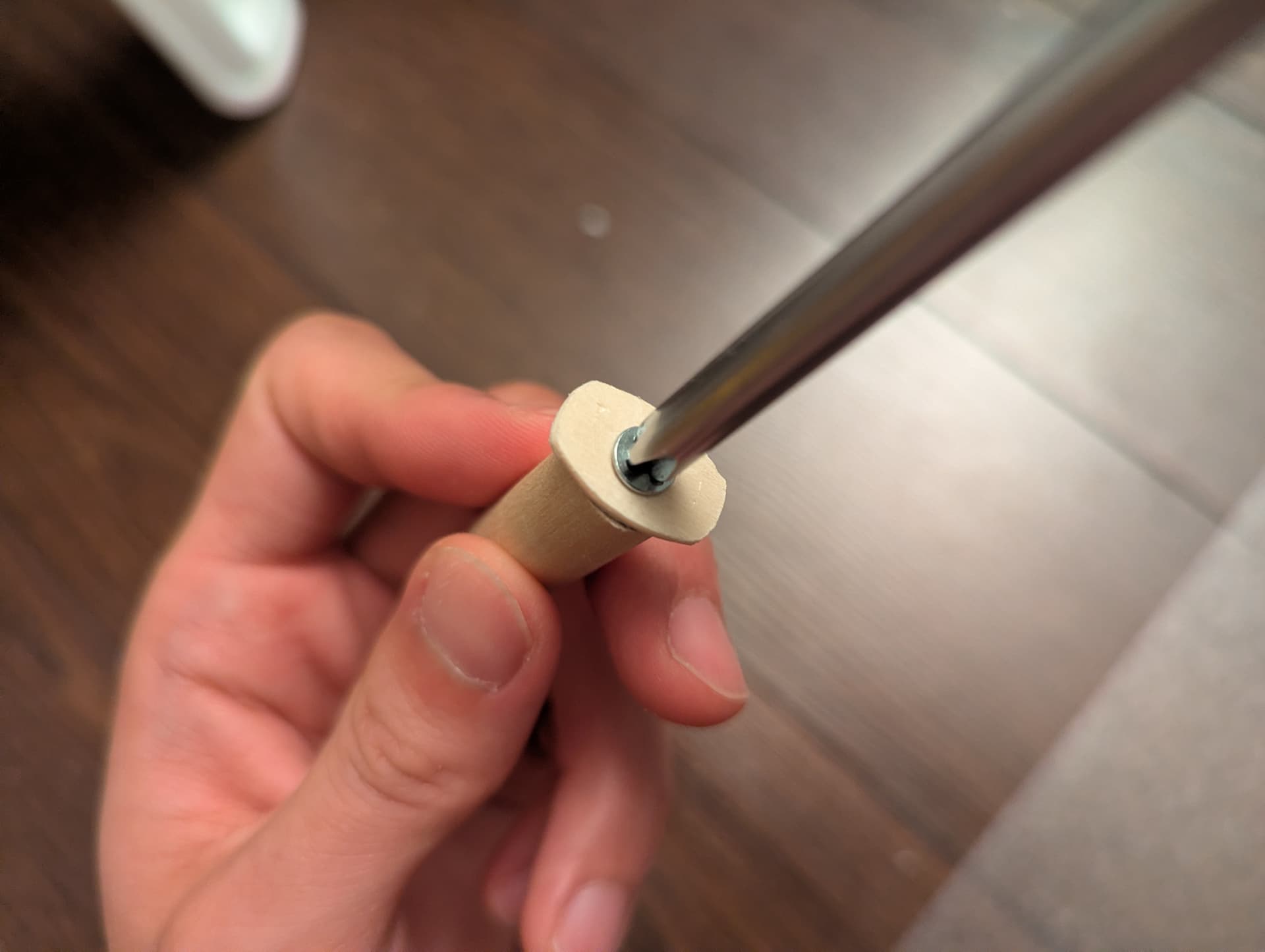
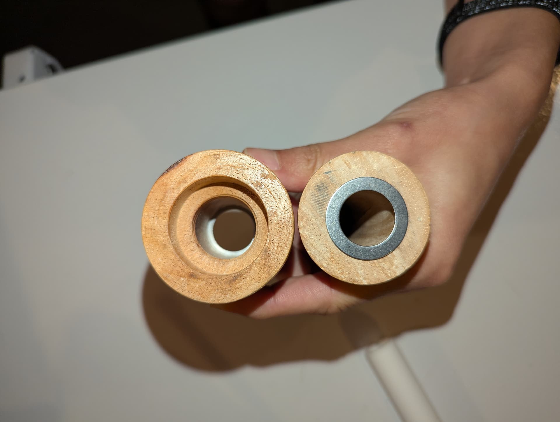
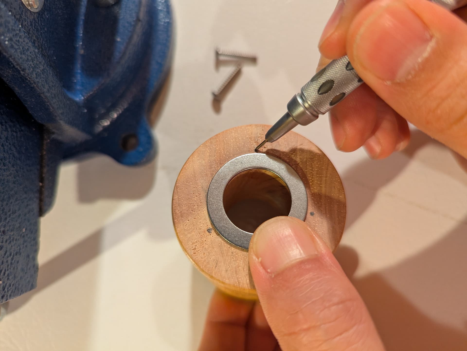
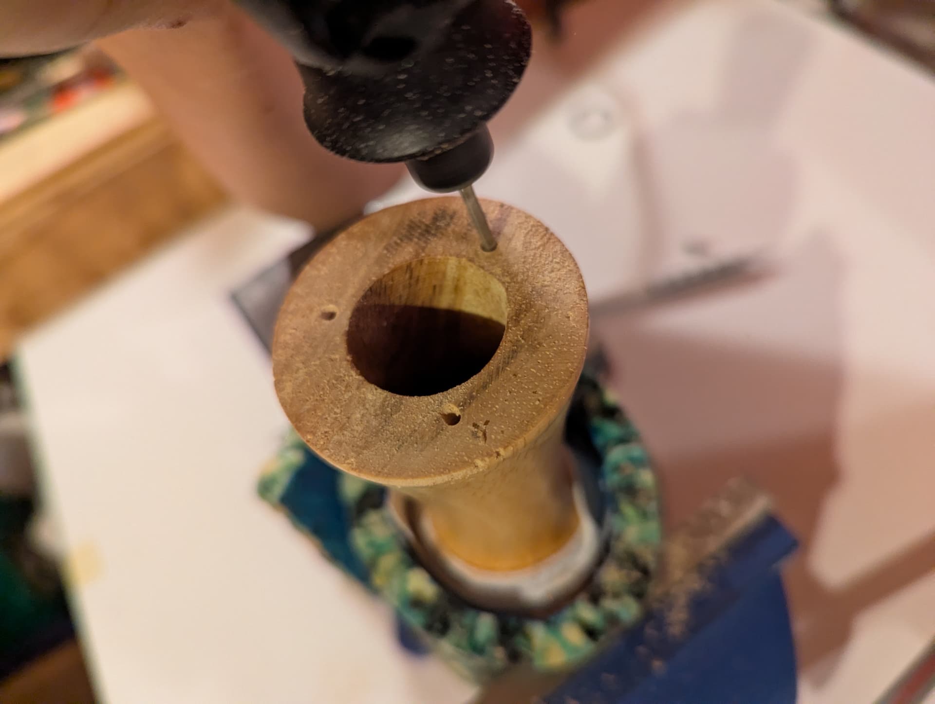
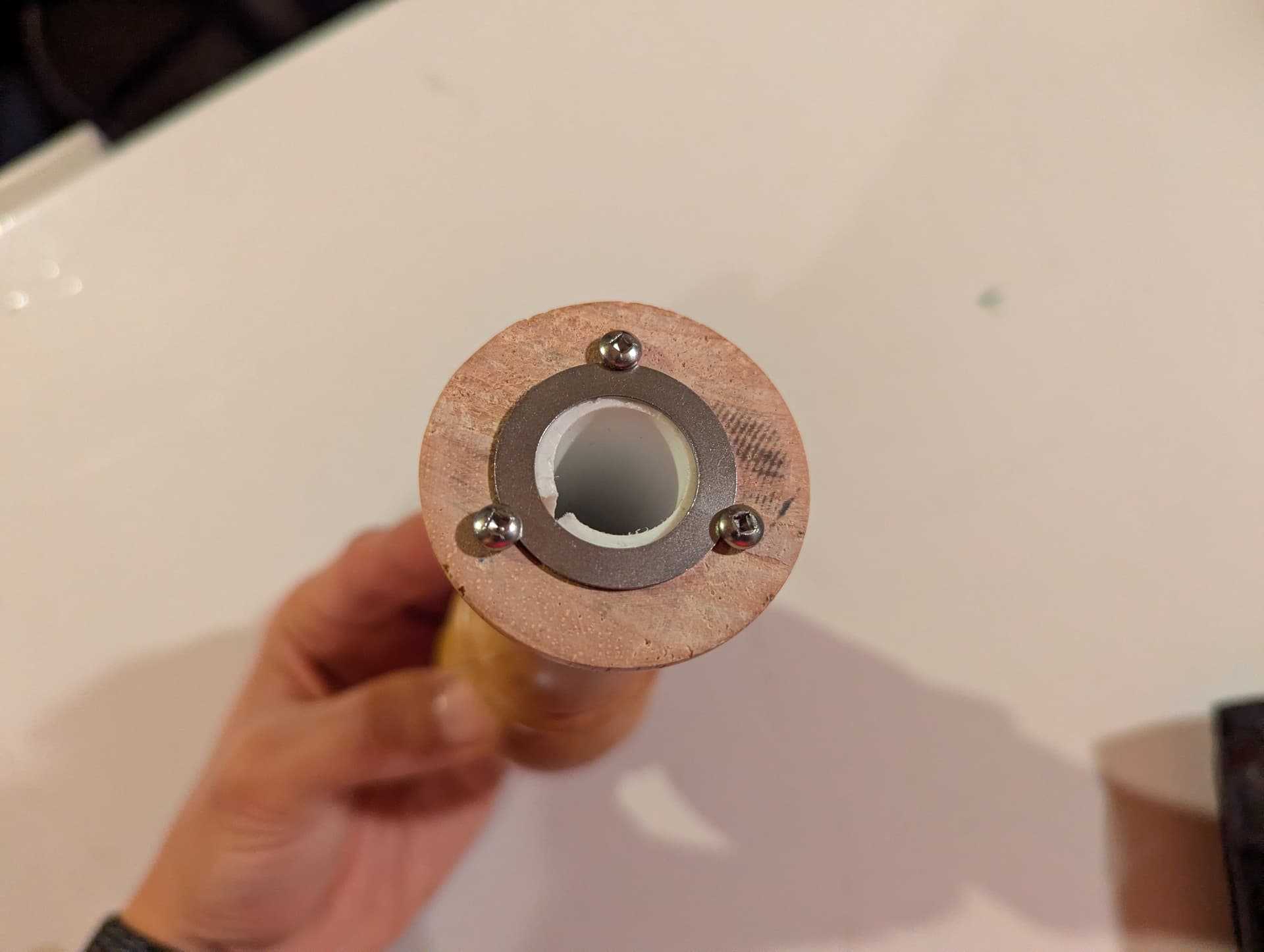
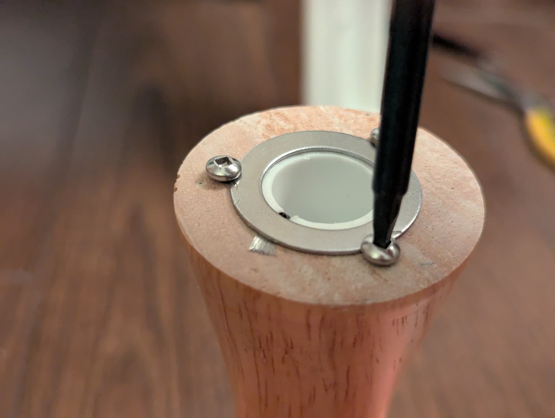
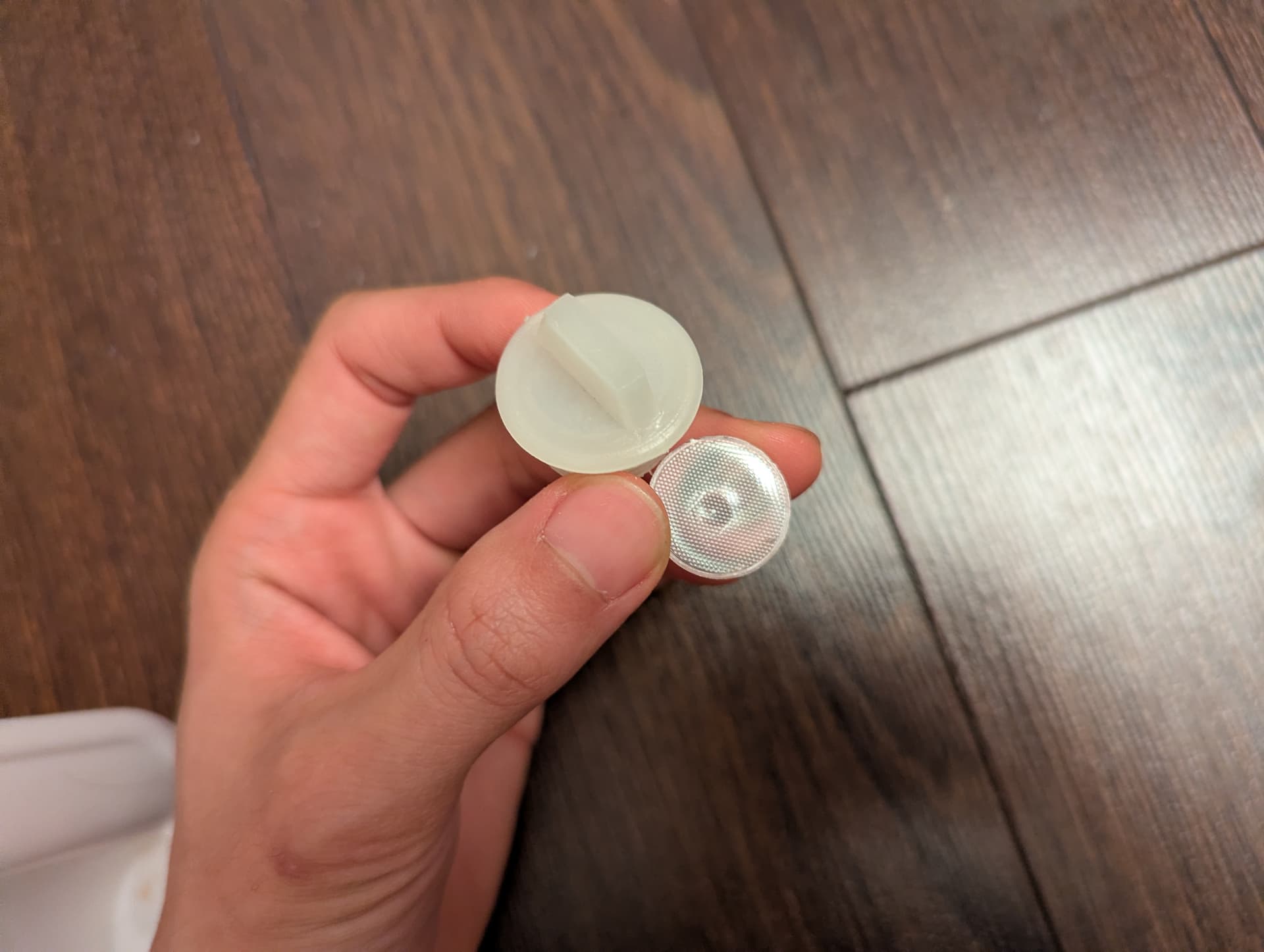
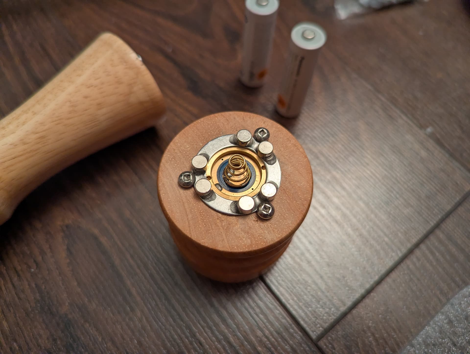
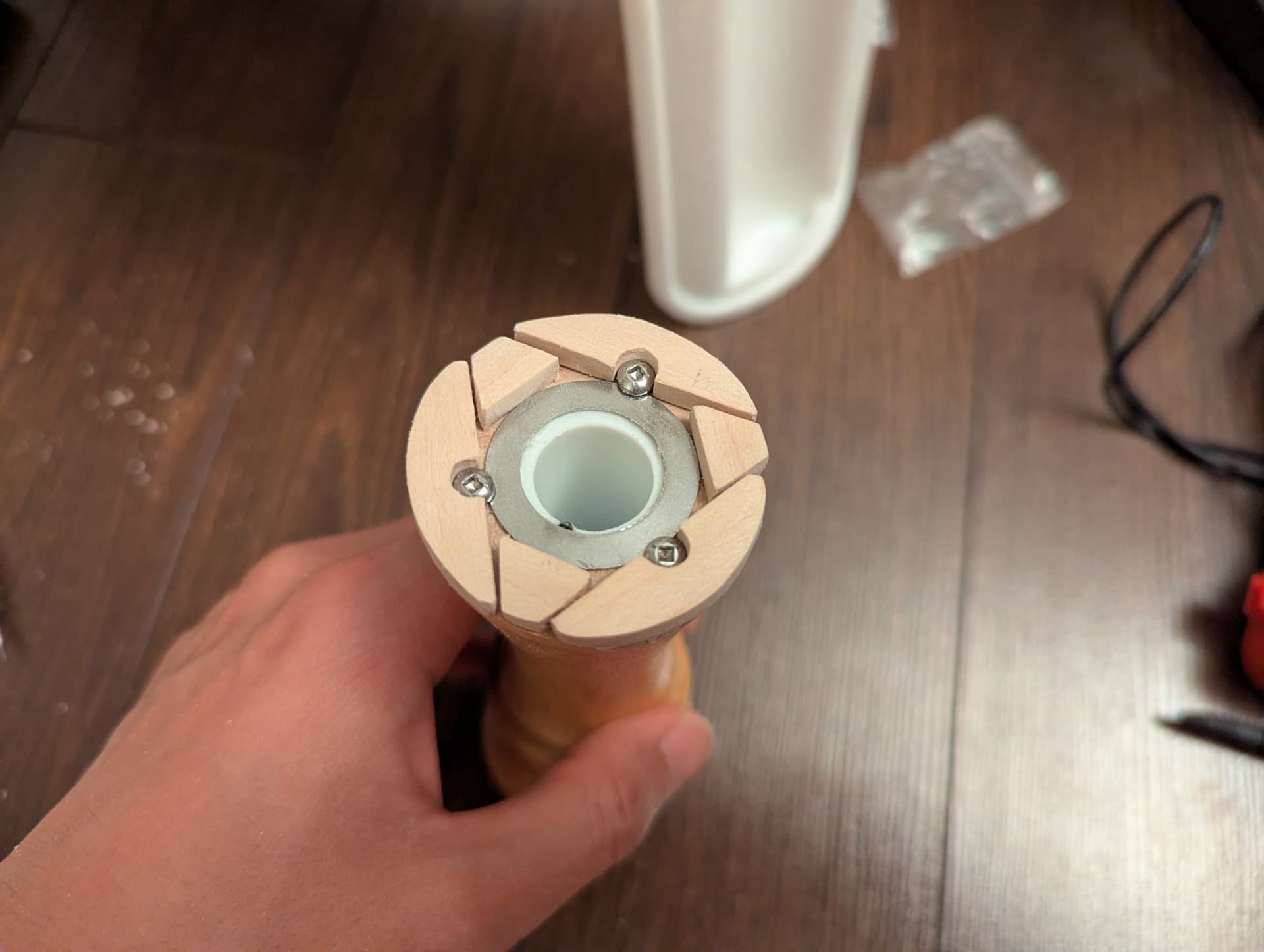
But while the magnets now have something to stick to, how can I attach the washers to each end of the light? That’s thankfully a much easier problem to solve, with screws:
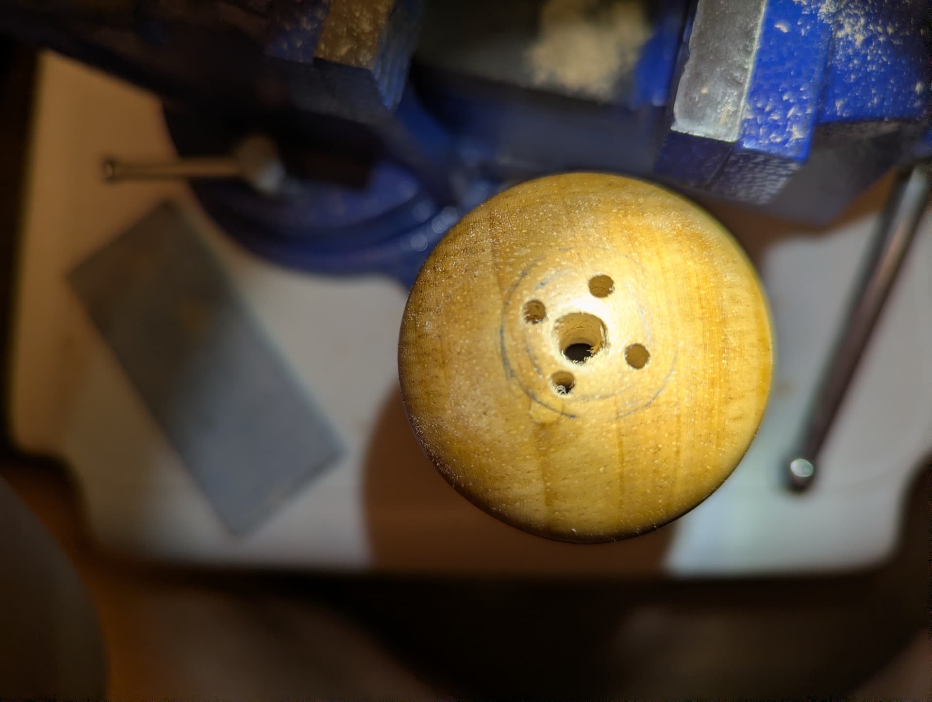
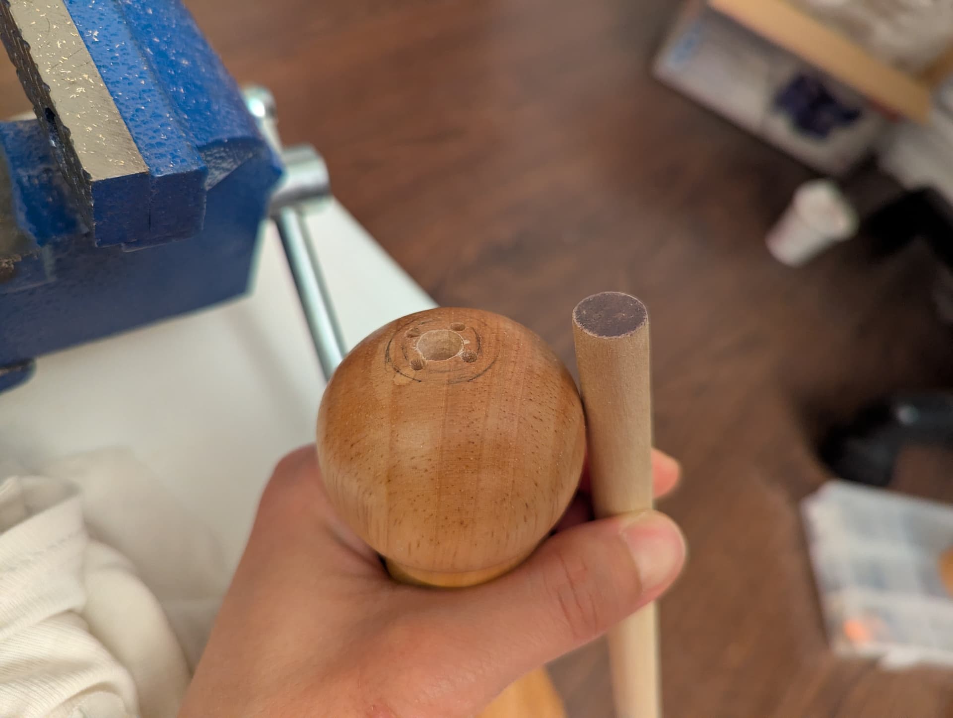
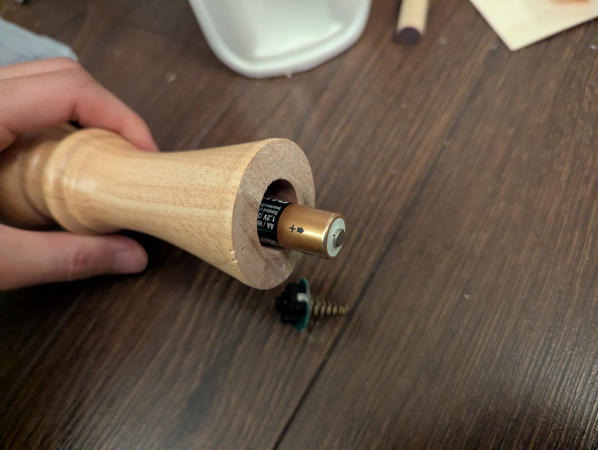
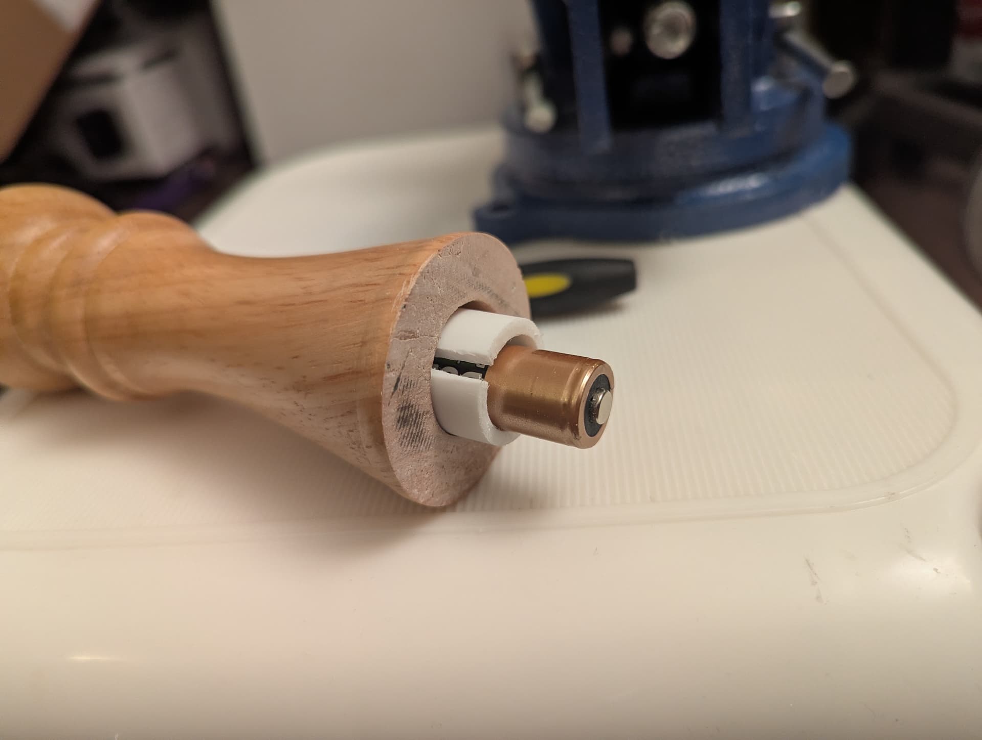
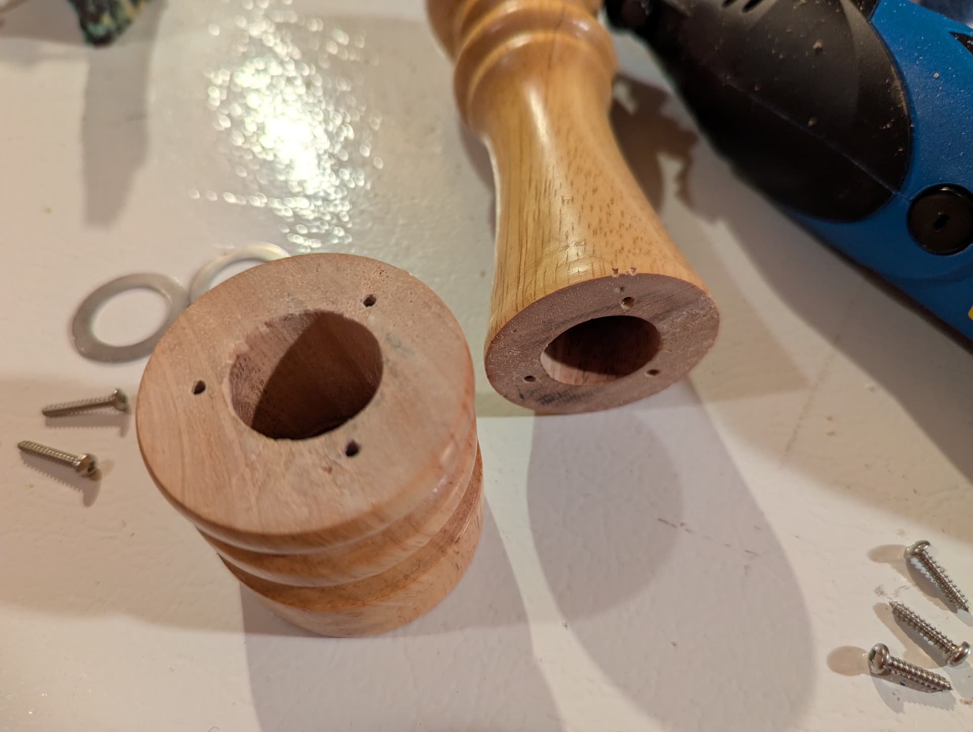
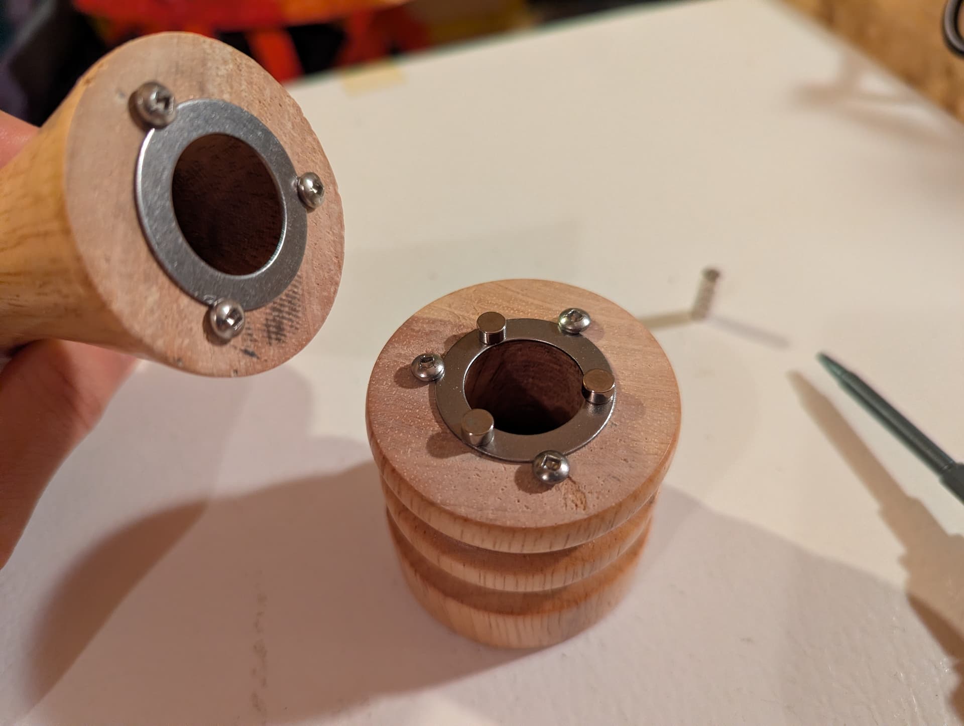
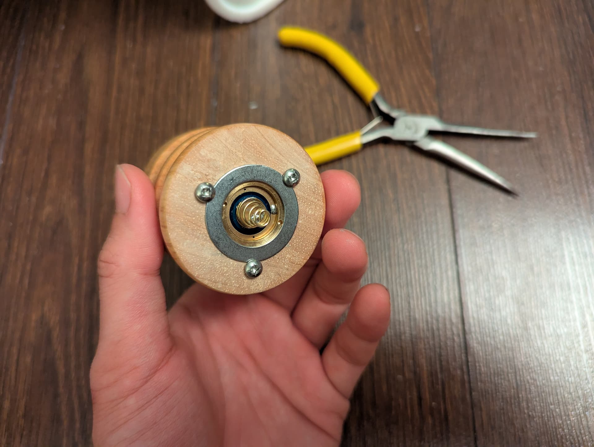
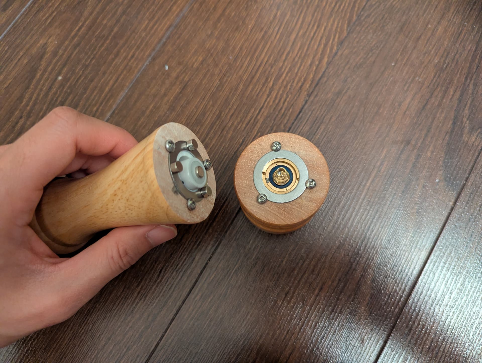
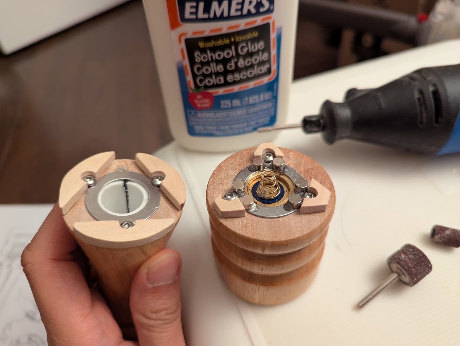
With the pilot holes drilled, everything can be assembled and we can see where the magnets will go:
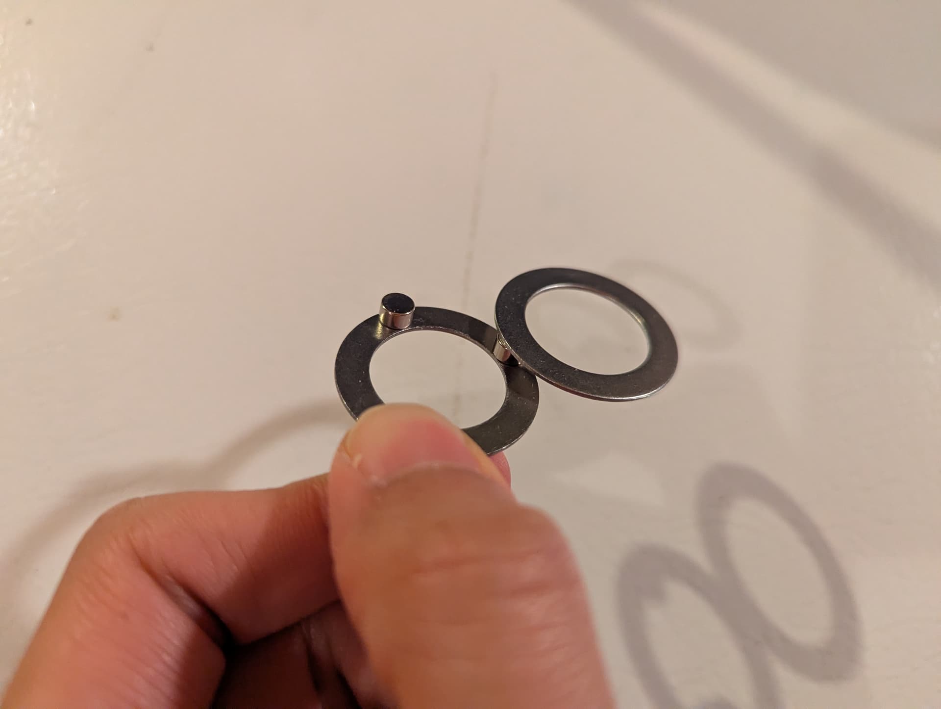
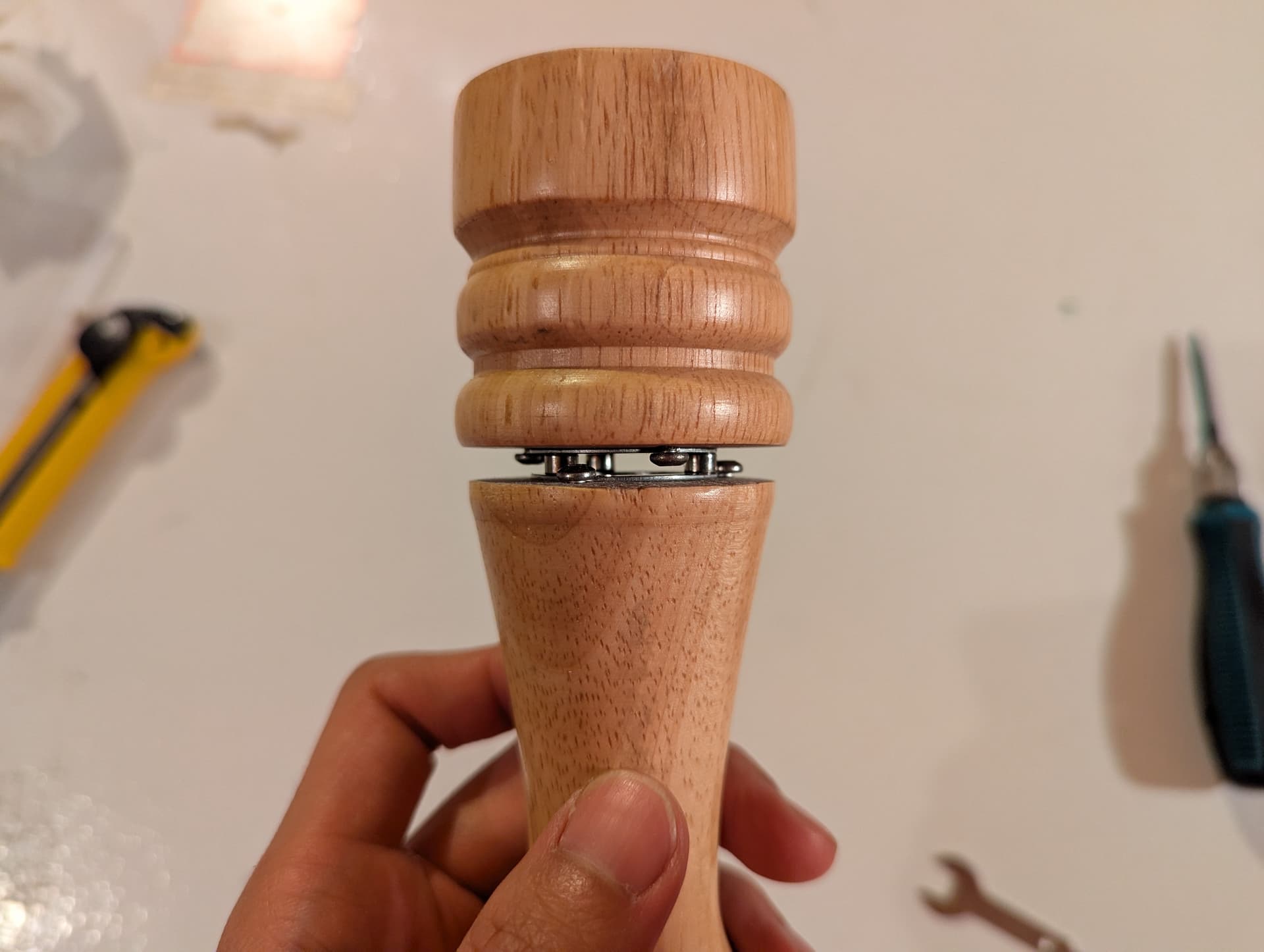
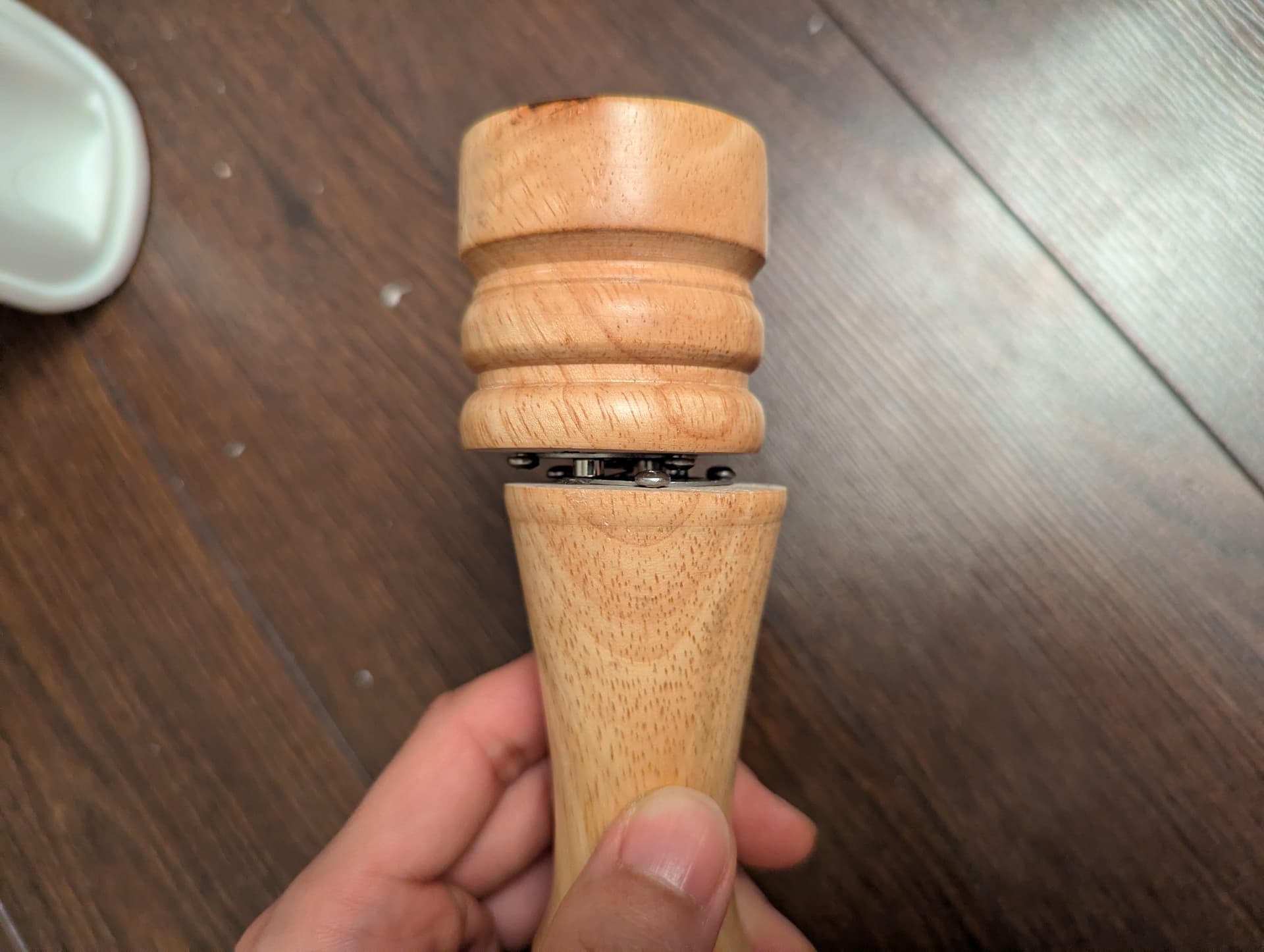
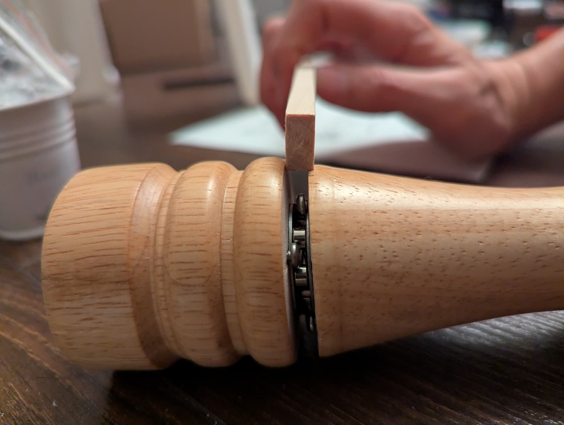
The magnets and washers do a good job of both keeping the tail assembly together, and the two flashlight ends connected!
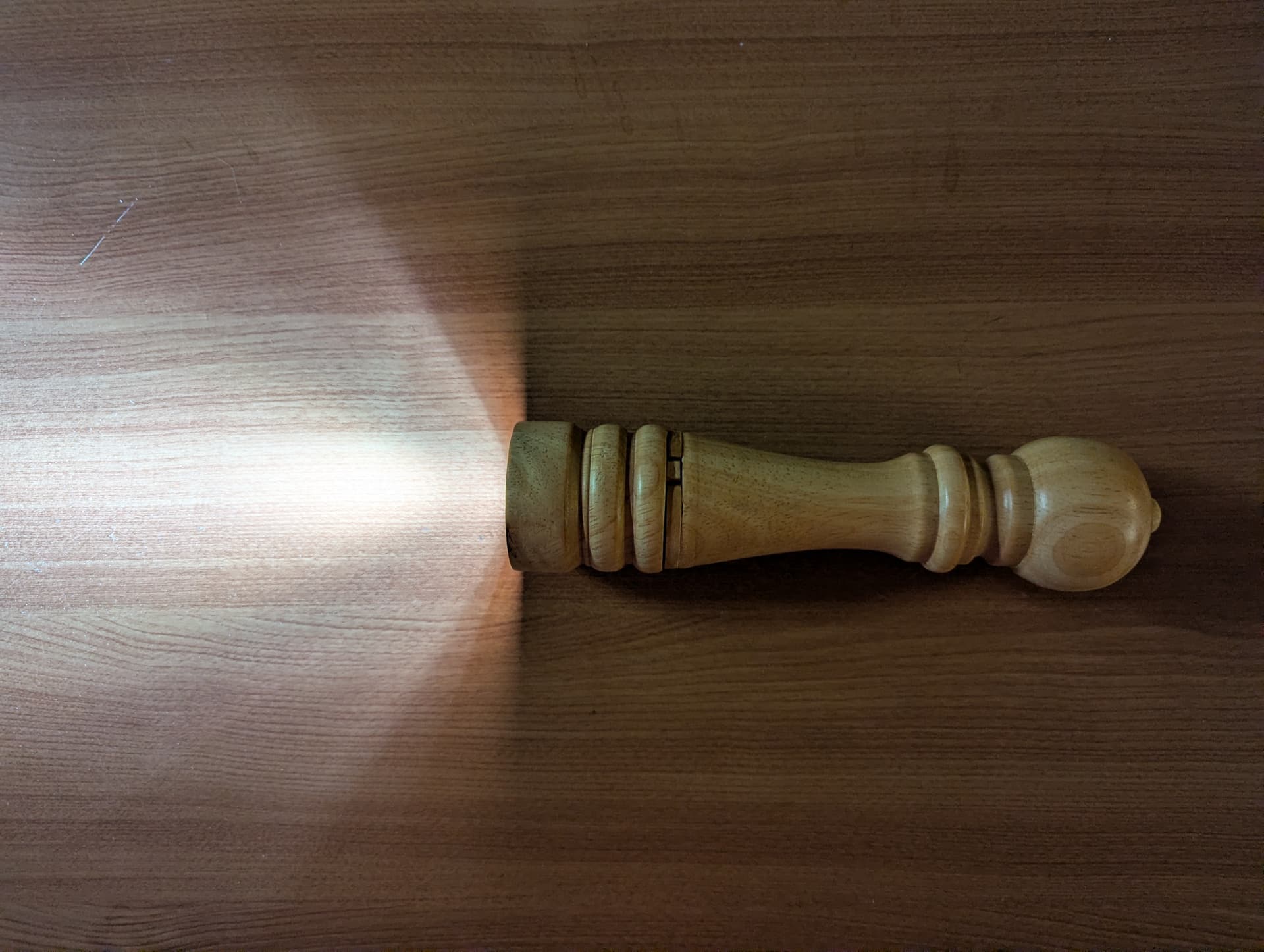
This light is starting to come together! Except, well, it doesn’t actually light up.
So now that we have the structure defined - it’s time to add the “light” to my flashlight.
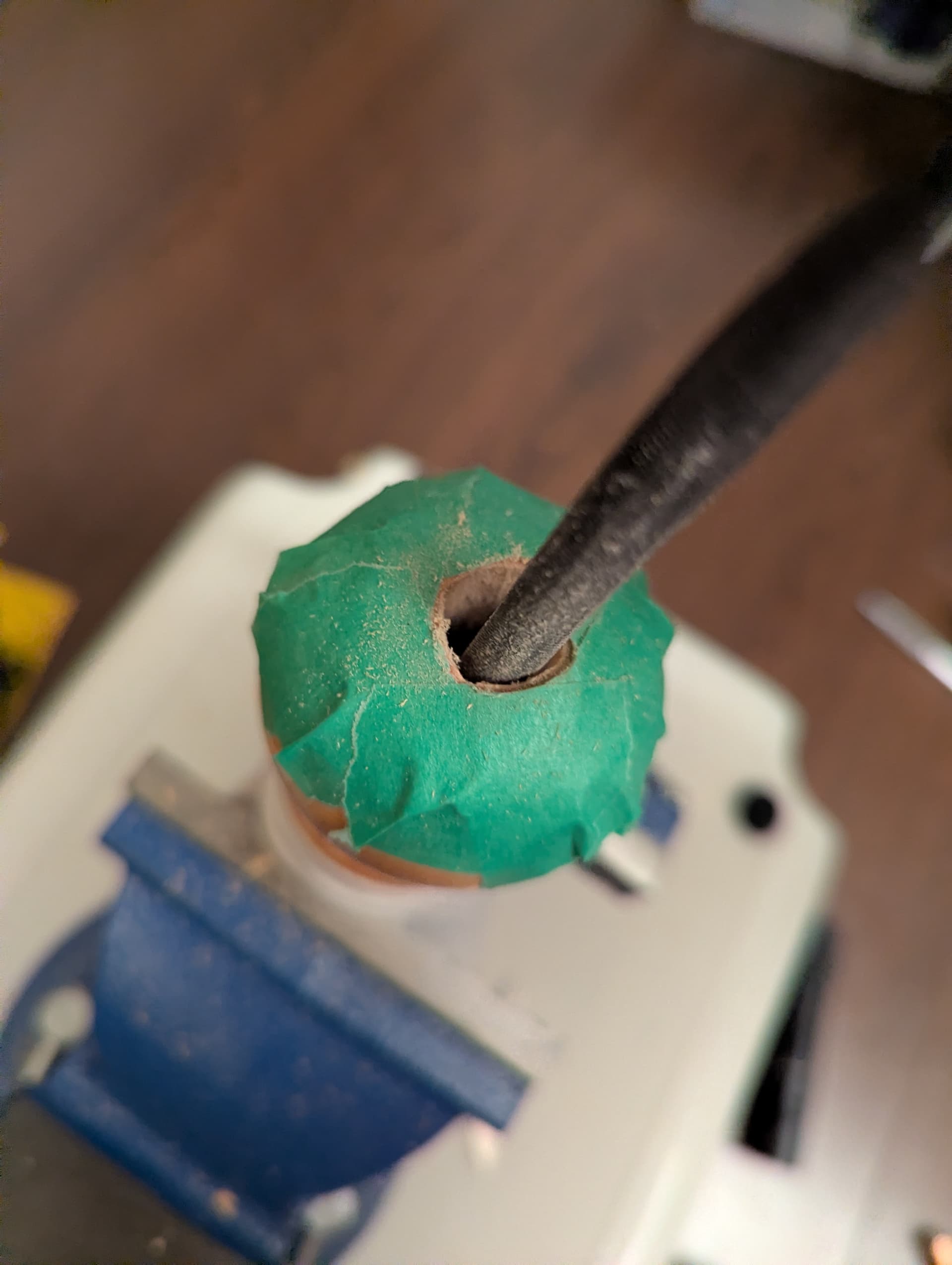
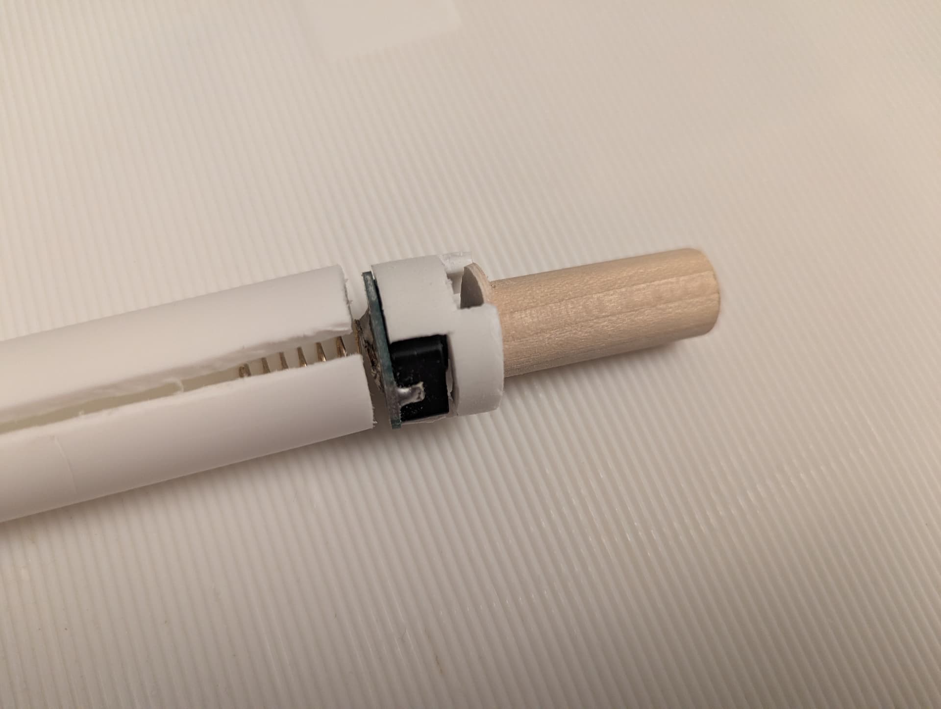
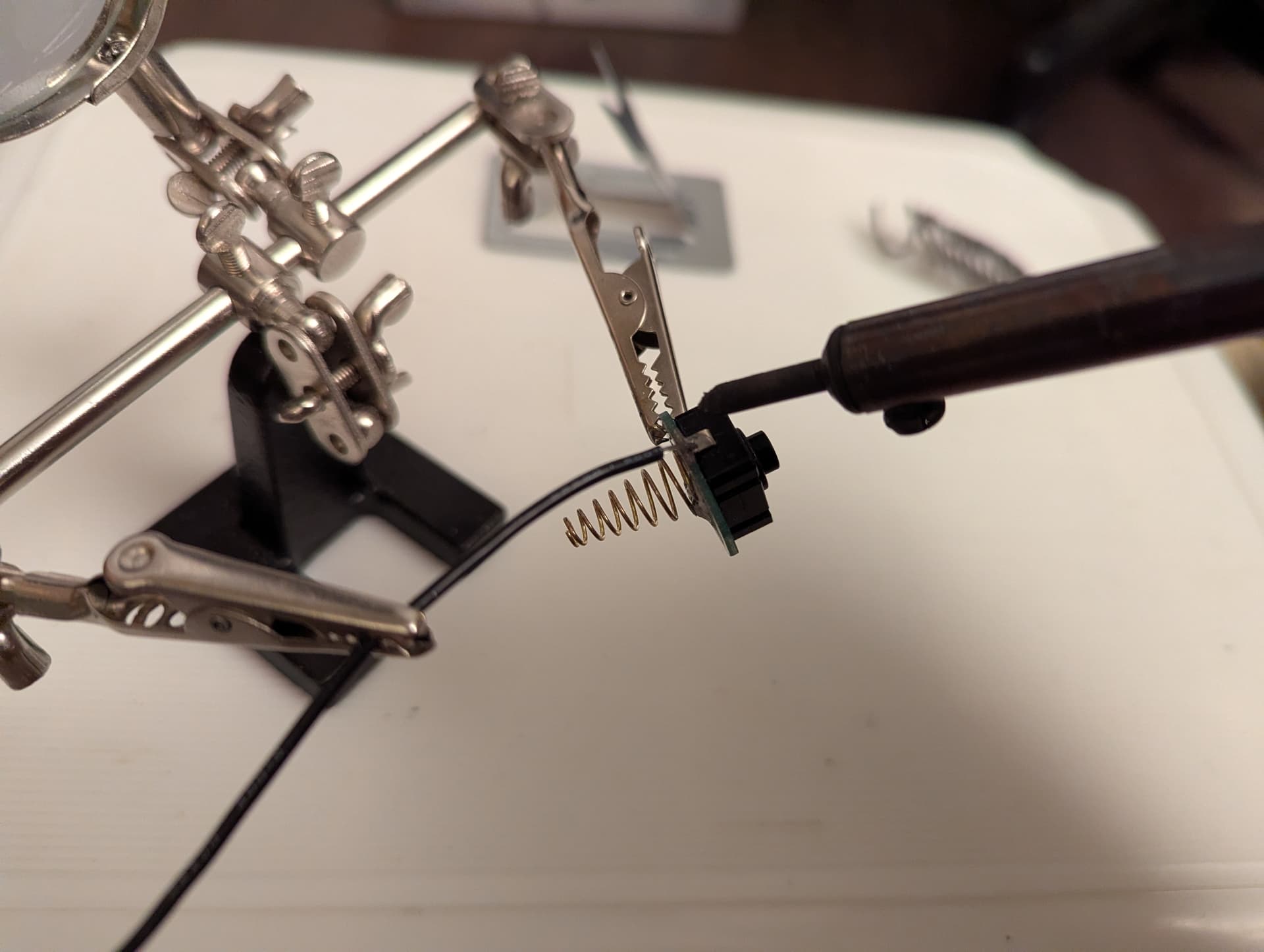
First, I need to ensure electrical continuity in the tail:
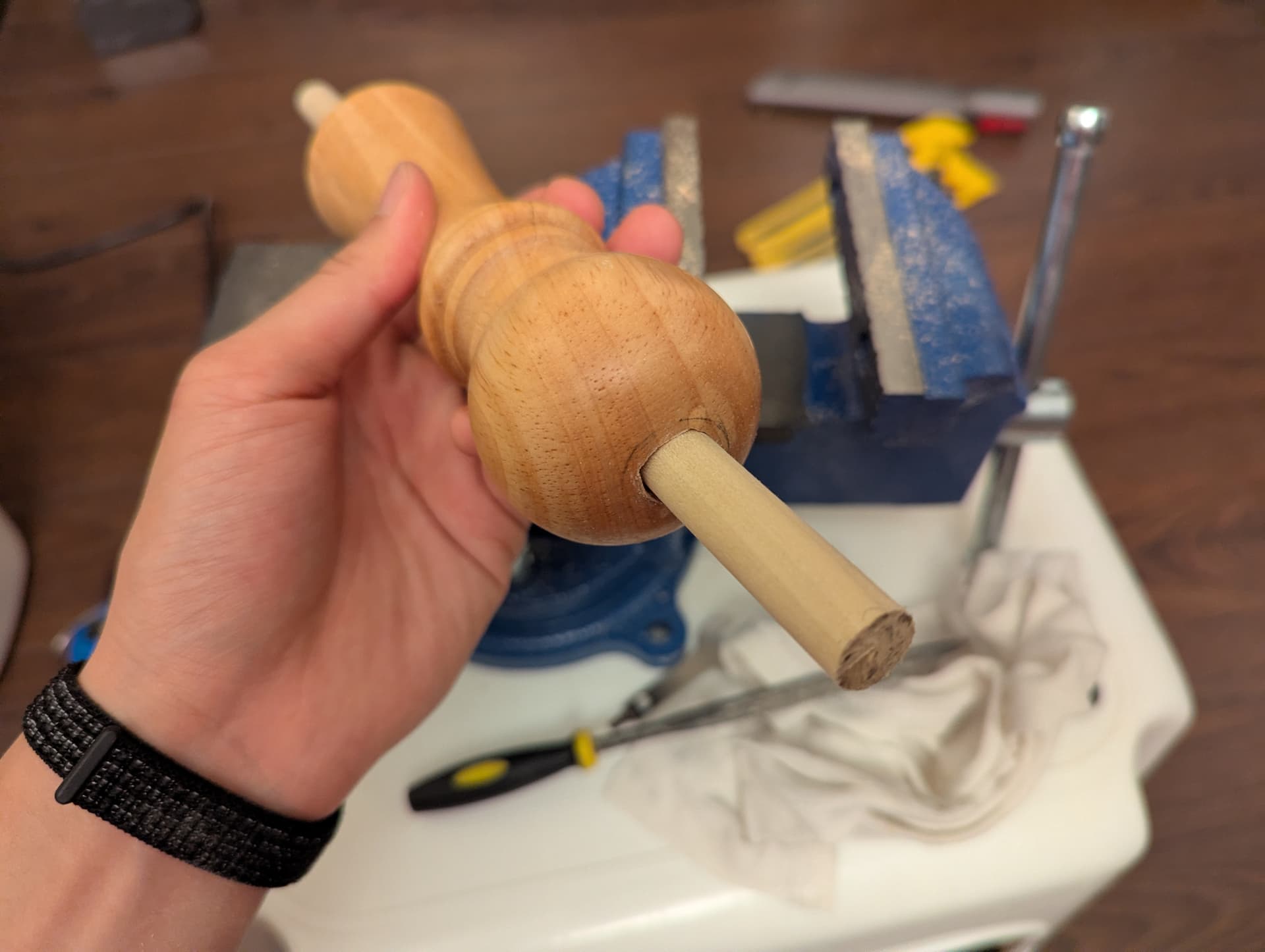
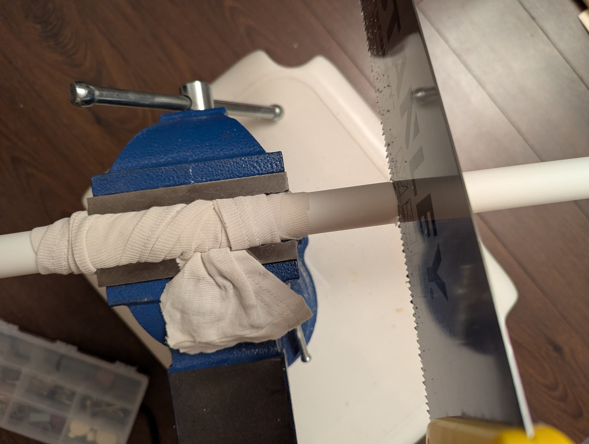
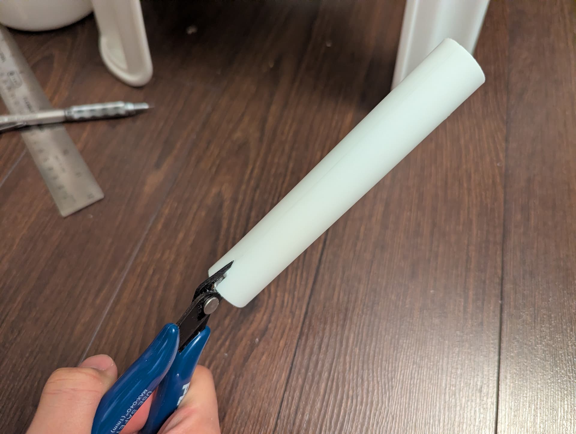
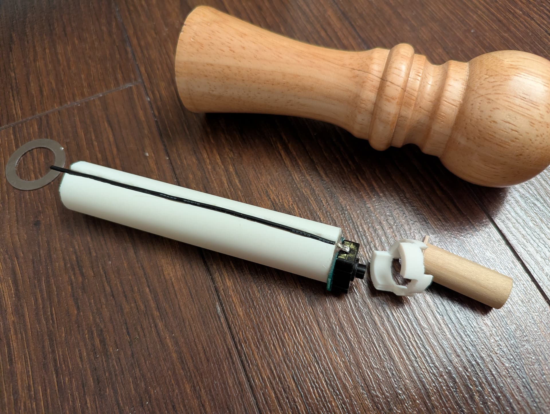
After soldering a wire to the tail switch, it can be run up the body of the light to reach the head. You can see how the channel I cut in the PEX pipe earlier works excellently for routing the wire to the front while segregating it from the batteries.
And with the washer screwed down, the tail is electrically complete!
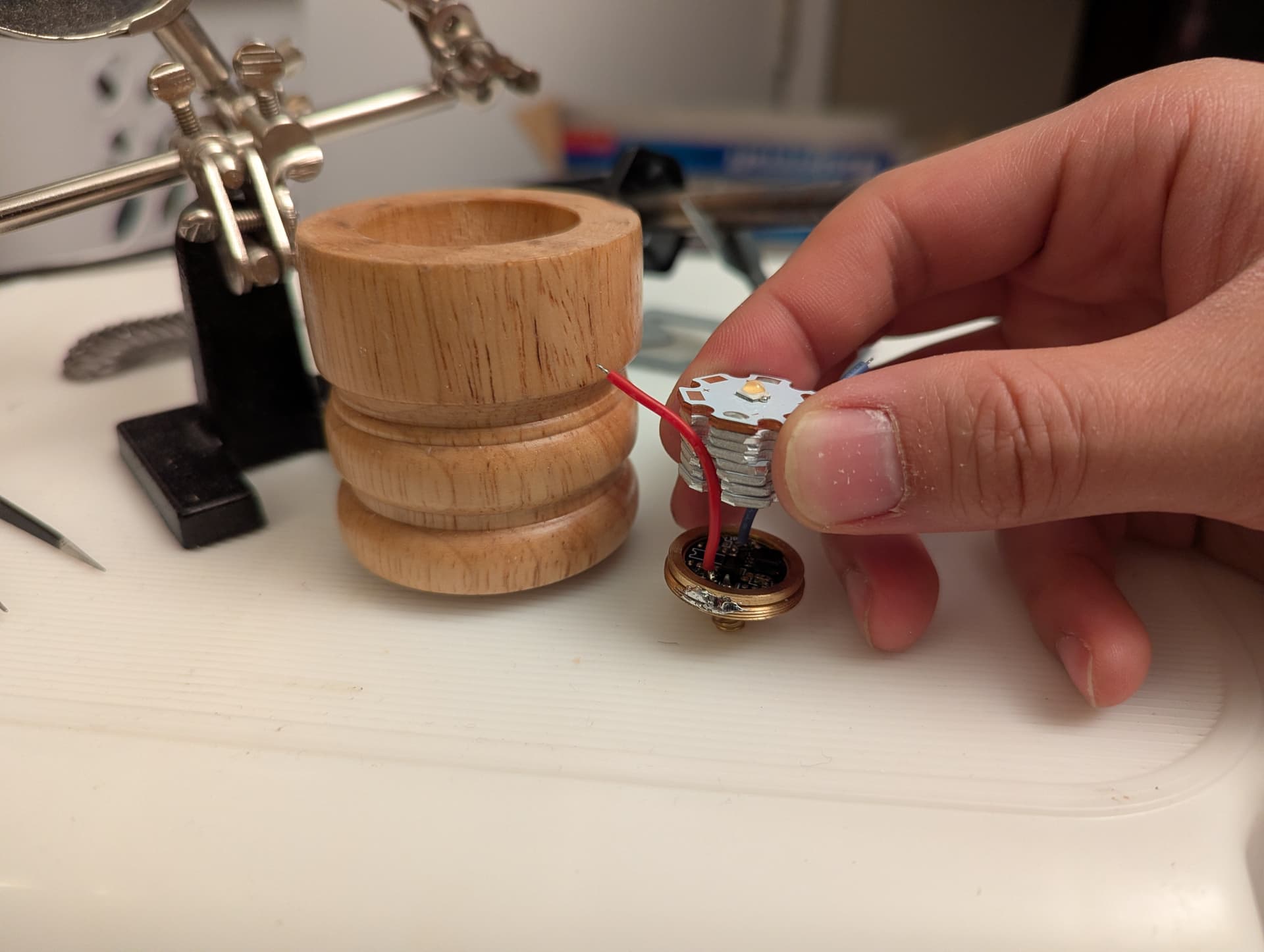
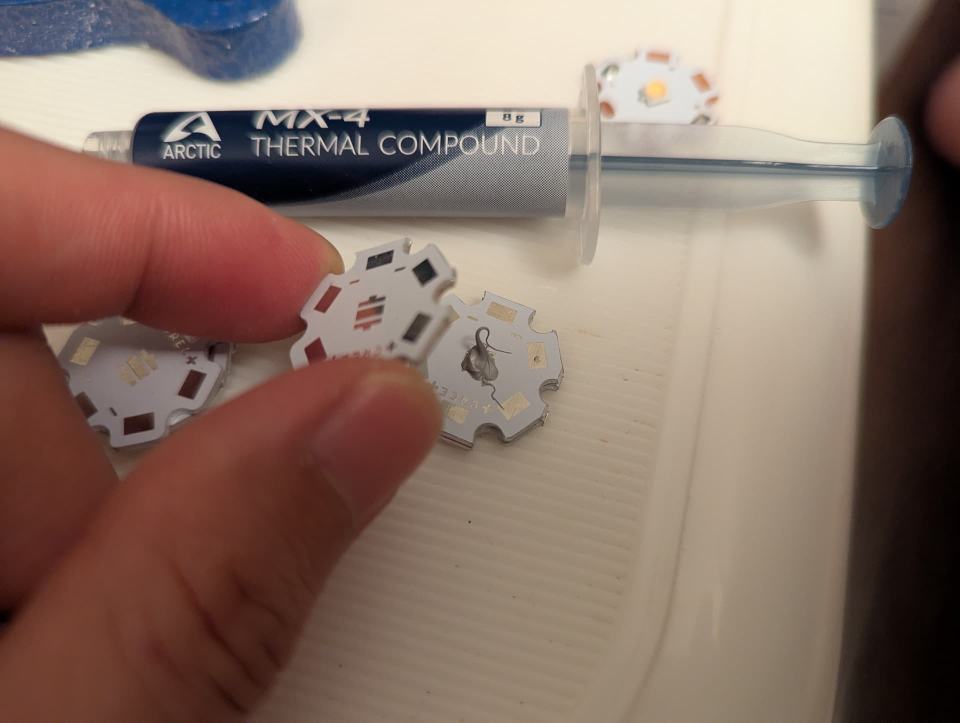
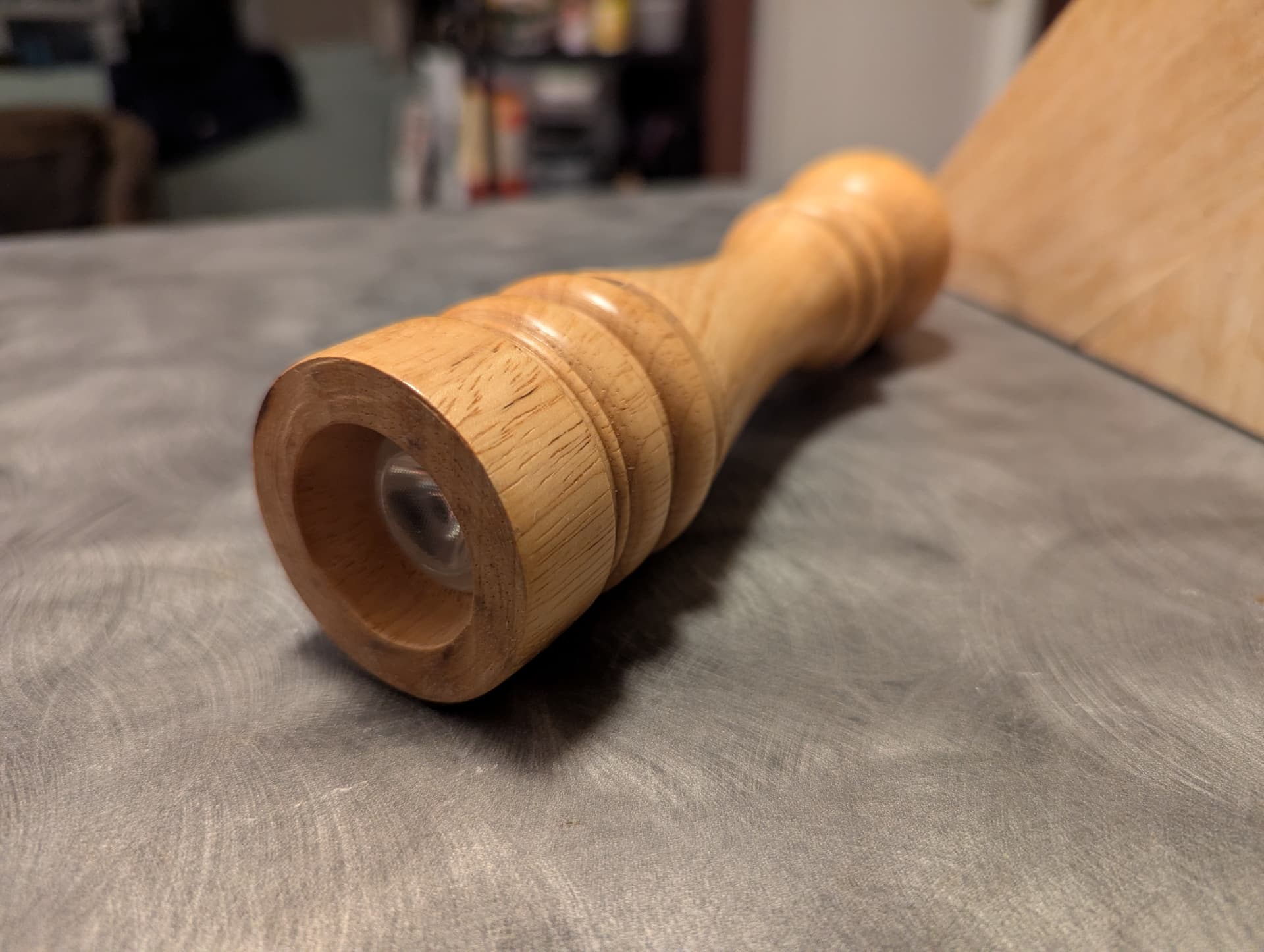
With the tail dealt with, I can now focus on the head of the light! I anticipate this to be an interesting sandwich of PCBs and spacers, with some fiddling and filing needed to fit.
The emitter I chose is the Nichia 519A, for its pleasing tint and high CRI.
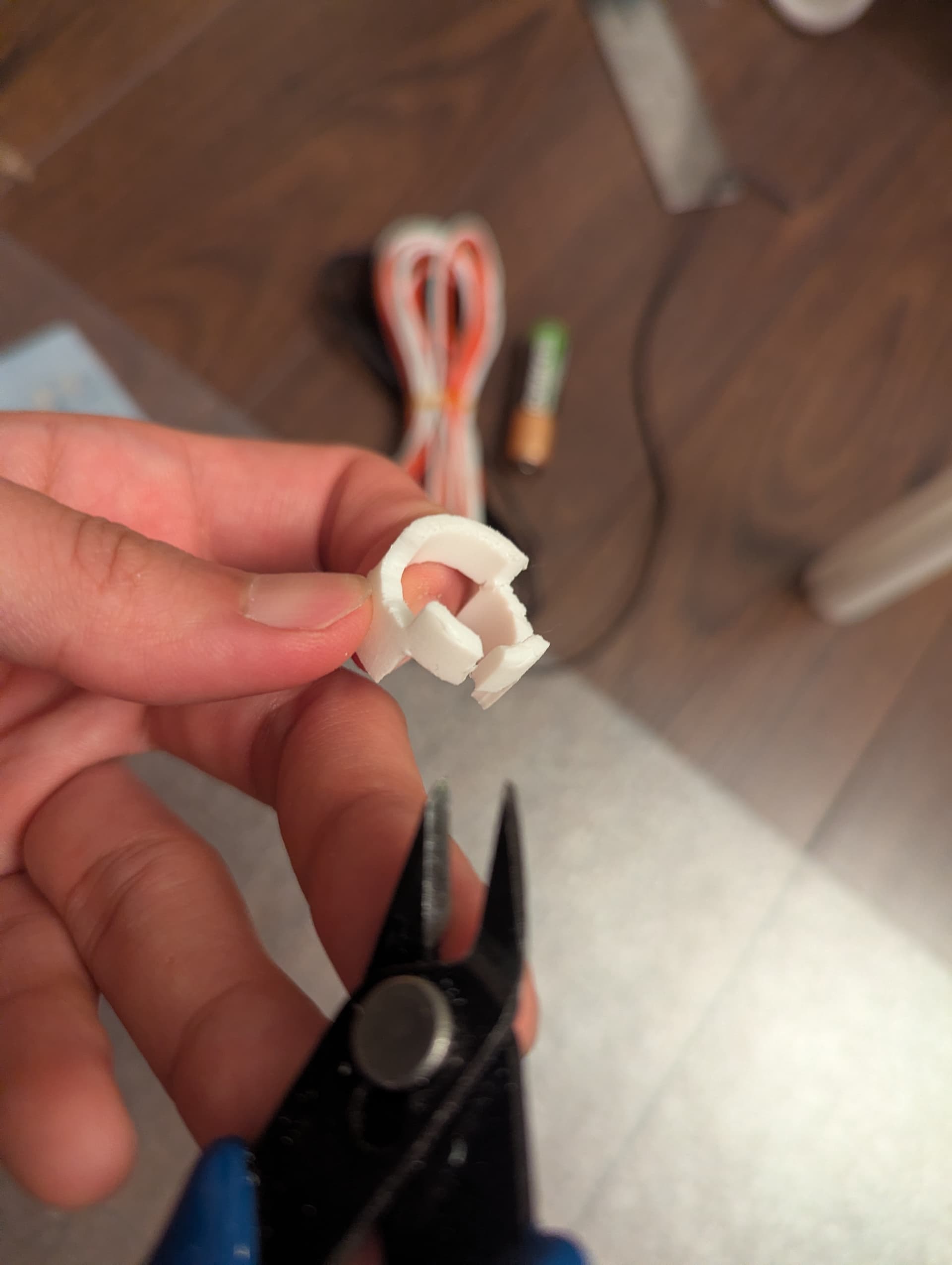
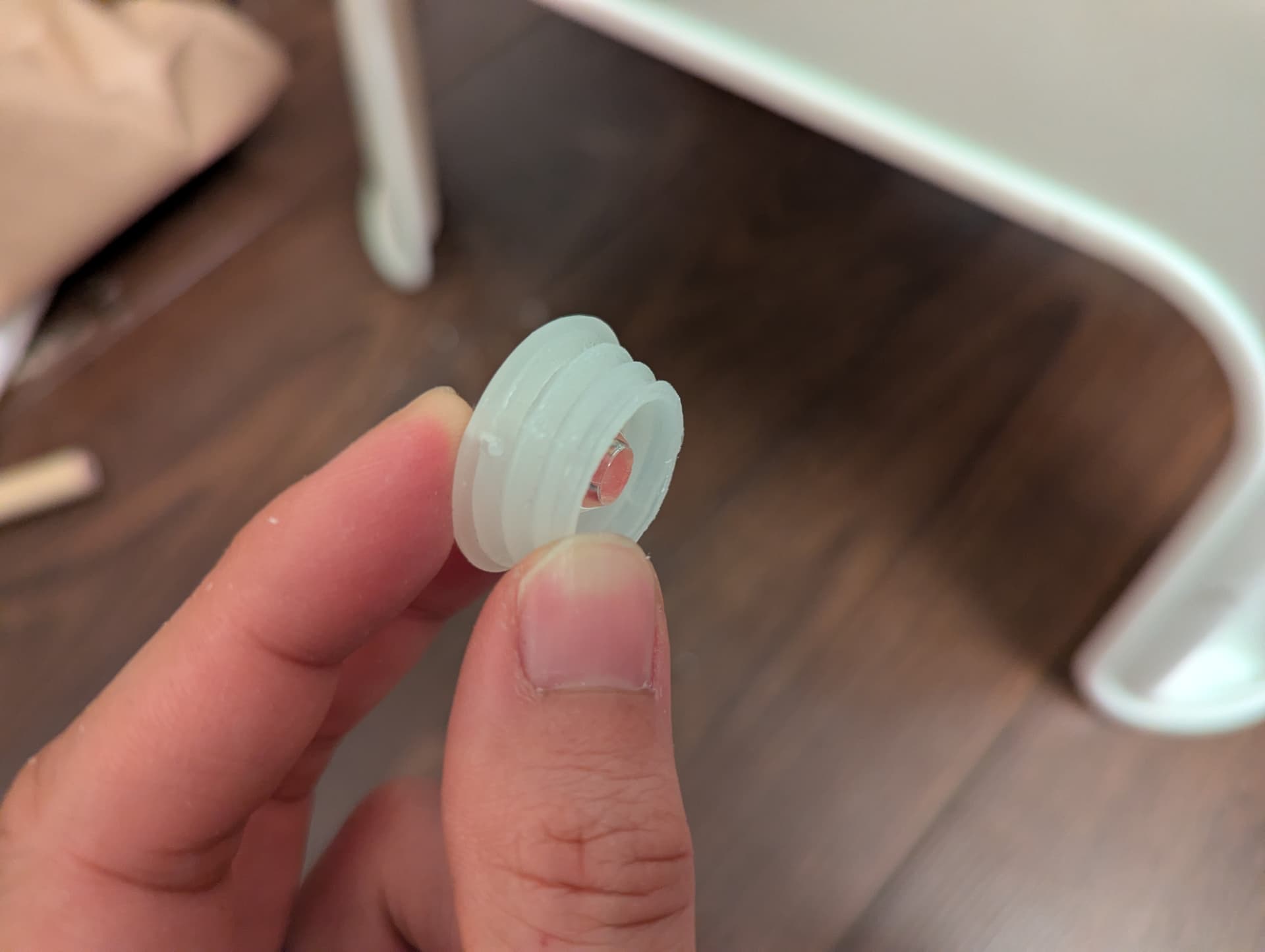
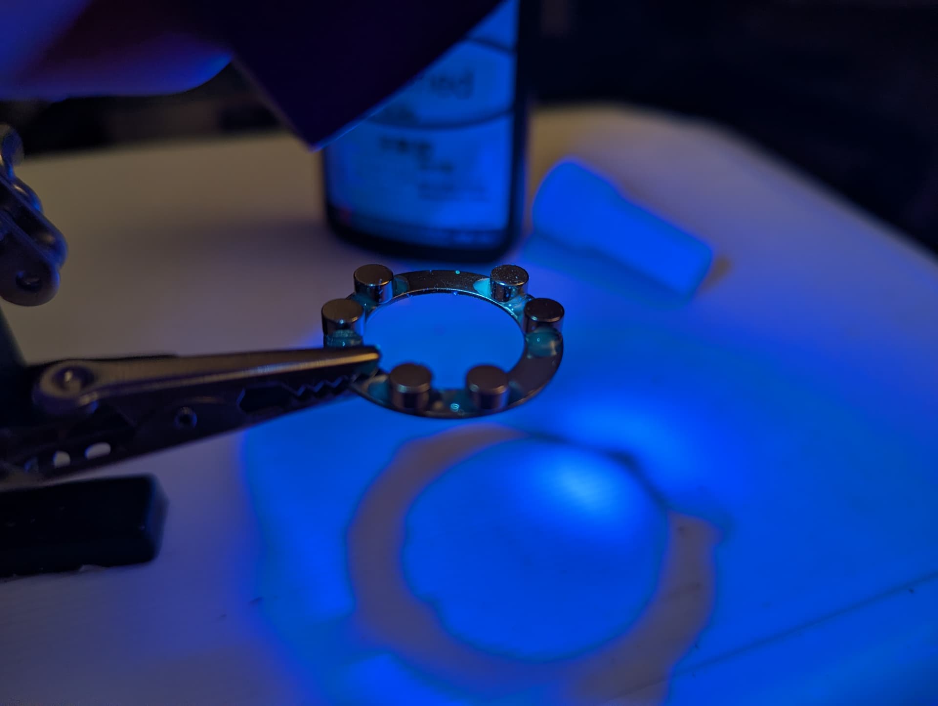
To prep the driver, I soldered a retaining ring to my driver to give it a bit more diameter, and protect it from being crushed in the assembly.
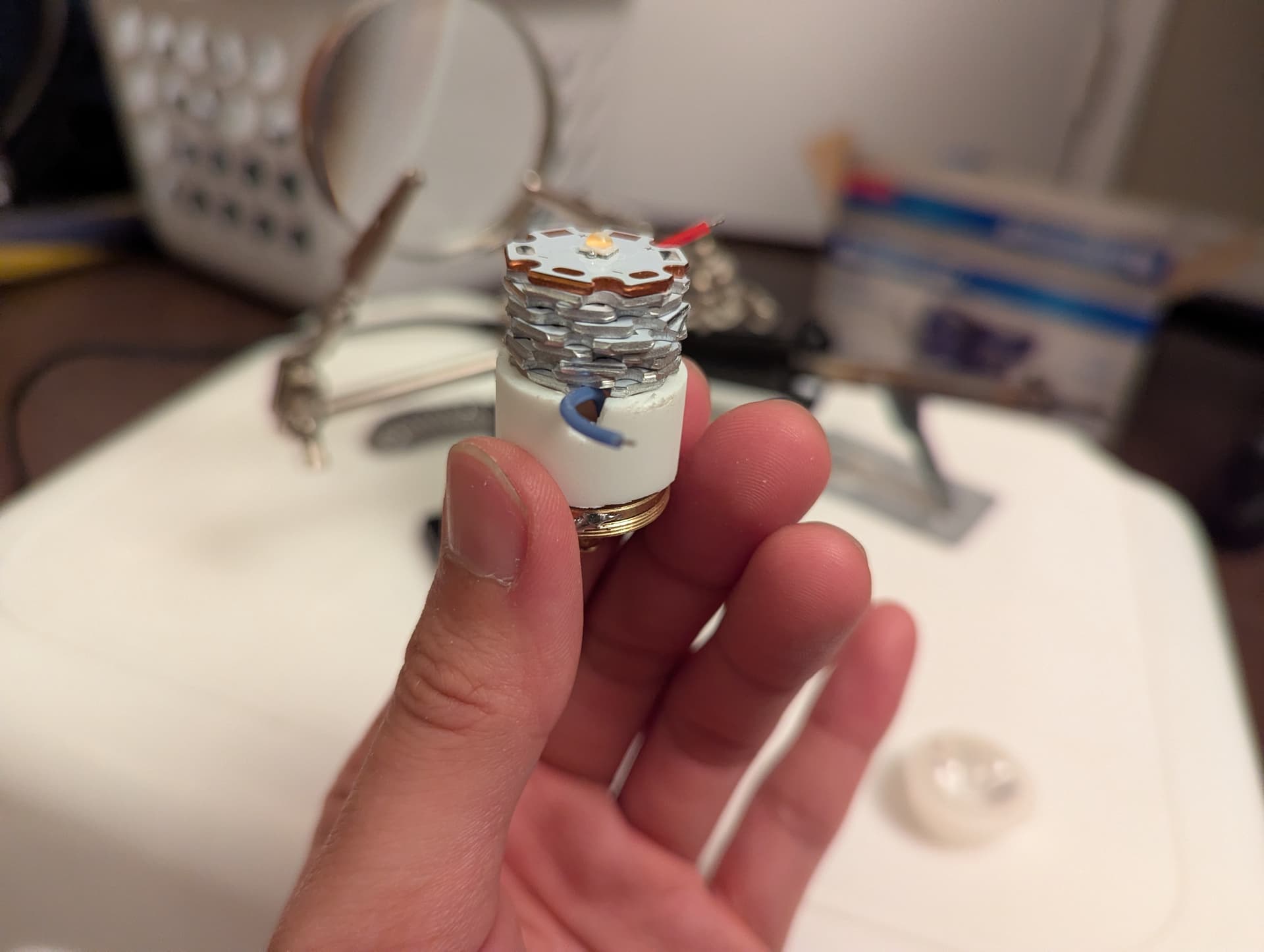
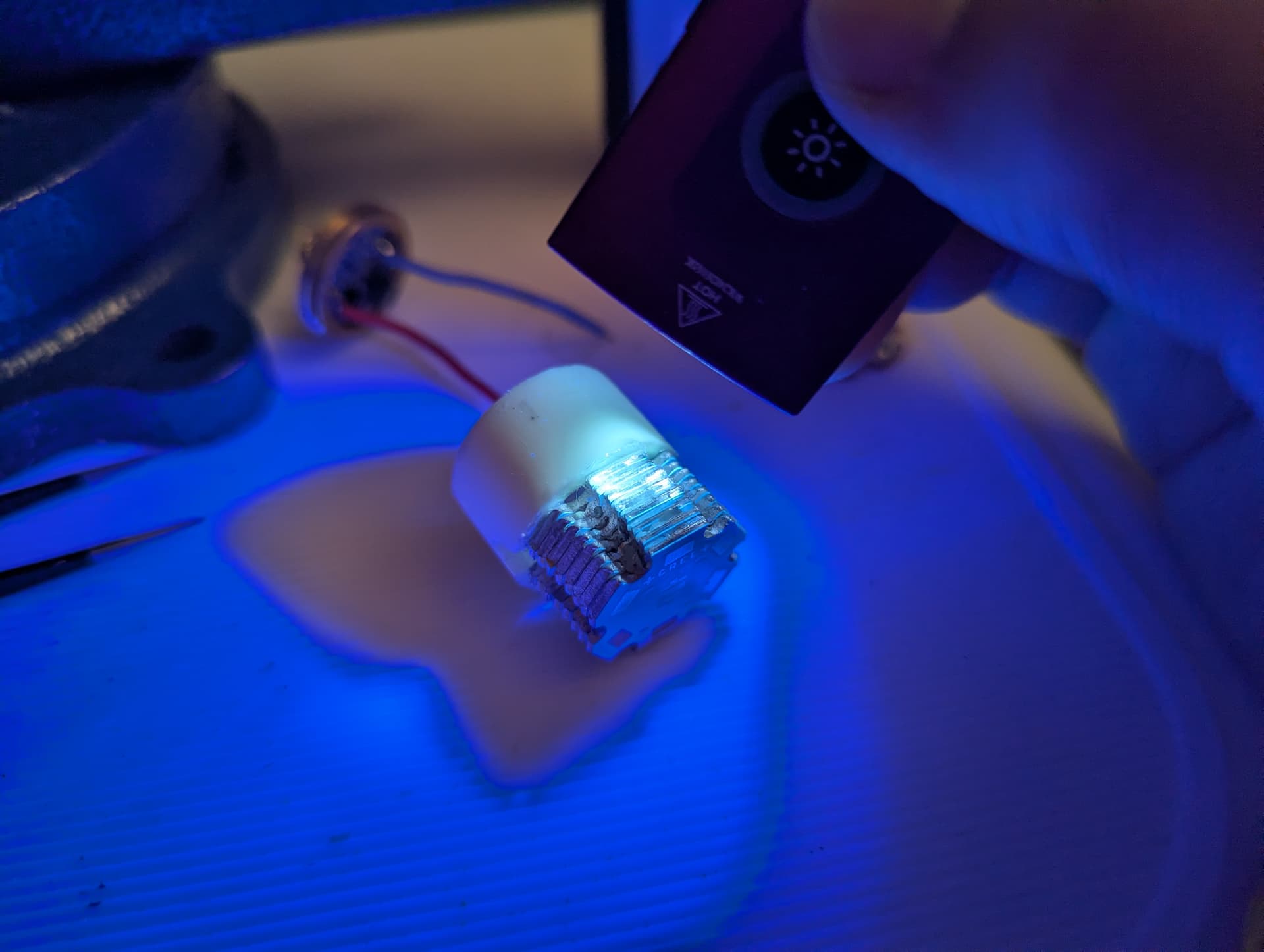
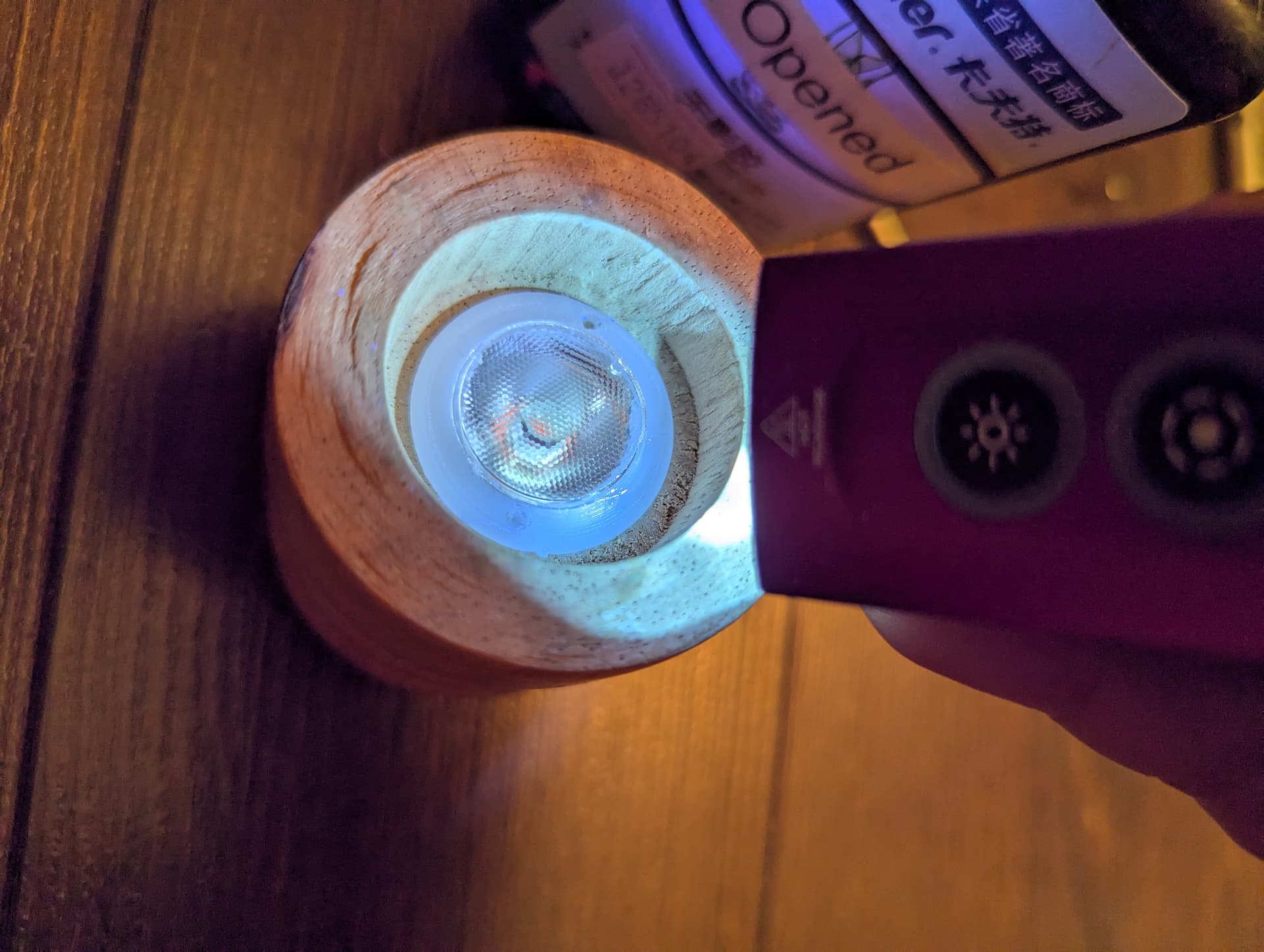
I stacked a bunch of cheap PCBs to serve as a heat sink, but was faced with a problem: how would I fill the gap between the driver and my ramshackle heat sink? As has become the pattern now, PEX came to the rescue:
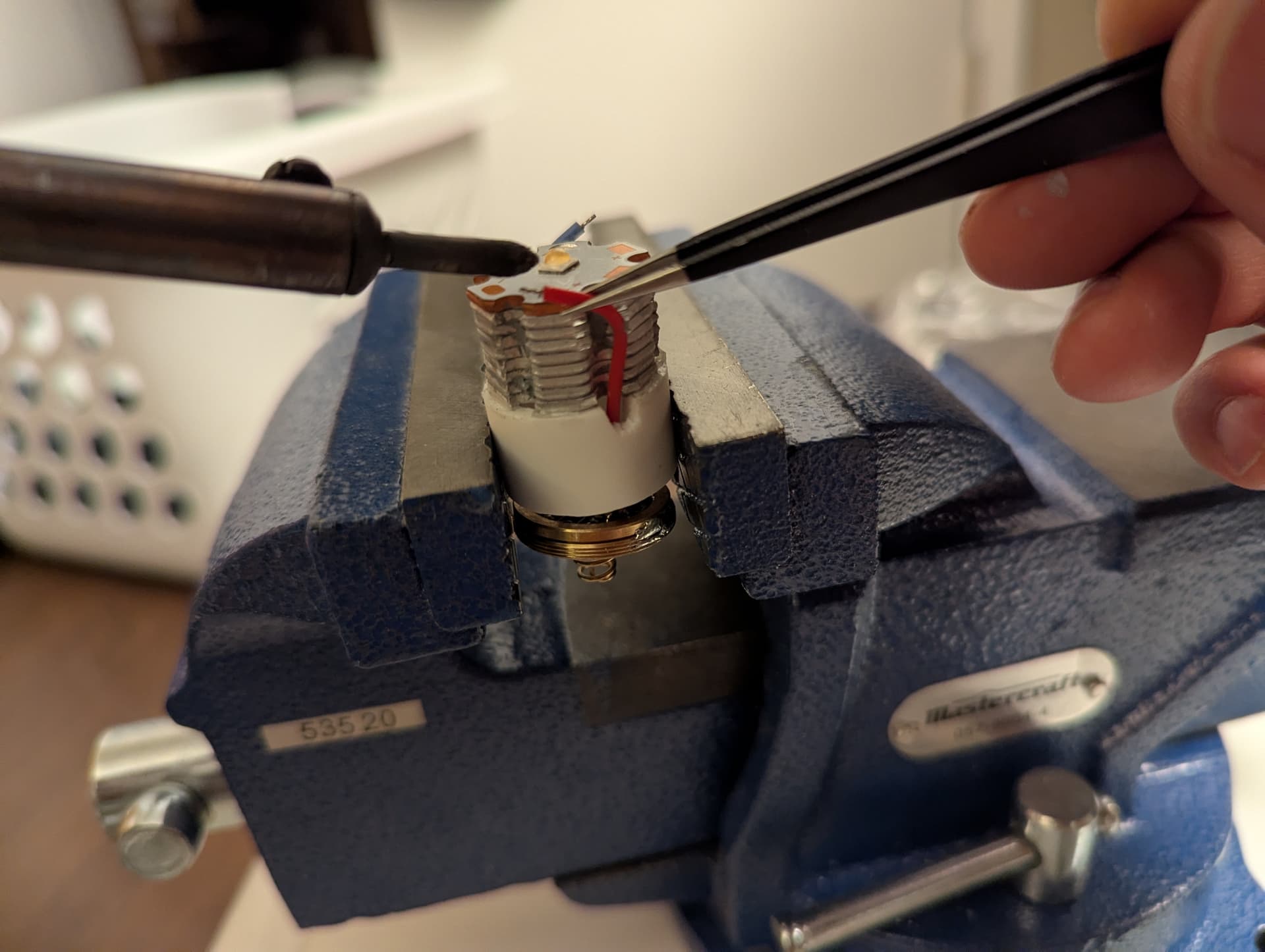
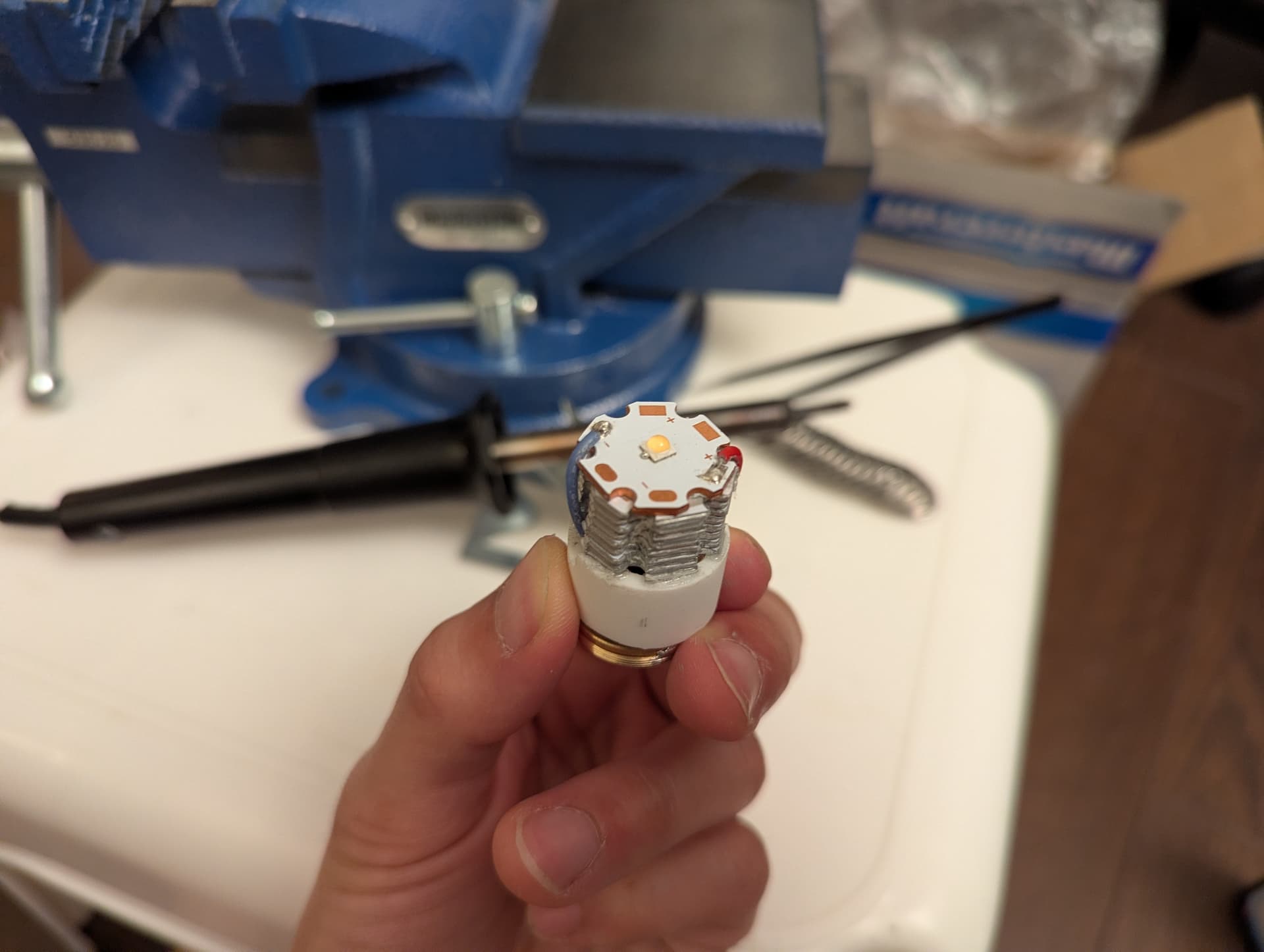
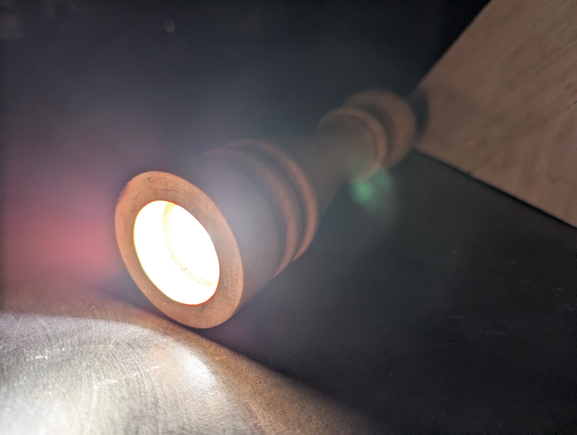
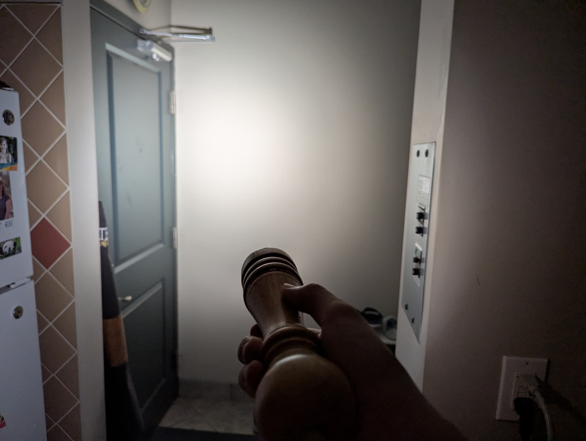
And with everything glued and soldered together, this is looking a lot more like the guts of a flashlight!
I’ll leave things here for today. Not many more steps left before I have a functional flashlight!