This is a tangential continuation of a discussion from this thread.
To set notation, consider a circular Lambertian emitting surface inside a conventional reflector. Let
r denote the radius of the emitting surface
R denote the radius of the reflector’s opening
h denote the height of the reflector
p the proportion of light captured by the reflector
S denote the ratio R/h, interpreted as “shallowness”.
Furthermore, it is known that the light’s concentration can be measured by the candela per lumen, i.e., cd/lm ratio. Let
c = sqrt(π cd/lm) denote the “beam acuity index” introduced by @mcjtom. I propose renaming it more descriptively as the “linear concentration index”, or as Proposition 2 suggests, “linear magnification factor”.
To derive a formula for the hotspot, it is necessary to define what the hotspot is. From my observation:
the hotspot is the region in space where an observer can see the entire rim of the reflector lit by the image of the emitter.
By circular symmetry, it is not too difficult to see that the hotspot takes the shape of a circular cone; thus, it is sensible to compute its apex angle. For consistency, I will let
θ denote the radial apex angle of this cone, in radians.
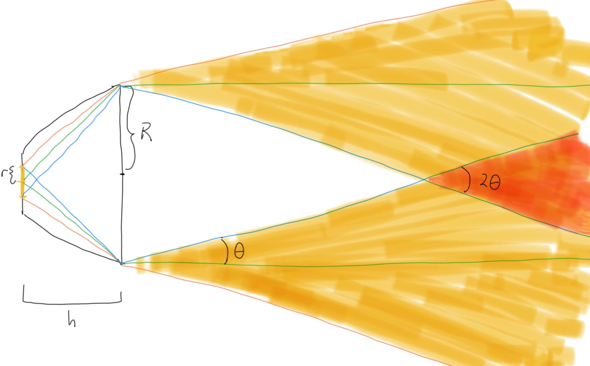
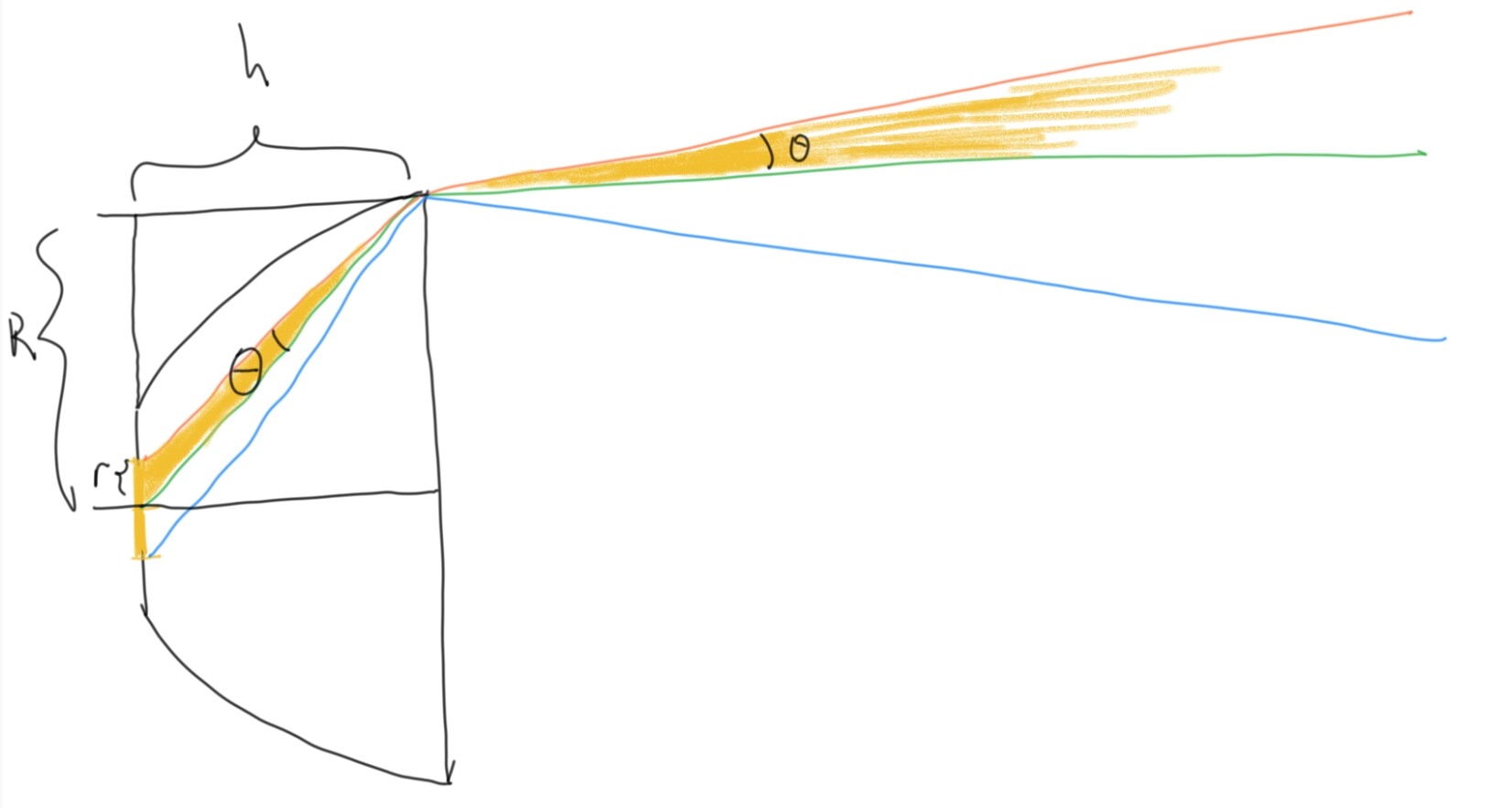
Below is an illustration of the relevant quantities; the angles are not drawn to scale for visual clarity.
The colored lines are paths taken by photons. In the top yellow region, an observer sees the top rim of the reflector lit up by the image of the LED. In the bottom yellow region, an observer sees the bottom rim lit by the LED. Their orange intersection is the hotspot.
The proposed formula: θ ~ (r/h)/(1+(R/h)^2) ≈ S/(1+S^2) 1/c = sqrt(p(1-p)) 1/c.
To get the diametrical angle in degrees, multiply by 360/π ≈ 114.6.
Here, “~” denotes asymptotic equality, and “≈” denotes a weaker notion: equality up to a small constant multiplicative error.
A brief sketch of the derivation below.
Observation 1: the green-orange and green-blue angles are approximately equal. Furthermore, each angle is unchanged by reflection.
Proposition 1: θ ~ (r/h)/(1+(R/h)^2) for small r/h. This follows from approximating a difference of arctangents via its derivative.
Proposition 2: c ≈ R/r. This follows from observing that a bare emitter has 1/π cd/lm, which increases by a factor of (R/r)^2 upon magnification by the reflector. For simplicity, we assume no losses from the reflector’s truncation at the latus rectum.
Proposition 3: p = 1/(1+S^2). This follows from looking at the sphere of constant intensity in front of the Lambertian emitter, computing the area of its spherical cap, and simplifying some trigonometry.
At this point, the first part of the formula is already given by Proposition 1. The second part follows by substituting in Proposition 2. The third part follows by substituting in Proposition 3.
Need more time to absorb it, but spotted one aspect that is common in both methods: the proportion of light reflected into the beam (your p).
The way I’ve done it was integrating Lambertian intensity (not constant) over the solid angle corresponding to spill and subtracting this fraction from 1 to get the beam fraction.
It seems to work nicely as a function of spill half (flat) angle: p = 1 - sin²(alpha) = cos²(alpha). Then to get rid of alpha I used h/D (the inverse of your S) and arctan and ended up with a royal mess. Just as I was about to drop the project I found these obscure trigonometric identities that saved the day:
sin(atan(k)) = k/√(1+k²)
cos(atan(k)) = 1/√(1+k²)
So according to me the fraction of total output in the beam is
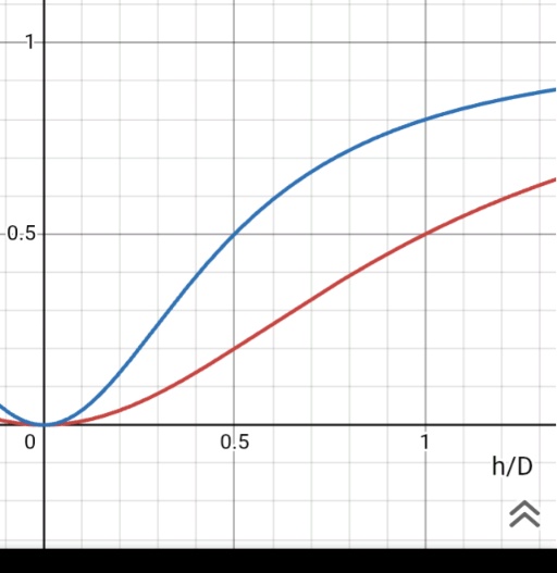
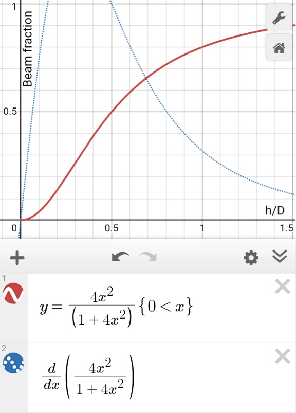
p = 4(h/D)²/(1+4(h/D)²)
I wondered how that compares to your calculation and used h/D = 1/S in the plot below (yours is red, mine is blue, x is h/D, y is the beam fraction)
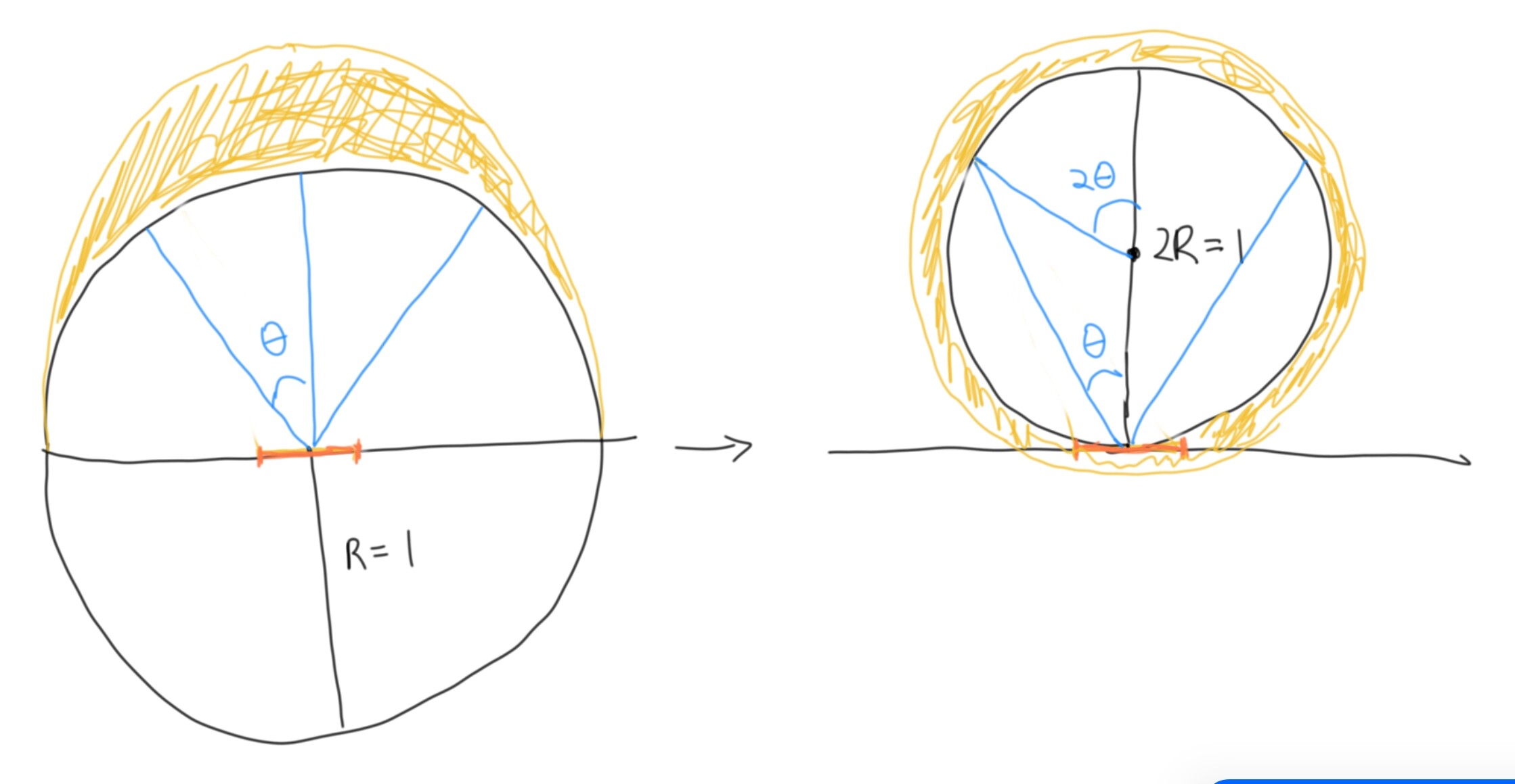
I followed everything you did up to and including this point–yes, the obscure identities also saved my day! I avoided integration by looking at a sphere in front of the emitter (rather than centered at the emitter), on which intensity is constant, and the spill angle doubled.
I defined S = R/h = D/(2h) as I found working with the radius a bit easier, so I think we should have h/D = 1/(2S) and get the exact same plot.
Pictured as black circles are two spherical surfaces one can try to integrate over, the latter in front of the emitter and having half the radius of the former. Blue is the spill cone, and the filled-in yellow represents intensity on the surface. Orange is representation of the Lambertian source.
BTW, I was playing with Enderman’s reflector calculator here and noticed something wonky with the standard reflector model.
I tried to model a C8 with SFT25R, which has emitter diameter d=1.7mm, reflector aperture c=40mm, focal length around f=2.78mm, center hole diameter v=4f (always holds for standard parabolic reflectors) = 11.12mm. The calculator gave me a beam half-angle of around 8.7 degrees, which is a full divergence angle of 17.4 degrees, which can’t be right! Could you put the numbers in and double-check me?
My formula, on the other hand, predicts a full divergence angle of 2.2 degrees. I tried measuring my C8 SFT25R (with a known reflector deformity that makes the hotspot hard to define), and got a hotspot diameter of 0.3-0.4m at 8m, which suggests a divergence angle of 2.1-2.9 degrees.
For C8 the 85/Acuity = ~4 degrees full divergence (taken straight from the Map and assuming h/D is not far from 1). That predicts more than half meter spot on your wall. May be an overestimate, but it’s just one light.
What’s the h/D for C8?
The 85/Acuity formula doesn’t use h/D to compute the fraction of light going to the beam - it assumes that h/D is not that different from 1 for relatively throwy lights and that ~80% of light goes to the beam and the rest to spill (then fudges it with the Gaussian truncated at FWHM). I don’t expect it to be too accurate, but the practical advantage is that it needs just one parameter - the Acuity Index.
If there is a set of actual beam divergence angle measurements for lights with well-measured Acuity, this 85 factor can be calibrated. The good news is that in both methods the final formula is in the k/Acuity format, which gives me hope.
There are conflicting sources on the dimensions of the reflector, and Convoy’s own numbers are surely incorrect. I’m confident about 40mm diameter, and am currently taking 33mm for height. So h/D=0.825.
I’m actually pretty curious where the h/D ratio falls for most lights. For throwers with very deep reflectors (like Convoy S6) 1 seems a good estimate, but I get the feeling that most lights would fall around 0.75-0.85. Fortunately we do not need extreme accuracy, given the fuzziness of the hotspot boundary. It would be nice to omit one parameter, but it remains to be seen how much variance there is in reflector aspect ratio, and how much it affects the calculation.
I wish! Measuring the hotspot angle carefully is a very complicated task, given the fuzzy boundary, and the fact that throwers require very long distances. The best one can do is give an interval estimate. The fact that all of the formulas for angle depend reciprocally on sqrt(cd/lm) is not too surprising, since it was created with the intention of capturing one-dimensional changes.
As I stated in the other thread, different LEDs in any given light is or at least has the potential to change the size of the hotspot.
At least at a 25 ft distance I’m seeing different sizes with the S2+. I will confirm this with longer distances in the near future.
I measured 2 lights from a distance of 25 ft.
Lumintop GT Mini had a hotspot of 16 inches and AI calculated the angle at 3°.
Convoy S6 with a sft40 I had a hotspot of 3 ft and AI calculated the angle at 6.87°.
This is not trying to get into bezel diameters or depths of reflectors. This would be just from a single point.
The question I posed to AI was:
With a spread of 3 ft at a distance of 25 ft what would the angle be?
This was Google Gemini.
It explained all the math and gave me an answer.
Yes. Though the changes in the beam fraction due to variations of h/D (in the zone of practical interest) are dampened a bit by the slope being pretty low, I think.
If you know reliable values for max lumens and max candelas (or ANSI meters) for the flashlights whose hotspots you just measured, you may want to enter them on the Map of Flashlights, and we can figure out how well our beam divergence predictions match your values.
This is very valuable data! First, I can confirm that the AI is actually right this time: 16in @ 25ft is 3.06 degrees, and 3ft @ 25ft is 6.87 degrees.
We know a good deal about these lights: first, they use emitters with around 4mm^2 LES, which gives an “effective” emitter radius of 1.13mm (a circle of equal area). The GT mini’s reflector has 43mm diameter and 40mm depth, and the S6’s reflector looks around 19mm diameter and 19mm height.
Plugging in these numbers, my formula predicts 2.51 degrees for the GT mini, and 5.45 degrees for the S6, both on the low side. Part of this could be due to the square shape of the emitter causing the hotspot to have an ill-defined boundary.
If I took the radius to be the smallest circumscribing circle around the emitter, i.e., 1.41mm, I would instead get 3.13 and 6.80 degrees, which is pretty good compared to 3.06 and 6.87. For square emitters, maybe circumscribing radius is better than “effective” radius as a predictor for beam behavior.
Thanks for the sanity check! The 1/c term later appears via the substitution c ≈ R/r, so the dependence on 1/c is still there, just less visible! This approximation also justifies interpretation of c as the “linear magnification factor”: an observer at the receiving end of the beam sees the image of the LED dilated by this factor.
I took a look at the coefficient S/(1+S^2) for S = R/h = D/(2h). In the range D/h = 2 to D/h = 2/3, we have S = 1 to S = 1/3, which causes S/(1+S^2) to vary between 0.5 and 0.3. So it looks like the variation in D/h is still significant. The derivative alone doesn’t tell us about proportional change.
Even with relative changes in h/D the function seems inelastic. For the almost all-inclusive range of h/D from 0.5 to 1.5, the elasticity varies from 1 to 0.2, I believe. For instance, at around h/D=1 a 10% change in h/D should result in some 4% change in the fraction of light feeding the beam.
Sorry for the change in notation–the variable correspondences are right.
I derived these two formulas with different model assumptions. The former assumes that (1) everything that doesn’t end up in spill is in the hotspot, and that (2) the hotspot achieves maximum intensity everywhere. The latter uses a definition of hotspot that does not assume (1) or (2).
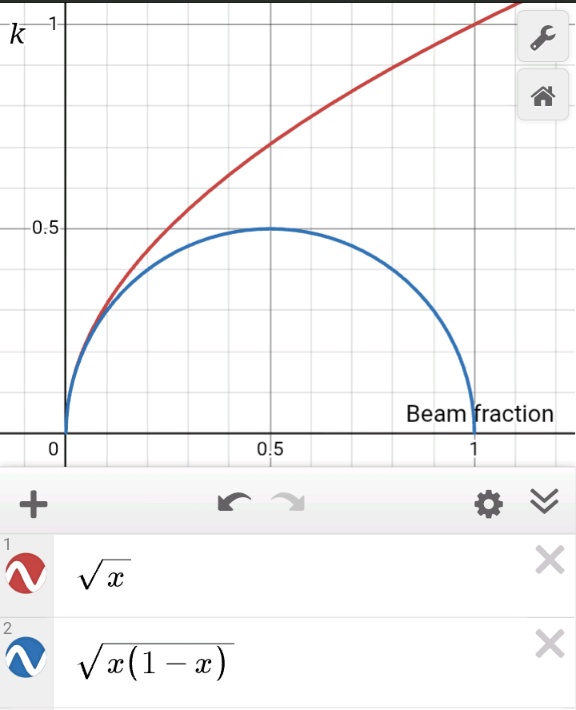
With a small enough error range in h/D, the low elasticity is ok, but having h/D go from 1/2 to 3/2 is too much. Also, the quantity determining the divergence angle is sqrt(p(1-p)), which descends sharply with p close to 1.
Could you elaborate some more - I still don’t get it.
I’m interested more in how to interpret it rather than how if follows from reflector geometry derivation.
The way I see it is that we hope that beam angle is in the form k/Acuity. Whether k can be safely a constant, a set of constants, or a function of something else (like h/D or less conveniently fraction of light in the beam) is a question.
I have a feeling that it may not work too well for things like LEPs or Z1 with almost all the light feeding the beam, but please explain.
p.s. Also I want to make sure that θ in your formula represents full divergence angle of the beam, not the half-angle. The sketch above it suggest half-angle.
Radial apex angle = half-angle = half-divergence-angle = ½ full apex angle = half-vertex angle = semi vertical angle = half vertical angle, and I’m sure there are more.
It’s a miracle that our semi-independent results look half-close
I propose to standardize on ‘full beam angle’ or simply ‘beam angle’ and (full) ‘spill angle’ and leave half angles for internal calculations.
I believe you understand 1), but 2), I’m assuming means a hotspot with uniform intensity, and either: pure hotspot, or distinct hotspot.
I also assume that the equation accounts for a hotspot with varying degrees of intensity throughout the hotspot, therefore conditions 1 and 2 do not apply.
The way I derived it doesn’t assume any of the two either. At this point I think we both agree that if one wants to estimate full beam angle from the Acuity Index (Y axis on the Map), it should take a form of:
Full_beam_angle ≈ k/Acuity_Index
What we’re not that sure about is what this ‘k’ should be. We probably agree that k can be either:
some constant, or
maybe a set of constants, each fitting some category of lights, or
a function of something else, like the reflector’s height to its bezel diameter ratio or the fraction of lumens in the spill or beam.
If it’s a constant, all you need to know to estimate the full beam angle is the Acuity Index which you can read off the Map.
@QReciprocity42 thinks that a constant may be too crude to be practical and that k needs to be adjusted for each flashlight depending on its individual reflector’s height to diameter ratio (that you need to know and can’t read off the Map).
Using a reasonable function instead of a constant could well be necessary (the bummer is that now you would also need to know h/D or f_beam). I’m confused as to what the shape of his proposed function for ‘k’ would do to the full beam angle estimates.