There is no holder.
The battery is in the parts list in the first post:
Seiko MS412FE-FL26E
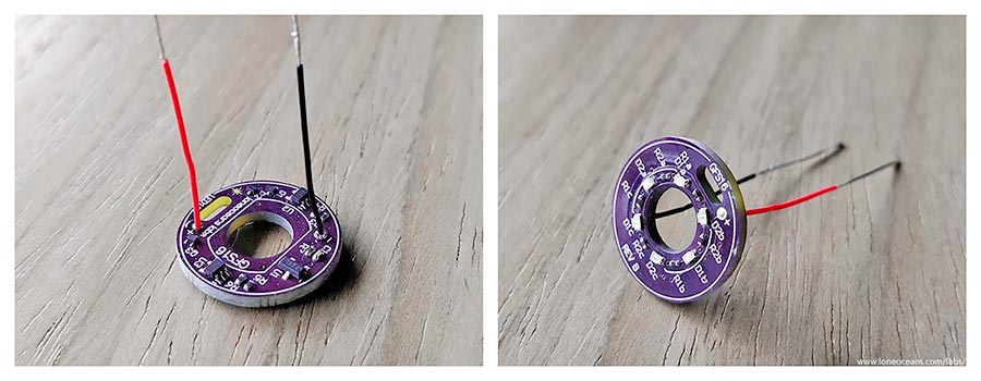
Correct, the battery tabs just get soldered to pcb pads.
I tried everything with the FET switches including Lexel recommendation, the battery just dies in under 2 weeks.
a solution would be the rechargeable version and a diode on the board, so the coin cell gets charged by the main battery if the voltage gets lower
https://www.mouser.de/ProductDetail/Seiko-Instruments-Micro-Energy/MS412FE-FL26E
Mouser and others dont ship those batteries outside USA
You can get them on Ebay from China as I did.
Fady, you're right, you can change the resistor values to change the threshold voltages. Fady, are you also still having problems with the battery? It's fairly different to solder such a small package and you need to be very careful since too much heat can damage the cell. I've been using my lighted FET tailswitch in my main light for the past half year bringing it on many outdoor camping trips and it's been still working great.
Lexel, yes the MAX9052 is definitely suboptimal in quiescent current consumption of ~55uA typical. LEDs should draw on the order of ~200uA for 3 LEDs, so the comparator definitely is a large power hog. For your voltage regulator, you can use a better one I think, since there exists a lot of sub 1uA LDOs, and yes you can then use a much more jellybean comparator.
Thanks everyone for the support! When I have time I'll maybe do a quick update on the design.
welcome back loneoceans!!, I still have plenty of parts… ill attempt to build again and be careful when soldering the cell, on the other hand Lexel came up with an improved design based on your LED board, he added a LDO regulator to have a constant voltage drop across the bleeder thru the entire battery voltage range… so led current is constant therefore voltage sensing can be easily calculated. check it out here.
Sounds good, well the main idea was to keep this board as simple as possible! I think the LDO is more for a constant LED brightness. The voltage sense inaccuracy isn't so much of a big deal if the bypass resistor is small <=1kR, and the voltage divider is large (and everything else is within spec).

Anyway it's true that the quiescent current for my Rev A one is a little large (>50uA), which is a large % of the LED current draw (~200uA for 3 LEDs but depends on brightness), so over lunch I did a little revision replacing the comparator with an ultra low I_q one, and added another ultra low I_q voltage reference. I don't mind the LED brightness changing, I suppose it's easy to add another v-reg, but I'd prefer the LED brightness giving me another estimate on battery voltage, instead of just losing this information in the Vreg as heat. LED side remains the same..
Total I_q is an order of magnitude less and now closer to 5uA + LED draw. More details soon when I have time!
Cool!! Hope you release this on ashpark soon, correct, the LDO is for constant led brightness but it also allowed the use of a larger value bleeder without effecting the accuracy of the voltage reading since the compactor Vref was driven off the LDO divider circuit which also remained constant… on your Rev A board… increasing the bleeder value to 1K increased the hysteriss by a lot and really messed up the accuracy but I’m glad you updating this design!!!
Awesome, I can’t wait to see what you’ve come up with! Please include a BOM when you write about it (I’m mostly curious about what v ref you’re using and how it’s wired)
More to come soon and I'll update the front page, but here's a link to the OSHpark PCB design.
https://oshpark.com/shared_projects/L27QGJFW
*note: this Rev B board has now been successfully tested and recommend for your own builds*
I rotated the PCB 45 deg because OSHpark tends to make snap-off cutouts on the 4 sides which can cause the part with the cut-out for the tiny battery to break. Hopefully this helps.
Total I_quiescent:
- Comparators (two) - 75nA typ x 2
- Voltage Dividers at 3V - 2 + 1.8uA (I suppose this could be even lower)
- Voltage Reference at 3V - 1.5uA
Total: ~5.5uA
Previous I_quiescent = ~70uA, so this should be a >12x improvement in standby time after the LEDs turn off, and a good 30% or more in regular standby time with LEDs on.
Components:
- R1a,R1b,R1c - 30kR 0402
- R2a,R2b,R2c - 12kR 0402
- Q1 - RZM002P02 or any other SOT723 P-Fet
- Q2,Q3 - NTK3043NT1G or any other SOT723 N-Fet
- D1a,D1b,D1c - Blue 0603 LED 150060BS75000 or colour of your choice
- D2a,D2b,D2c - Red 0603 LED 150060SS75000 or colour of your choice
- C1 - Any 10-100nF 0402 capacitor
- R3, R7 - 619kR 0402 resistor
note: You can also use R3 = 681kR or 750kR depending on the threshold voltage setting - R5 - 470kR 0402 resistor
- R4,R6 - 1M 0402 resistor
- U1 - MAX6007BEUR+T
- U2,U3 - TLV3691IDCKR
Features:
- Low I_q for longer standby
- Simple
- 3.32V low voltage threshold (R3 and R4, sensed with R4 as lower), depends a little on your driver bleeder resistor.
- 3.01V turn-off threshold (R5 and R6, sensed with R6 as lower)
- Careful component placement so no components hit the shelf on the LED side
- Works well with GFS16 system
More to come soon!
I had some time to put together the Rev B of the GFS16 LED Taillight board.
Here's how it looks like. The OSHpark boards turned out great, especially with the 45deg. rotation to avoid a chance of the oval-cutout breaking.
The board seems to work just as expected, and has an actual measured current draw of (5.6+-0.1)uA at a 3V LED Turn-off threshold, exactly as expected. This is over 10x LESS current draw than my Rev A version, so I think that's not a bad thing :). As the battery voltage drops, current draw should drop further.
Made a quick video of the board in action, and here's it with a 330 ohm series resistor and a power supply. The threshold voltages are about 3.4V and 3.0V for Low and Off respectively. Note that the bigger the bypass resistor, there will be a larger possible error of the threshold voltages from the voltage divider, as well as a larger hysteresis. This was discussed in some detail in previous posts.
I've also tested this with a 560R bleeder resistor across a Convoy S2+ standard driver, with R3 = 681kR. This gives a 3.55V low-voltage threshold (hysteresis at 3.75V).
Regardless, I just wanted this board to be simple and no frills. Tested all the way down to 0V and it fixes an issue with the previous Rev A design (where if the voltage drops below ~2.5V+, we were out of spec for the comparator, so the red LED could come on again dimly). No such issues for Rev B.

OSH Park boards and parts list are available in the previous post as well as the first post.
Many thanks to all the support I've received on this forums, members who've had good success building their own despite the annoyingly small components, and feedback and suggestions for improvements! Again I understand it's not the perfect tail-light, but it does provide some simple extra features over a regular tailight board.
[Edit] - I understand the components are a little bit of a pain to solder by hand... when I have time I think I'll have a go at changing the components to be larger and easier to solder.
Enjoy!
Thanks for the update, LO!
That looks really nice! Thanks for sharing it on OSH Park too! I’m hoping to see some of your driver designs going ‘live’ as well soon! :innocent:
Thanks loneoceans, I already have the boards on hand and the components are coming in today… but I wont have time to build and test until the weekend… so ill be sure to come back and update!! Thaks again loneoceans!!!
Wow this update look quite good. Fady and others, have you built your own? I am thinking of combine this with my gxb172 build as well.
Hi loneoceans,
this is very nice project, I wanted to order couple of boards but unfortunately I usually don’t use reverse clicky switches ![]()
Can your board be used for forward clicky switch without redoing components layout?
Because forward clicky swithc is a bit larget at about 12x12mm.
There are several lighted tailcap project and all of them are for reverse clicky and non for forward clicky…
Thanks
Fady had a big problem with the first rev of these switches. The battery kept dying. Loneoceans never mentioned if he solved this problem.
Tried to build one, and finally managed after destroying the first two batteries (puffed up, I assume because shorted). This was despite using kapton on both the battery and tweezers (in case it slipped off the battery a bit like it did for the first one).
The issue is that the side of the battery is still + so you have to scoot it as far as possible away from the negative contact on the board, else you can trivially solder bridge the battery (the fate of battery #2).
Third try was sorta the charm (as in it worked), but when I broke out the milliohm meter, it never did better than 33-35mOhm (it was near 50mOhm if when I clamped to the top of the 45% IACS unbridged spring from MTN). I compared a bridged plain Omten 1288 (and not one of my better ones, either) and got 19mOhm.
And then while trying to install in a light, the negative contact ripped right clean off the PCB from the most minor pressure against the battery (it was encased in two layers of kapton, btw). I’d liked to have run a test with spring bypassed for the most fair comparison, but after 3 batteries and nothing to show for it, I was done.
If you’re using a S2+ host, you’ll need to trade your metal washer bottom plate for something thinner, or the retaining ring for the spring assembly won’t sit flush with the shell (risking a short, depending on how much of the bottom of your battery is a contact).
If you could use the through-hole legs, this would be MUCH easier to assemble and try to use — and much less likely to rip apart just trying to install it.
This is a neat idea, but the battery choice / mounting is too fragile, making it practically unusable. Pretty disappointed. ![]()
My (attempted) design change. Not yet assembled or tested, but idea was to switch out the LFPAK56 FET (so only uses the LFPAK33 FET) for a coin cell retainer that the same sized cell should fit (4.6mm). The pathway to load it has to be free(ish) of components, and I tried to keep the components out from under the switch otherwise. Comments/feedback welcome (trying not to be just a negative review, but rather a suggested direction for improvement).
https://oshpark.com/shared_projects/paPrb43Z
EDIT: Fixed error in first revision (via that was too close to the spring contact area)
very good job schizobovine! I hope to see this project work for you.
In your new pcb, does this mean the switch is sitting on top of the small battery? Will this be bad for battery?
when my gxb172 driver is finished, may try to build this tailswitch also!