28/09/2023:
As a newcomer on this forum, I was pretty excited to see such a contest on here.
Since it was announced, my mind has been bursting with ideas!
I’m still deciding on what to do exactly - I do have a rough outline in my head.
I am still torn between handmade or machine aided.
All I can say for now is: I love wood and metals.
29/09/2023:
Here is a first update and teaser of the general theme of the build.
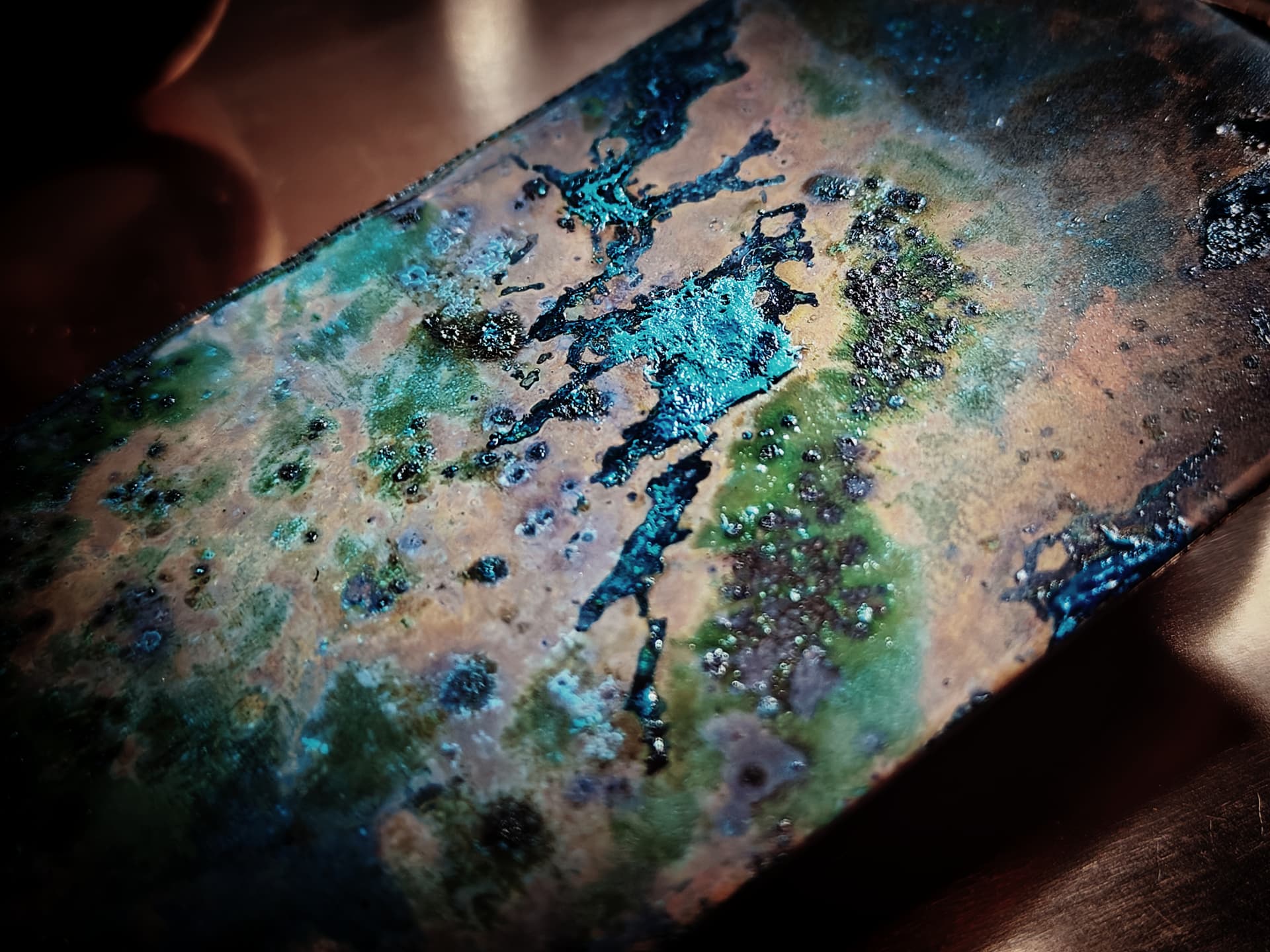
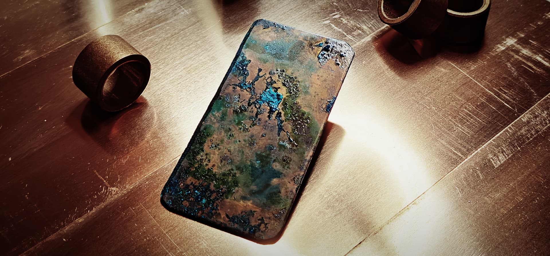
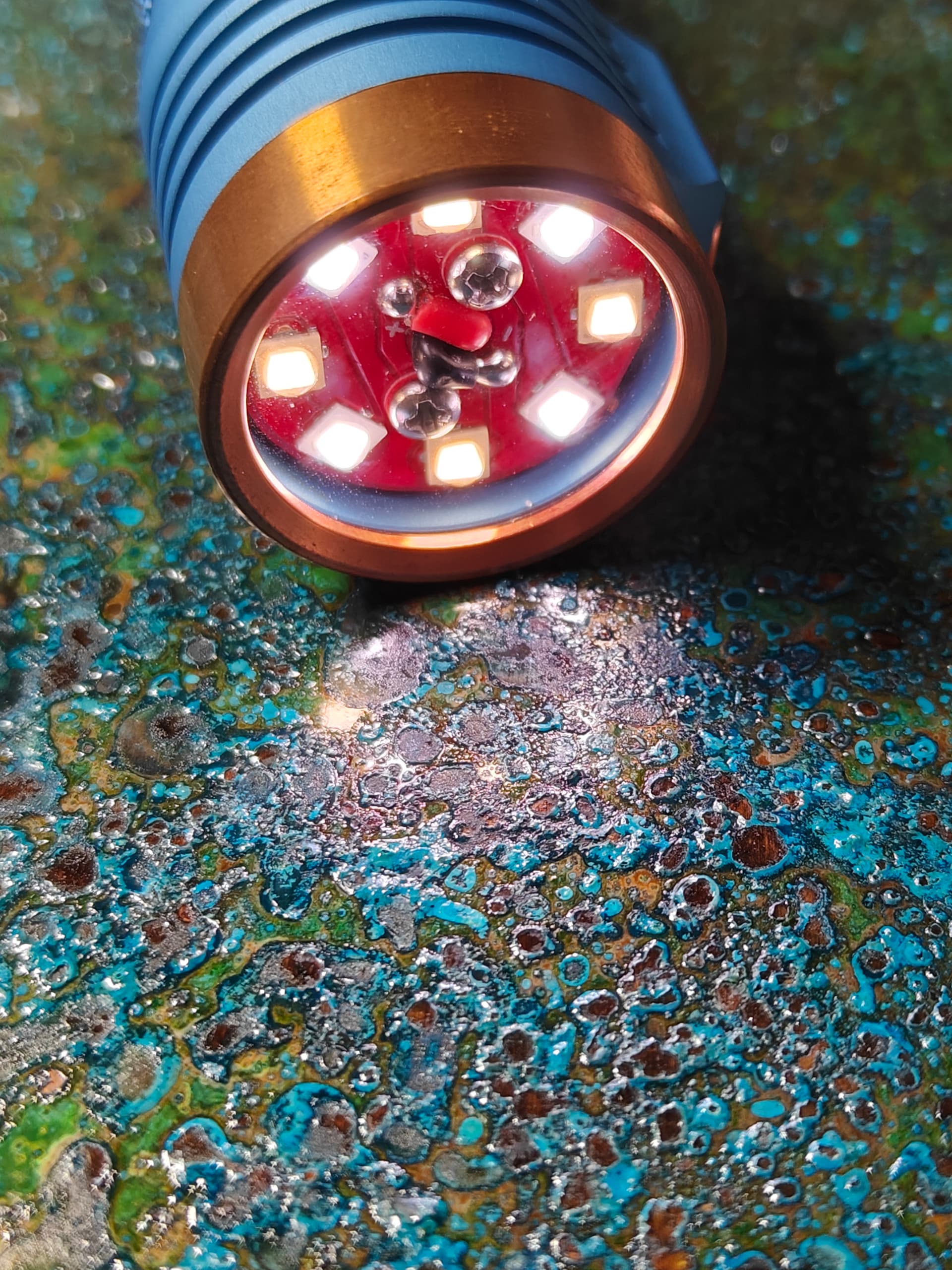
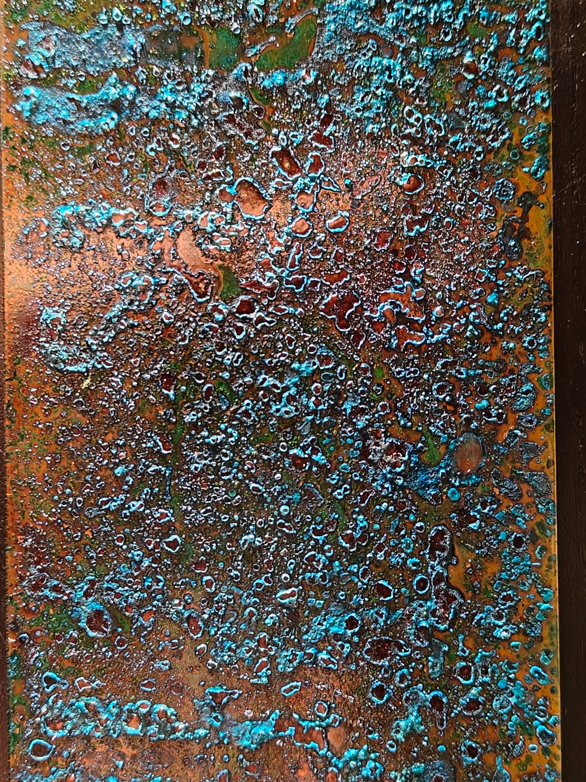
A lot of bronze, and for the first time I have tried to force a “shipwreck” patina. I’m satisfied with how the blues and greens turned out. I’ll do some more tests to get a better balance.
This is just a test piece and once I get to building, I will add a tutorial how I did it.
30/09/2023:
I start most builds out by figuring out the driver side first. The brains of the flashlight…
I am most likely recycling the 22mm 6V8A driver from the “Phobos” build(as seen here):
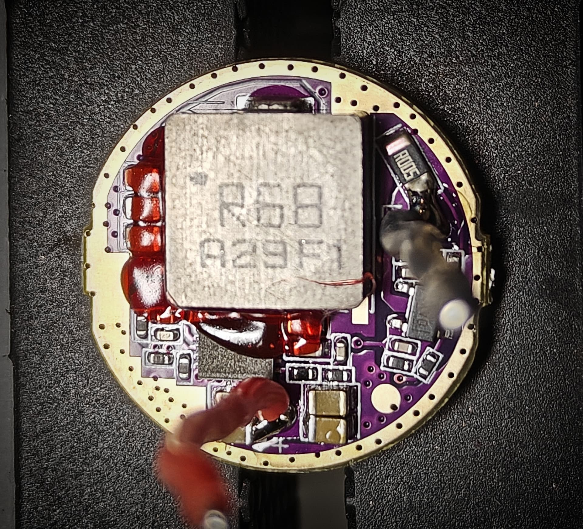
It is a hefty output at full power, so I will need to add a decent amount of heatsinking to the emitters, driver and battery. The efficiency on the lower modes is a nice bonus.
I’m leaning to Anduril as well, I’m exploring my options for 22mm Anduril drivers. But they don’t work with mechanical switches? Hmm…
Here is a small tutorial how I straighten and compress bent single strand copper wire. It is a trick I learned from making vaping coils:
Imgur link
It makes the copper extra springy, as the wire gets twisted over itself and shortens in length.
How I made the negative spring for the battery using a step drill:
A quick mockup of the driver and 18650 battery setup with lots of brass as neg/pos contact and for extra Mass for heatsinking:
Maybe I should do a 2 x 18650 parallel build?
Next up is the enclosure that needs to house this beasty setup, which will shed some light what the idea behind all of this is.
That’s it for today.
Question: should I keep doing the “Collages” or do you want the full pictures? if anyone is watching lol.
30/09/2023 (2):
For this project I was looking for the elusive high drain 20700 cells. 21700’s are just a hair too thick to fit in the brass bushings I have on hand, so I wanted to give 20700’s a try.

For those that know me from Reddit might know that I recycle all kinds of battery packs for cells.
I have this 18V Metabo pack which I can’t use anymore, and which I assumed contained 20700’s.
So let’s dissasemble it and see what’s inside:

5s2p.
Those don’t look like 20700’s though…
10 x 21700 Samsung 30T
I didn’t find what I was looking for but maybe the real treasure was the friends we gained along the way right?
People that are sending over lights to mod are def. getting a freebie ![]() .
.
01/10/2023:
So since I tore down the battery pack above and gained some new 21700’s, I have decided to switch things up a bit. While in essence still a flashlight, it will be a portable - high capacity - high CRI/output - desklight.
Included are some rough sketches.
The main elements are as follows:
- Three part design:
- main housing
- emitter housing
- flexible metal “gooseneck” connecting 1. And 2.
- Main housing:
Skeleton made out of treated wood.
- Which wood?
- Which surface treatment (burning?)
Planes will be filled with bronze 1.5mm plates*
- Force patina the bronze plates
- Cutouts for switch and USB-C
- Brass sturdy feet
Electronics:
- USER REPLACEABLE BATTERIES!
- 6 x 21700 in parallel
- Two options for charging board:
- 6A charger only
OR - 4A charger with powerbank functionality
- Driver assembly as mentioned in previous posts
- Convoy mech RGB switch embedded in bronze plate

- Emitter housing:
- 20mm x 30mm aluminium heatsink
- heatsink encapsulated in brass housing for extra mass
- Emitters still to be decided
I am leaning towards either 3V 2S2P or a single 6V 7070 (XHP70.3 or…)
- Flexible gooseneck:
- High metal quality ribbon cable (black?)
Some ideas that still need resolution:
- Incorporate Auxillary lighting in the case that accents the shipwrecked pieces
- Incorporate battery read out in a non intrusive way
- Both independent of main emitter assembly
- powerbank functionality? Seems like a must.
Any feedback or ideas are very welcome!
I’m also working on forcing the brass feet:
This is after around 6 hours in the fume chamber below, which should explain the method I used:
I’m not happy with the result, it needs to be deeper so I’ll do another 12 hours and see what happens.
02/10/2023:
So brass probably isn’t the best material to shipwreck because of the lower copper content vs bronze or copper itself.
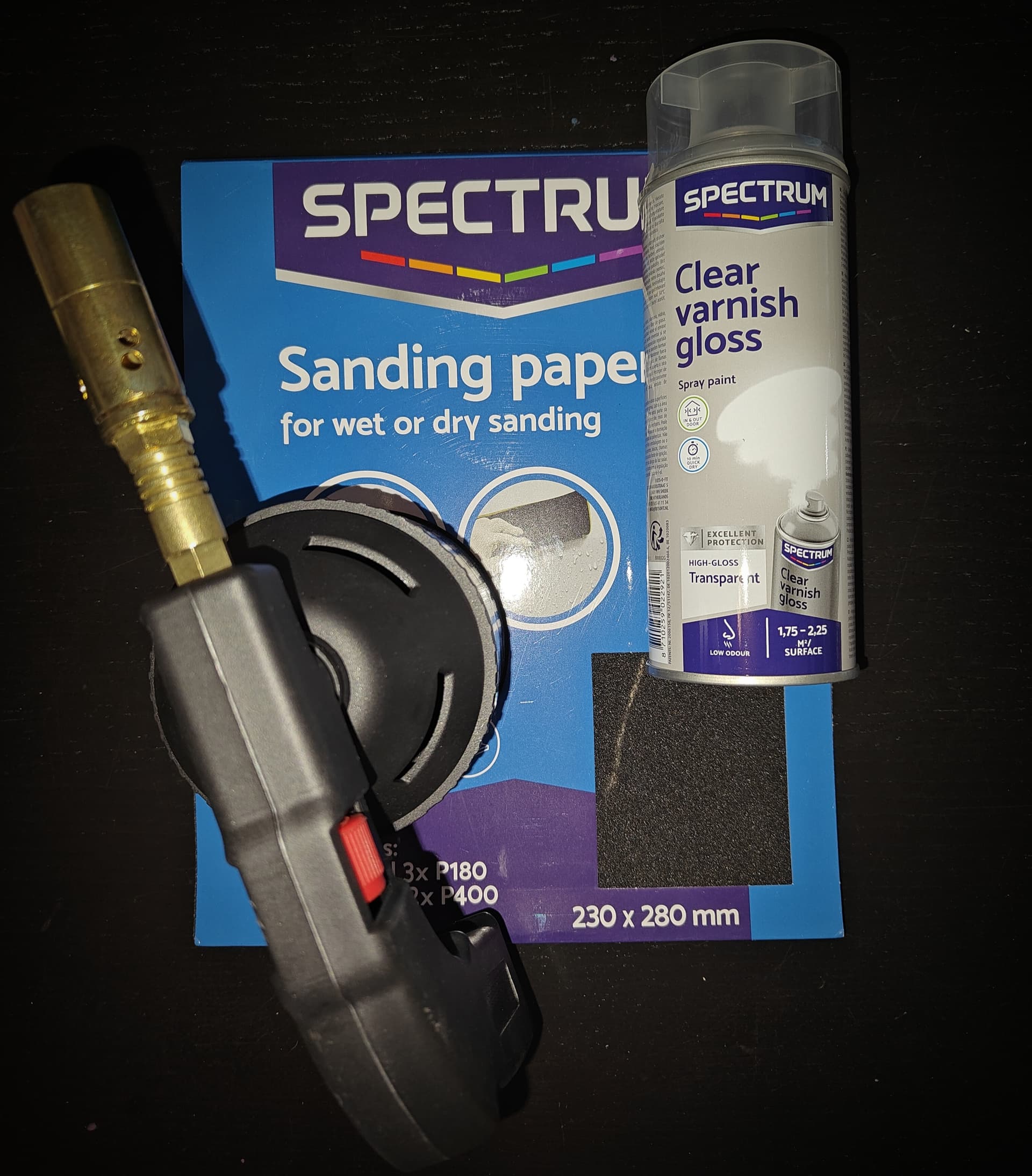
These are the finished feet after multiple coats of clear spraypaint:

And here is a comparison before and after:
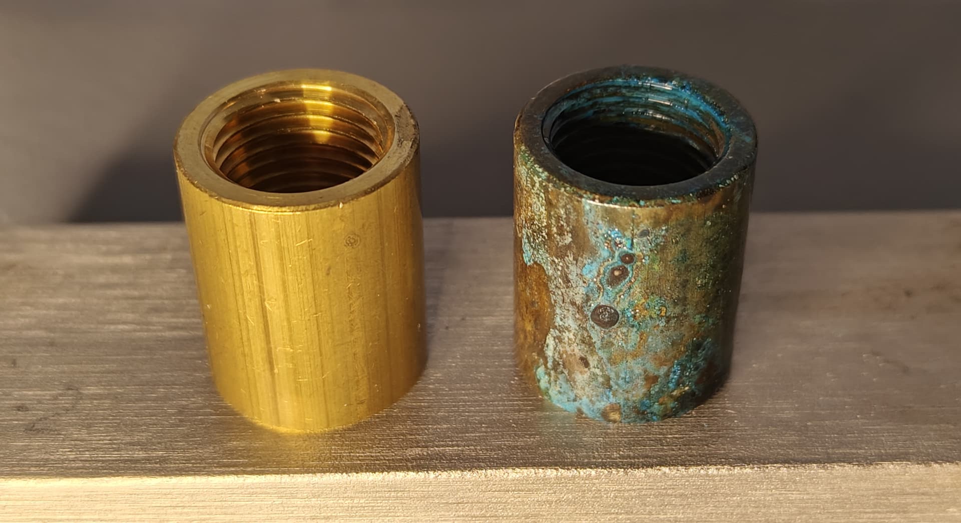
Let’s put those aside for later.
Next up: dryfitting the emitter housing.
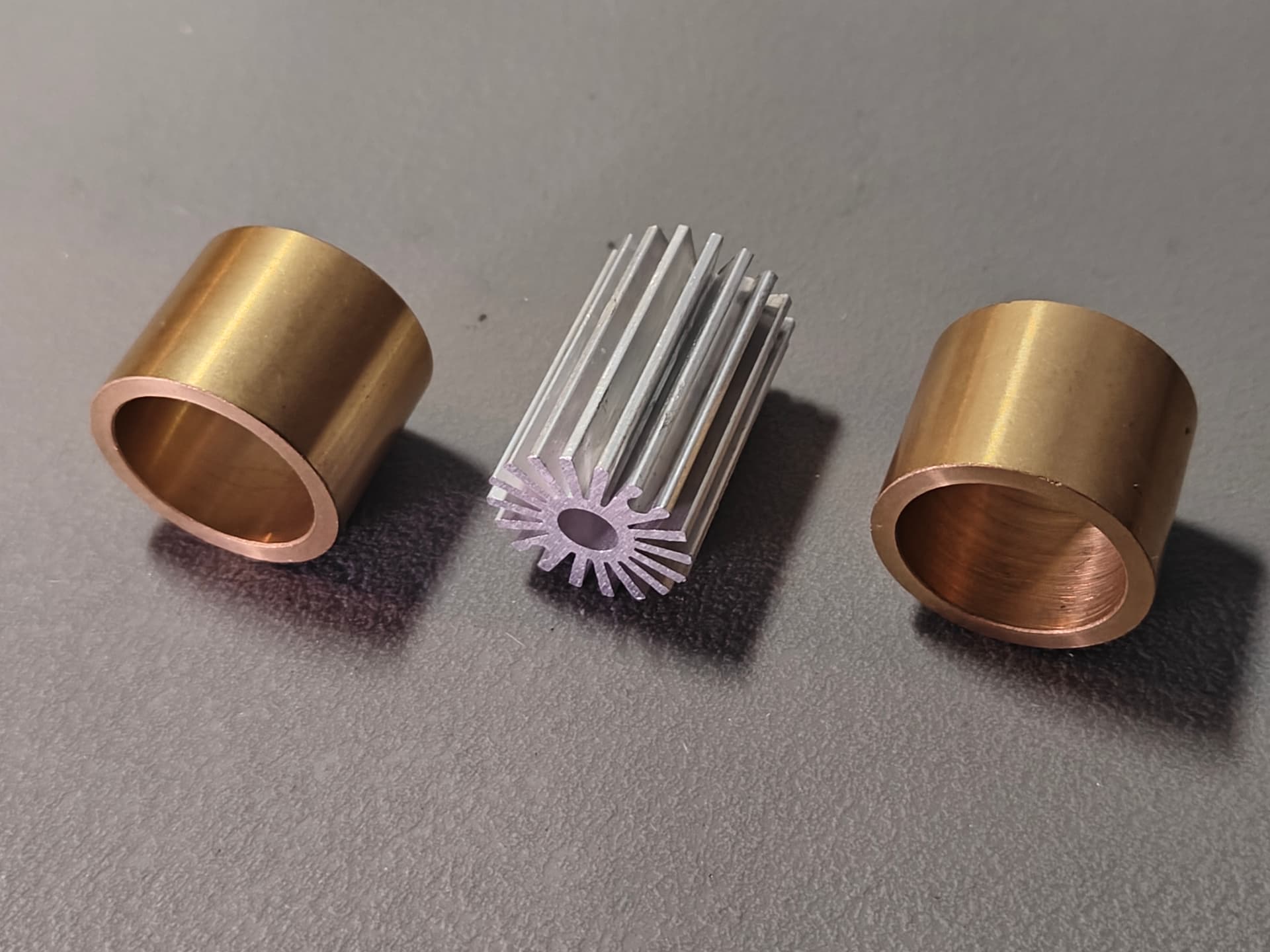
So essentially 2 brass bushings with 20.5mm ID and a 20 x 30mm aluminium heatsink. These parts fit together nicely and will be soldered together later on. The aluminium heatsink will host the emitter MCPCB. Would this be enough heatsinking?
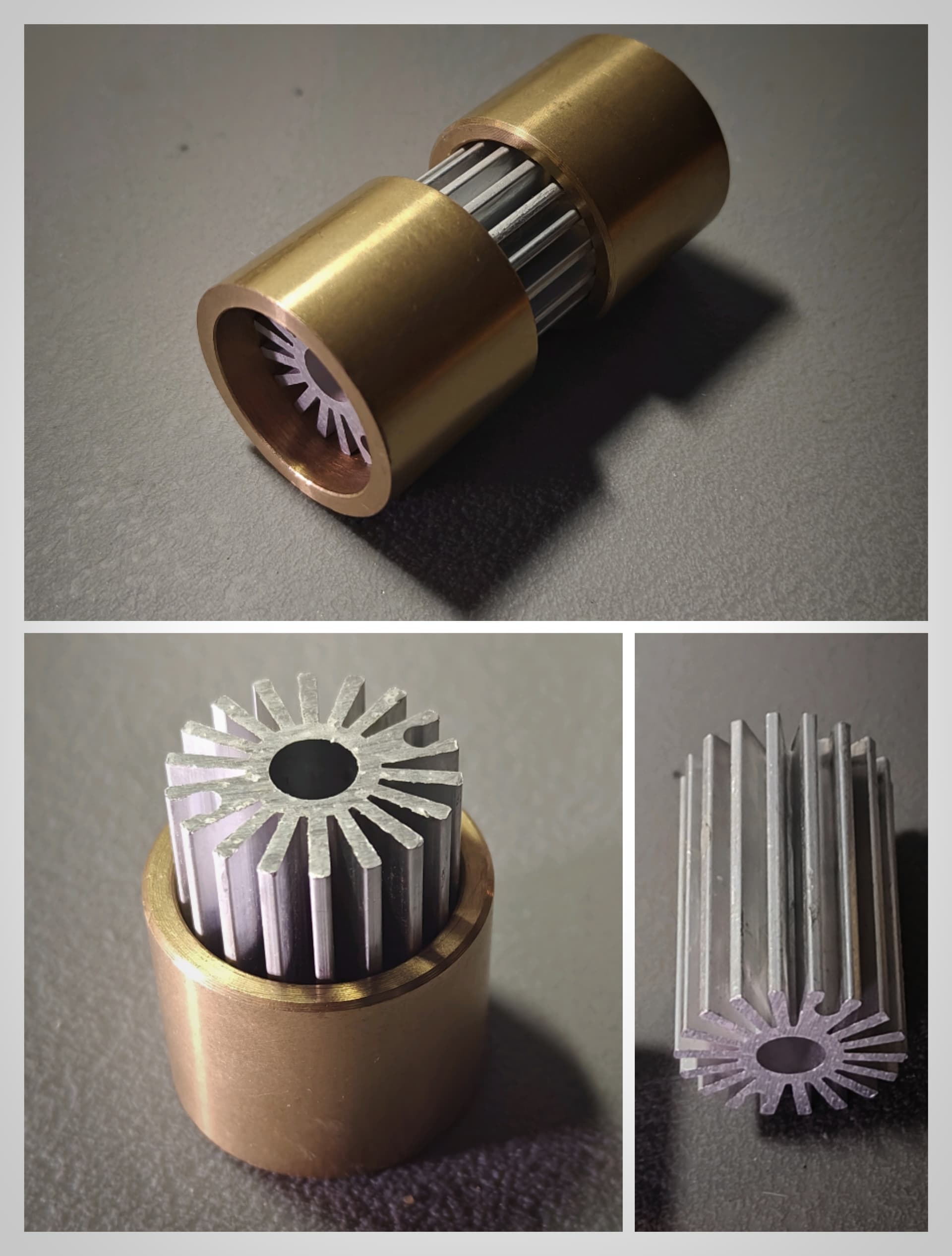
I will leave a gap between the bushing to expose some of the bare aluminium.
I’ve ordered some more parts to test, as this probably will be the most all-in build I have done.
Still have to run to the lumber mill and decide which wood I’m going to use.
03/10/2023:
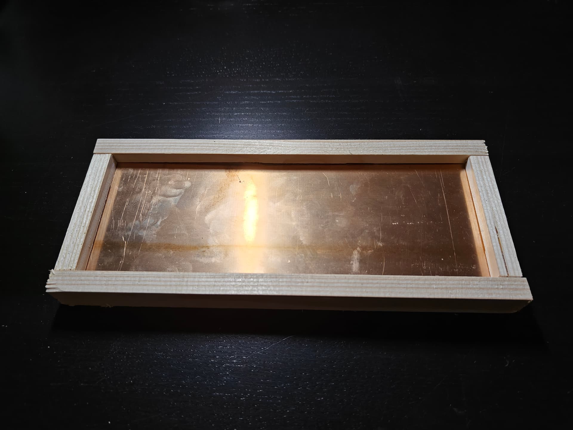
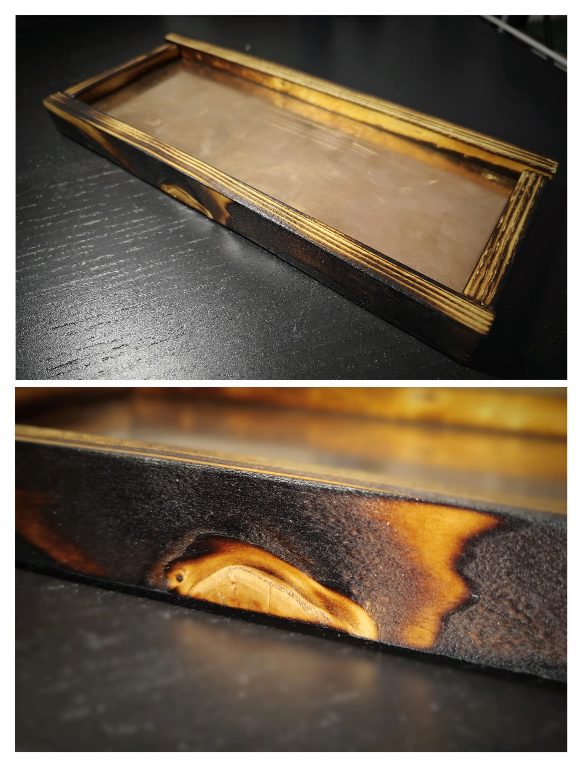
So for today I have made a prototype of the main housing. I’m rying to figure out how to connect the wood skeleton with the shipwreck bronze plates.
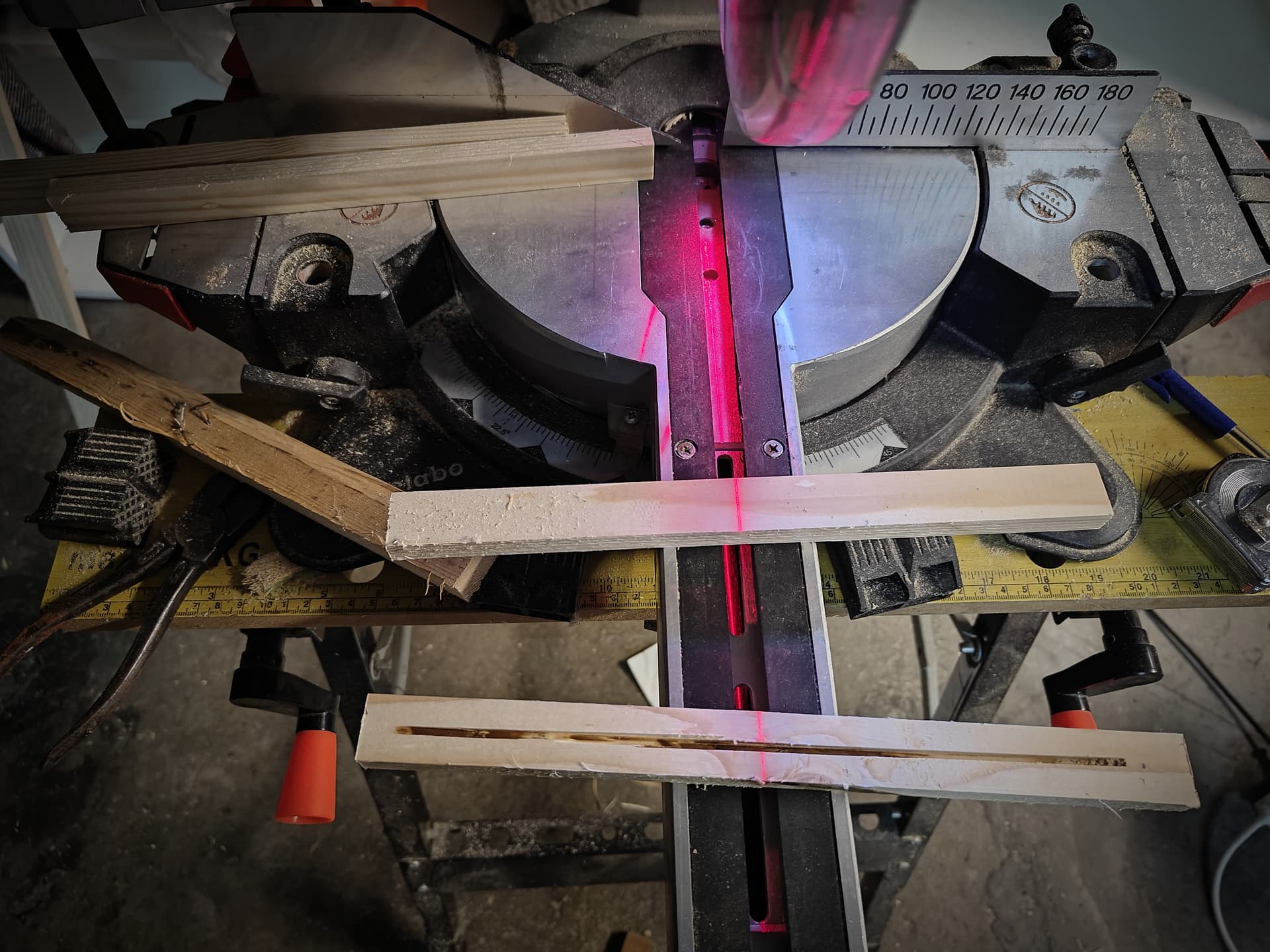
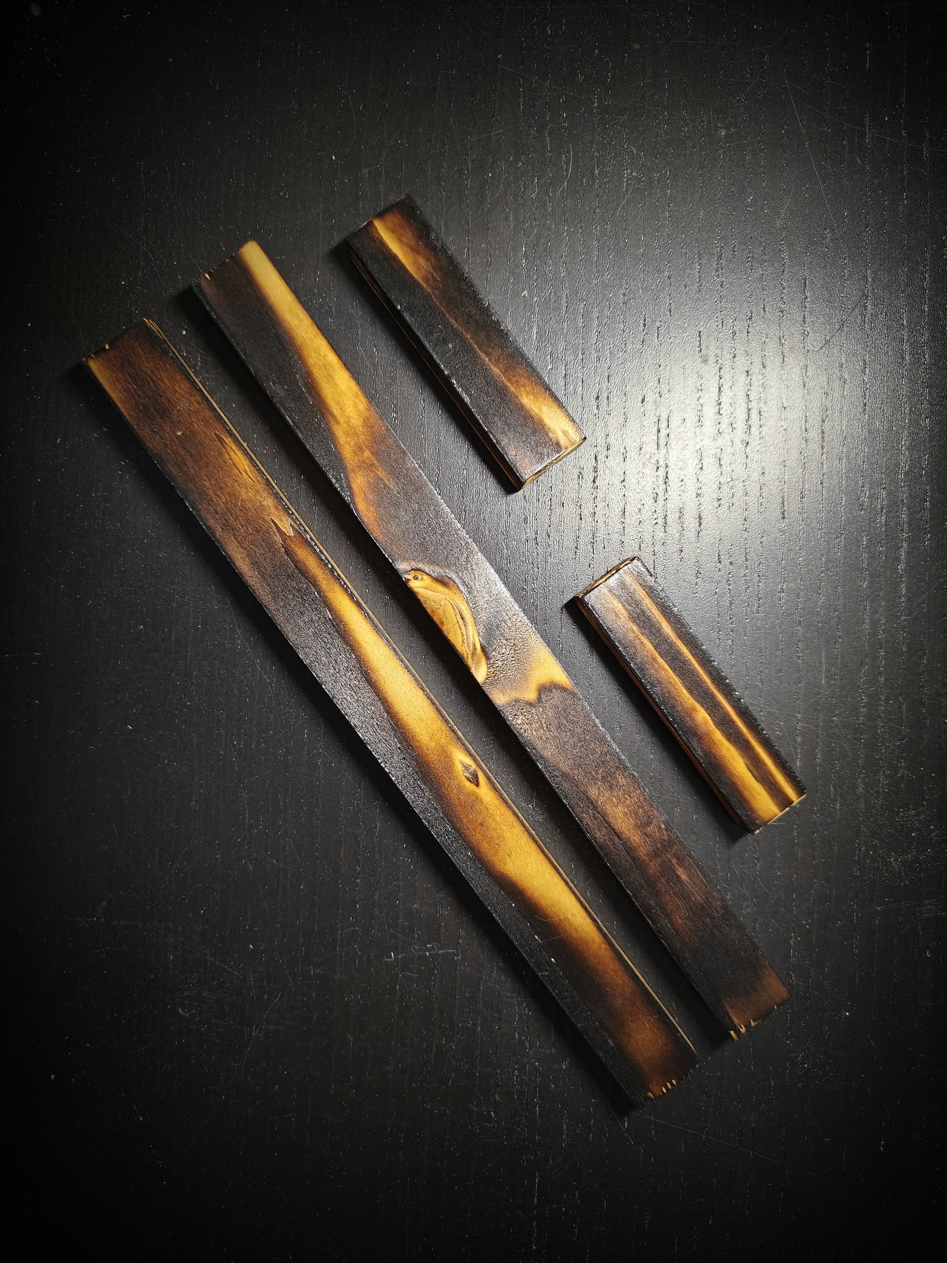
I started out with some spruce scraps, emery cloth and a saw:
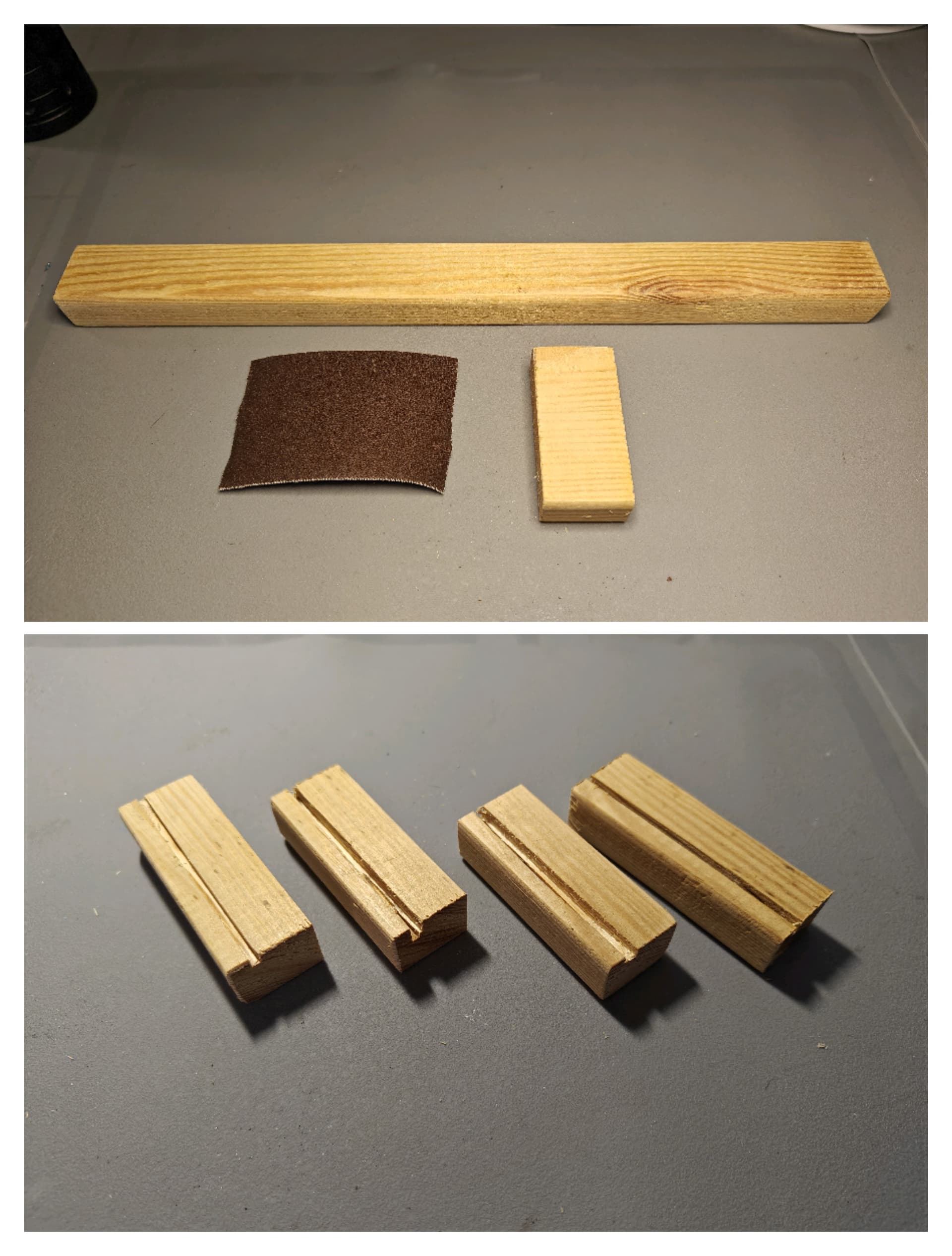
For my first version I made a cut in the spruce with a mitre saw. The bronze plate inserts in the gap.
After watching some youtube tutorials on a burnt wood finish, I took the blocks and held them above a ordinary lighter to test the effect:

After a quick wipe with some paper towel to clear a bit of soot , it didn’t end up like I expected. Maybe I’ll have to use a gas burner and be a bit more persuasive.
Anyway, here is the before and after:
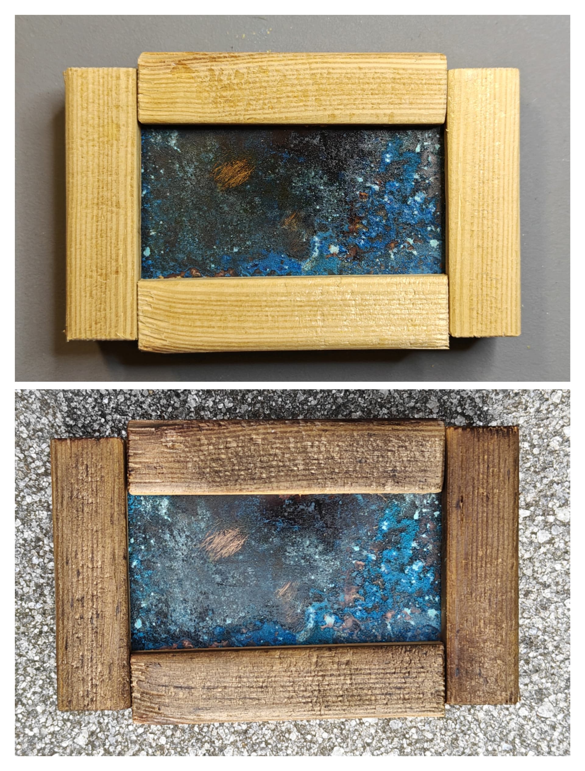
I did end up finding some spruce plank that had more grain and even some knots in there, which will probably have a nicer burnt effect than that piece of scrap.

05/10/2023:
So… Plans change…
I am having so much fun trying to “invent” new and quirky things to add to this build. I might have a worlds first… Stay tuned!
Since it turned from a lumen monster into a desk light - I am going to go for less output. How much light does a desk light actually need? As long as it is efficient and pleasant - it shouldn’t matter. I’m switching over to a Convoy Buck 22mm 3V8A driver for now (which is still on its way).
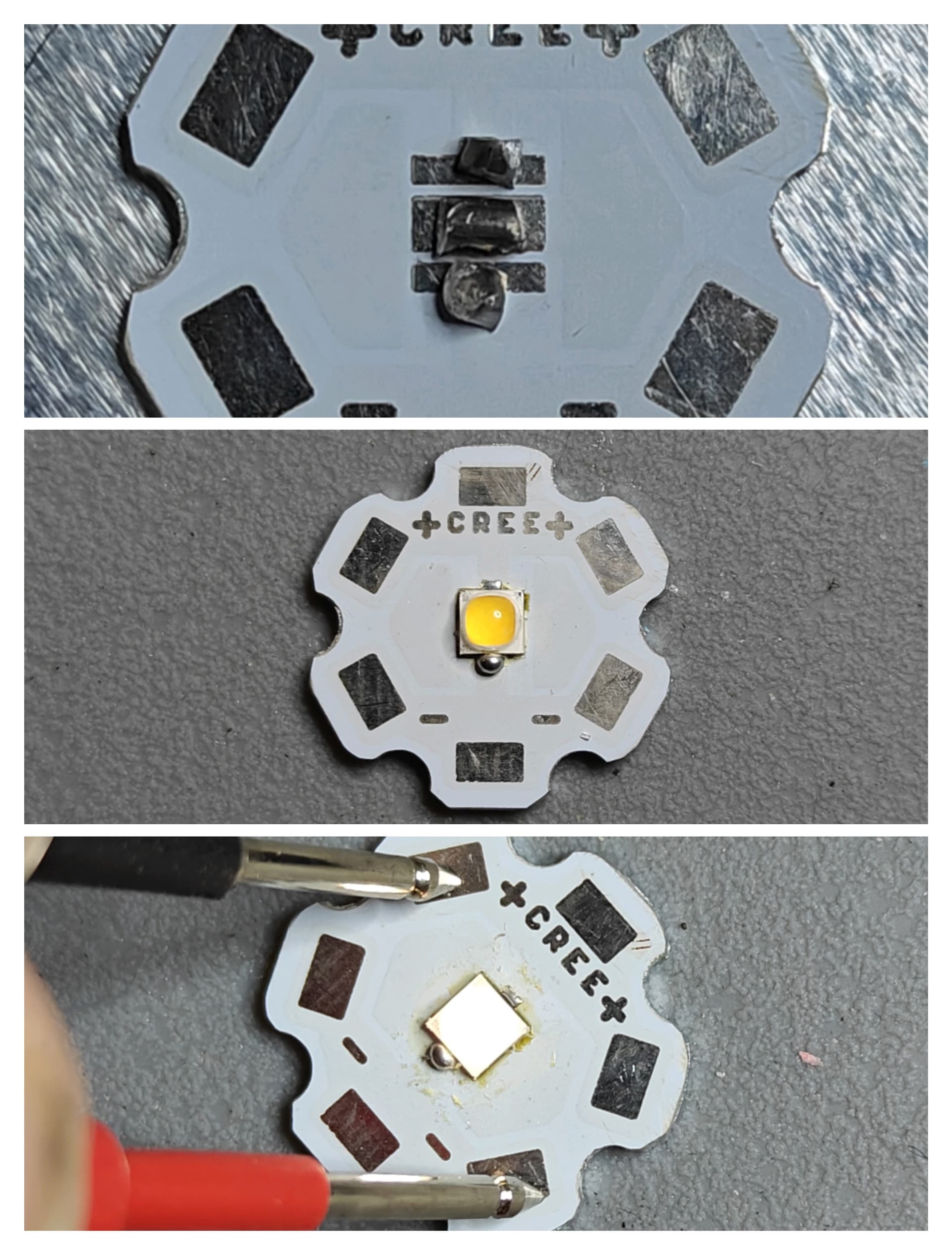
I start out with a generic 3535 20mm MCPCB and make it fit the intended housing with a micro-file.
I shaved down the edges, in the middle pic you can see the difference:

Chosen emitter: Nichia 519A 5000K (3535, 3V).
I know, I know… Can it get more cheesy?

I reflowed it on to the board, but just to show you, you don’t need fancy solder paste, I used clipped flux cored solder wire to reflow:
5000K is too cold for an antique, shipwrecked bronze desklight in my opinion.
So I:
- dedomed it with a plastic spudger
- scraped + sliced the edges with a blade
- soaked it in IPA for a thorough clean

Now this is all pretty standard stuff.
Why not patina the MCPCB? So it matches the rest of the build. It will be a visible mule board, so I don’t want the “CREEEEEE!” being an eyesore.
Those that were paying attention might have noticed the polarity is reversed (+/-), and that there is a solder blob on the cathode side. This is all I need to know further on in the build.
So for the patina, I whipped up some acrylic black base paint, some bronze, blue and green metallic paint:

Using the smallest brush I had:
- black base coat
- bronze layer
- blue and green layer to form “the patina”
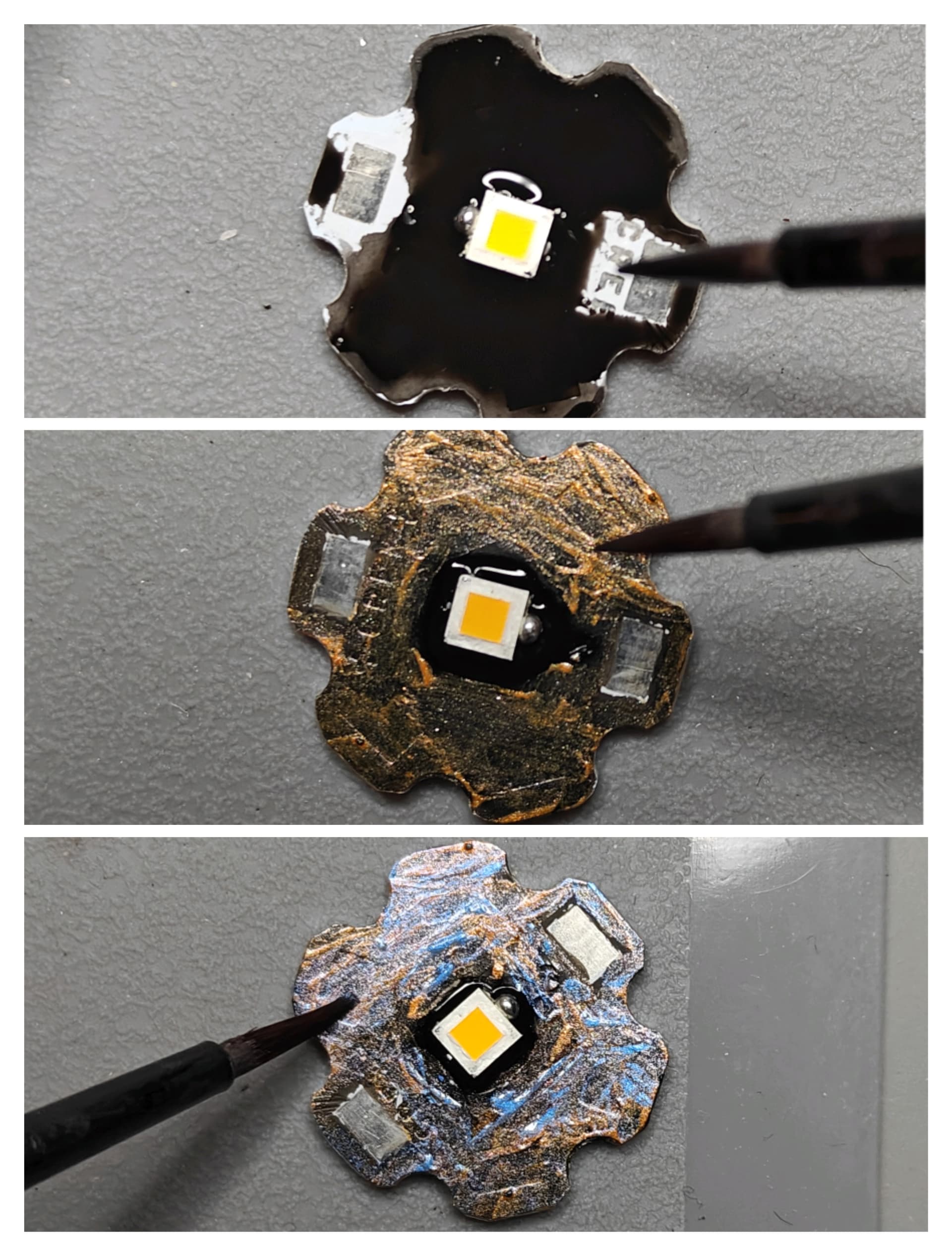
Here is the finished result for now. I can go back and touch up if necessary:
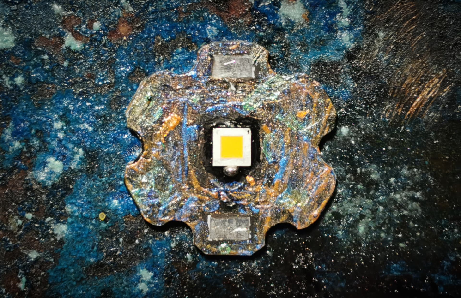
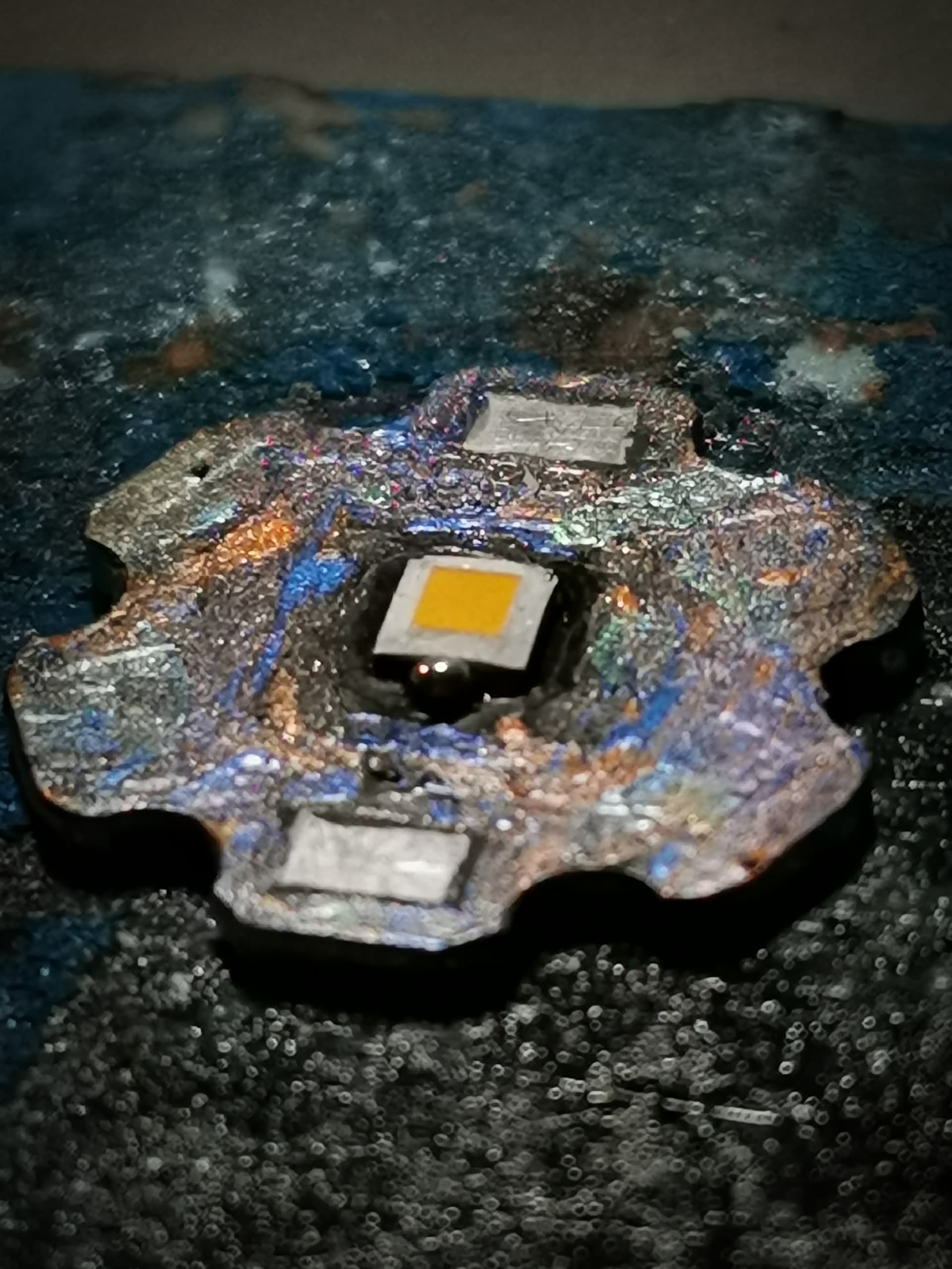
I kept cathode and anode terminals bare, so I can still solder to them later on:
That last pic also shows the dedoming effect. Around 3700 ~ 4000K-ish and a peachy DUV- is my best bet.
That’s it for today.
I understand that it might be pretty polarizing painting an MCPCB… But what do you think? Does it fit the theme?
08/10/2023:
So a small update on the emitter housing:
I cut the threads off a mild steel bolt:

My idea is to drill, tap and press fit this in to the main bushing. This will then connect the emitter housing to the M8 sized gooseneck (still waiting for that to arrive).
Drilling and tapping:
Pressing both parts together with my high-tech 8-in one combination tool (a simple bench vise lol).
The results were not what I hoped for:

Cracked the bushing… Oh well…
Let’s try again, this time I shaved of a couple of mil’s on each angle of the bolt. I also redid the entire thing as my first drilling attempt was pretty off-center

L to R:
- Attempt 1: cracked bushing
- Attempt 2: off center hole
- Attempt 3: Succes! And added a stainless steel M8 ring to tidy it up a bit.
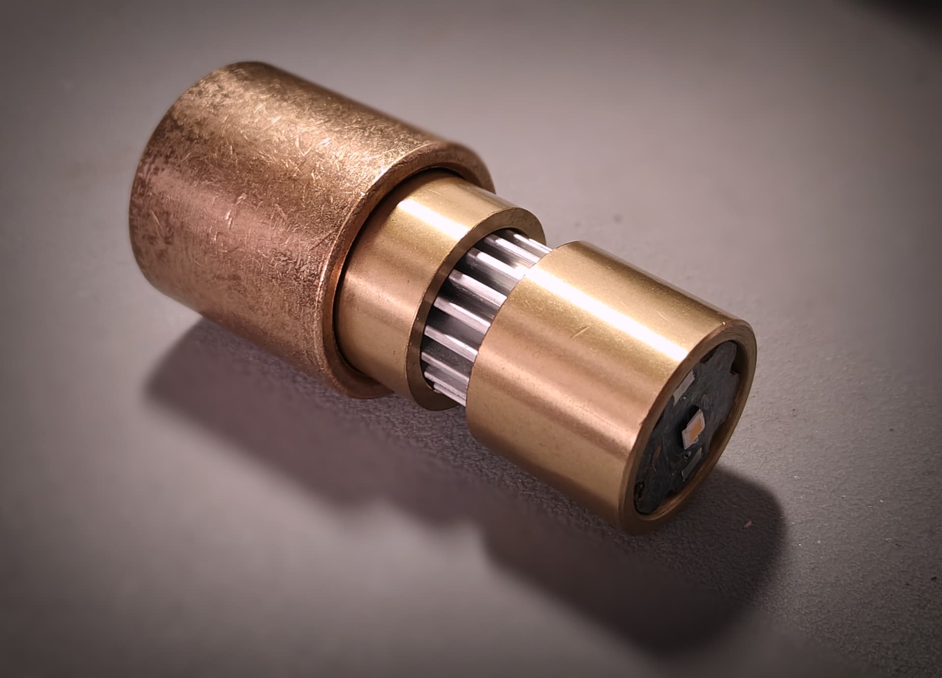
These are all the parts for the emitter housing so far:
I added a thick copper pill for extra mass to help with thermals.
Assembly of the housing goes as follows:
- Start with the pressed, sintered copper bushing
- Drop in drilled, copper pill
- Drop in first brass bushing
- Drop in Aluminium heatsink
- Slide over a second brass bushing
- Mount painted emitter MCPCB

The end result will look like this when all soldered together (if that is even possible ![]() ):
):
The MCPCB will sit a bit further down, didn’t press it in all the way. It is a tight fit atm.
There is only little problem I have to solve:
The wiring is all through the center of the housing, and this MCPCB is designed for leads on the side…
Hmmmm… ![]() Triple?
Triple?
I also weighed the entire setup, 205 grams(=7.2ounces) so it is a heavy setup for such a small package.
See you later!
10/10/2023:

Oh boy… Here is the time I get grounded and realise how much I suck at woodworking.
I only have a jigsaw and a mitre saw, so that’ll have to suffice:
Test fit:
Duplicate it and cut the rest of the skeleton:

Dissasemble for sanding scorching with gas burner and clear coating:

Results:
Burnt off some weeds on my pavers too ![]() :
:

Final result for the top of the housing (bare bronze):
Next is the patina for the bronze. Should’ve drilled the holes first but oh well, we’ll see how it ends up.
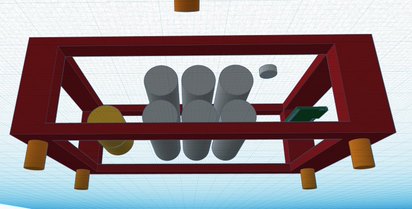
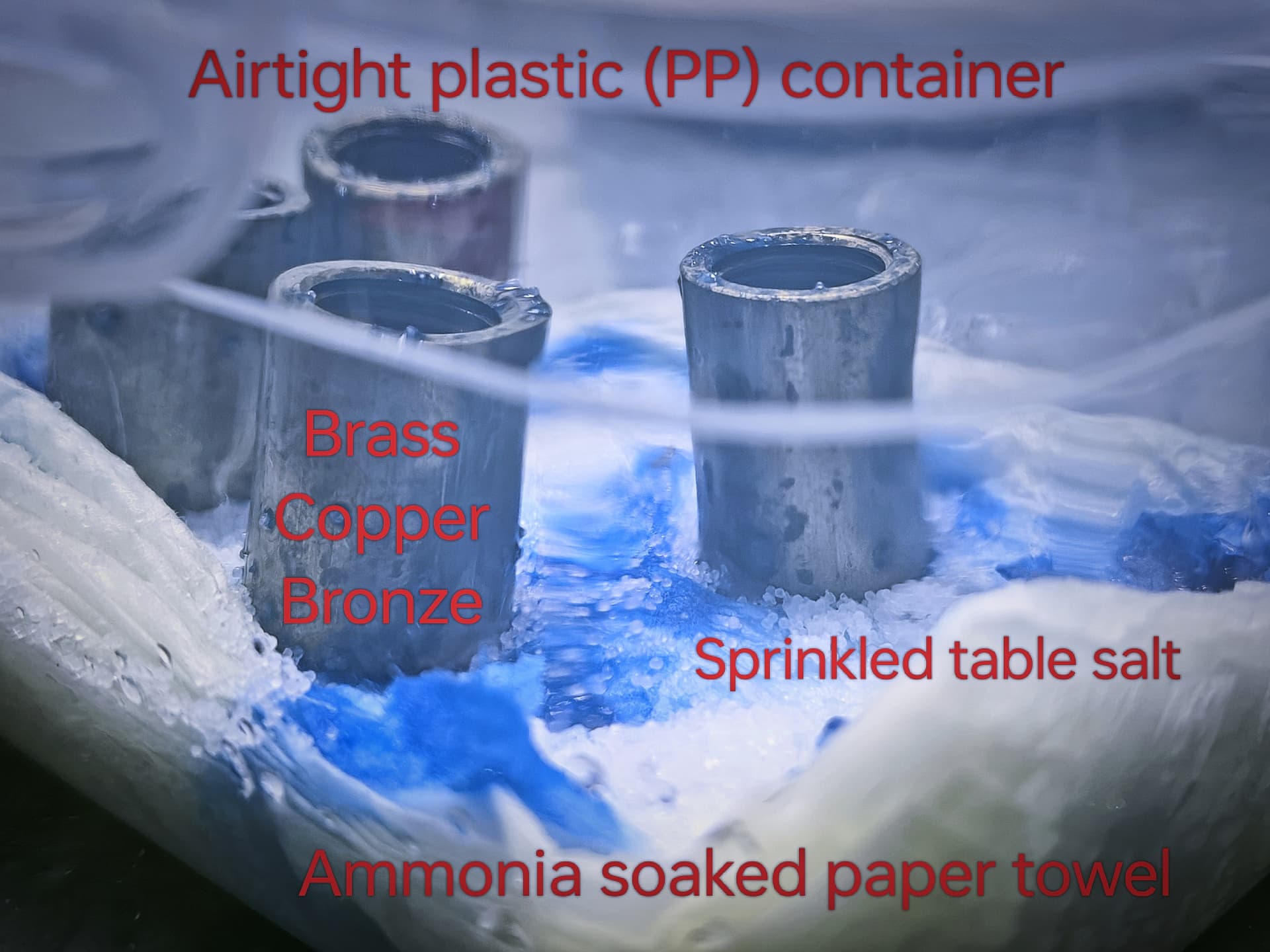
Lots of breath holding when handling the ammonia!
- Airtight container
- Bronze plates sprayed with water
- Table salt sprinkled in the water
- Ammonia container inside (on the left) for fumes
- Let it sit and check on it every couple of hours
The ammonia will fume, and make the bronze and salt react with water and carbon dioxide.

After 30 mins you can already see the reaction and have some blue show up:

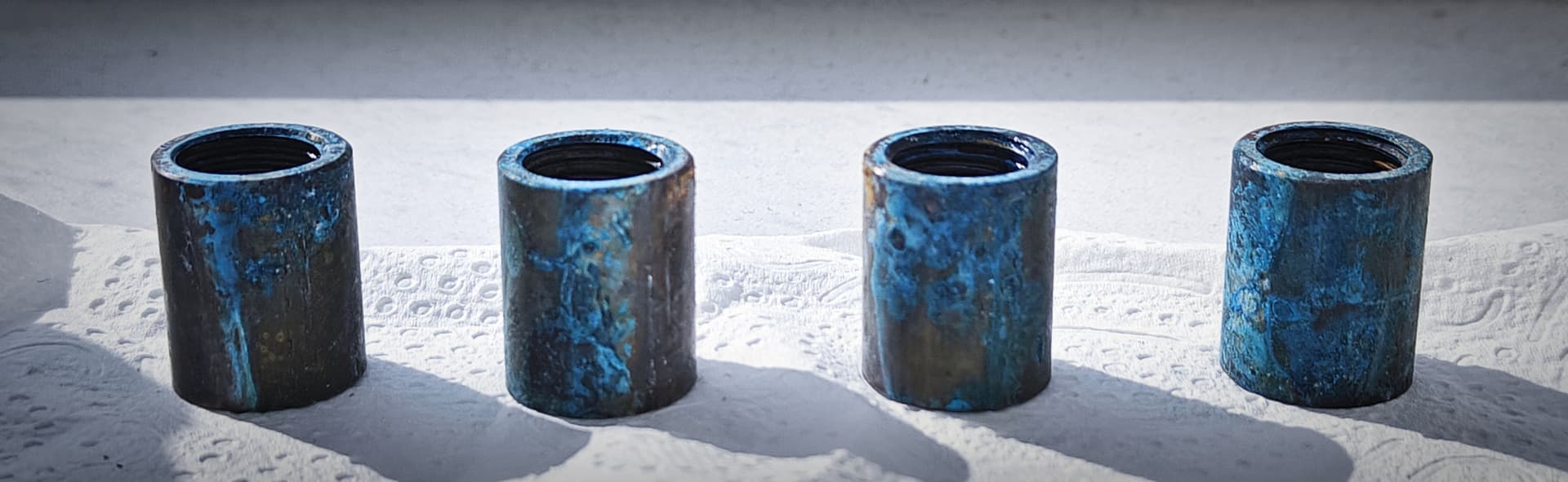
How it turned out ~6 hours later, after a rinse in hot water and drying with a hairdryer:
Out in the low sun before the clear coat:

12/10/2023:
So for today I am tackling the battery…
As I am doing a 6P setup with:
- 6 x 3000mAh = 18000mAh capacity
- 6 x 30A CDR = “180A” CDR (lol)
For a desklight mostly encased in very conductive metal, I am adding some extra built in safety on the battery components.
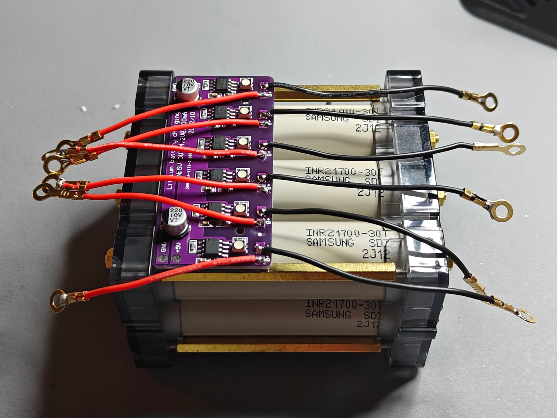
6 x 21700 battery holder (which can be infinitely expanded (In my case, I could daisychain 3 of them):

Setting up in parallel:

On the charging side I found this neat little board that has 6 (the magic number it seems) TP4056 charging modules.
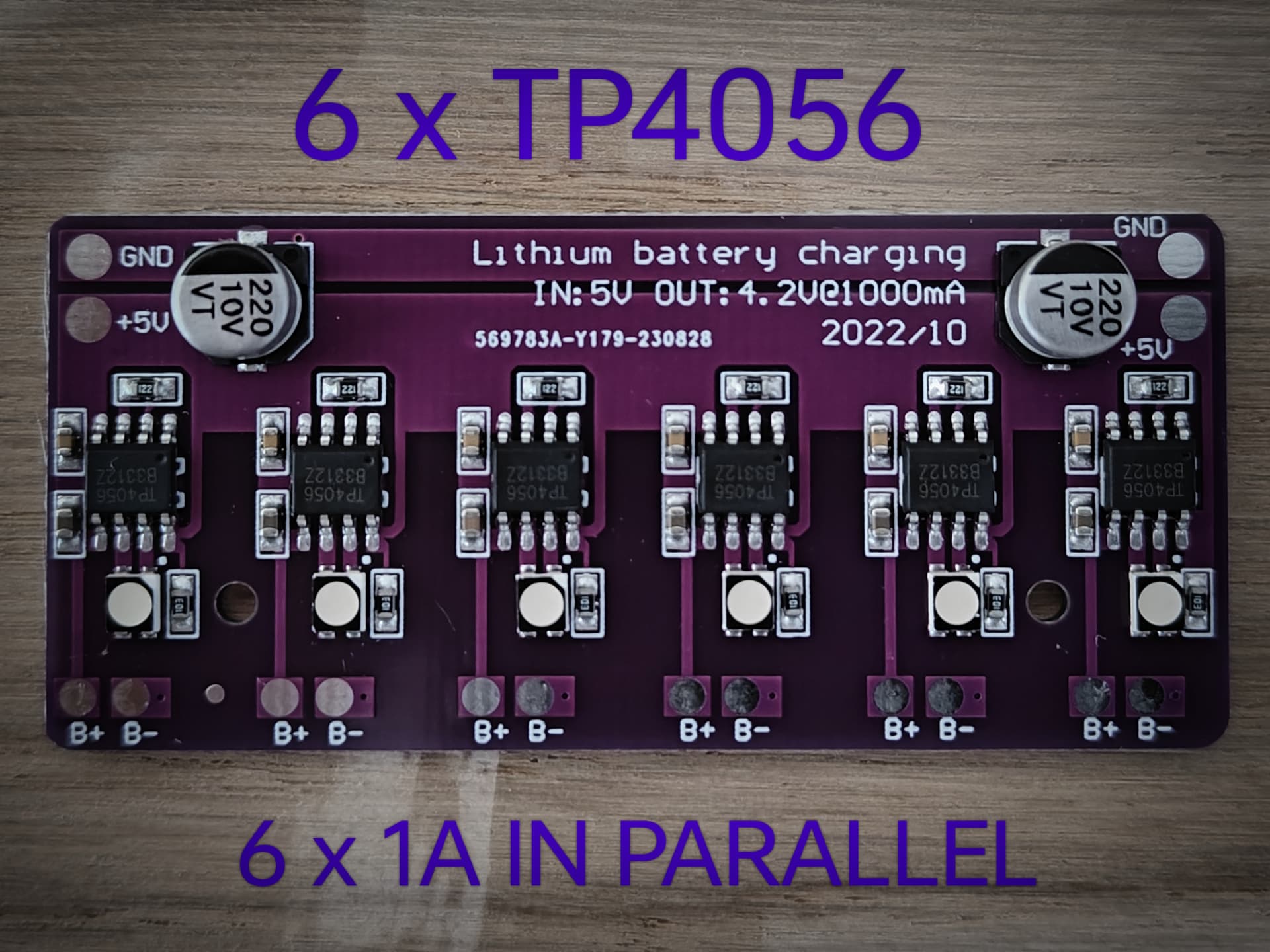
I decided against going for a power bank setup. While it is a neat feature, I know I will never use it for that purpose as I already have multiple, which I don’t use either. And it is one more step and power switch to worry about.
Each module on the board charges at 1A, and I will be wiring them in parallel.
I used some crazy, sticky, transparant, double sided “tape” to afix the board to the battery capsule.
It will be powered by a 2 wire USB-C connector (will be drilled through the bronze housing):

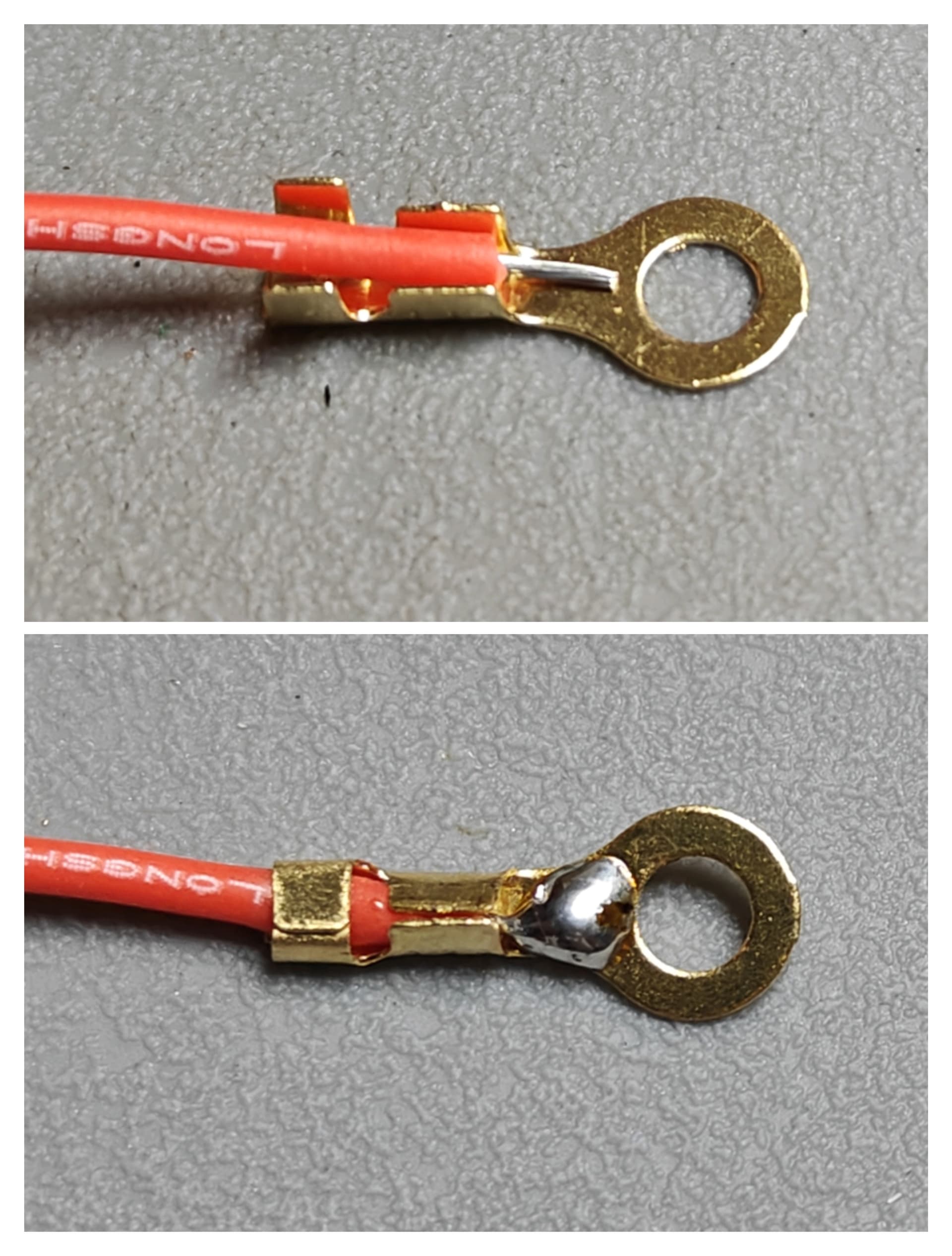
Preparing the wiring:
- M3 circular crimp terminals
- 22 AWG silliconed wire (for 1A per couple)
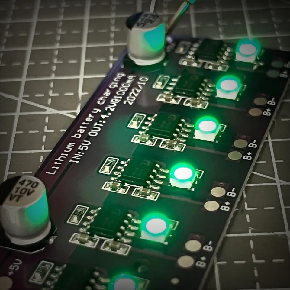
IT IS ALIVE!
I feel it almost looks like a time-bomb from some action movie…
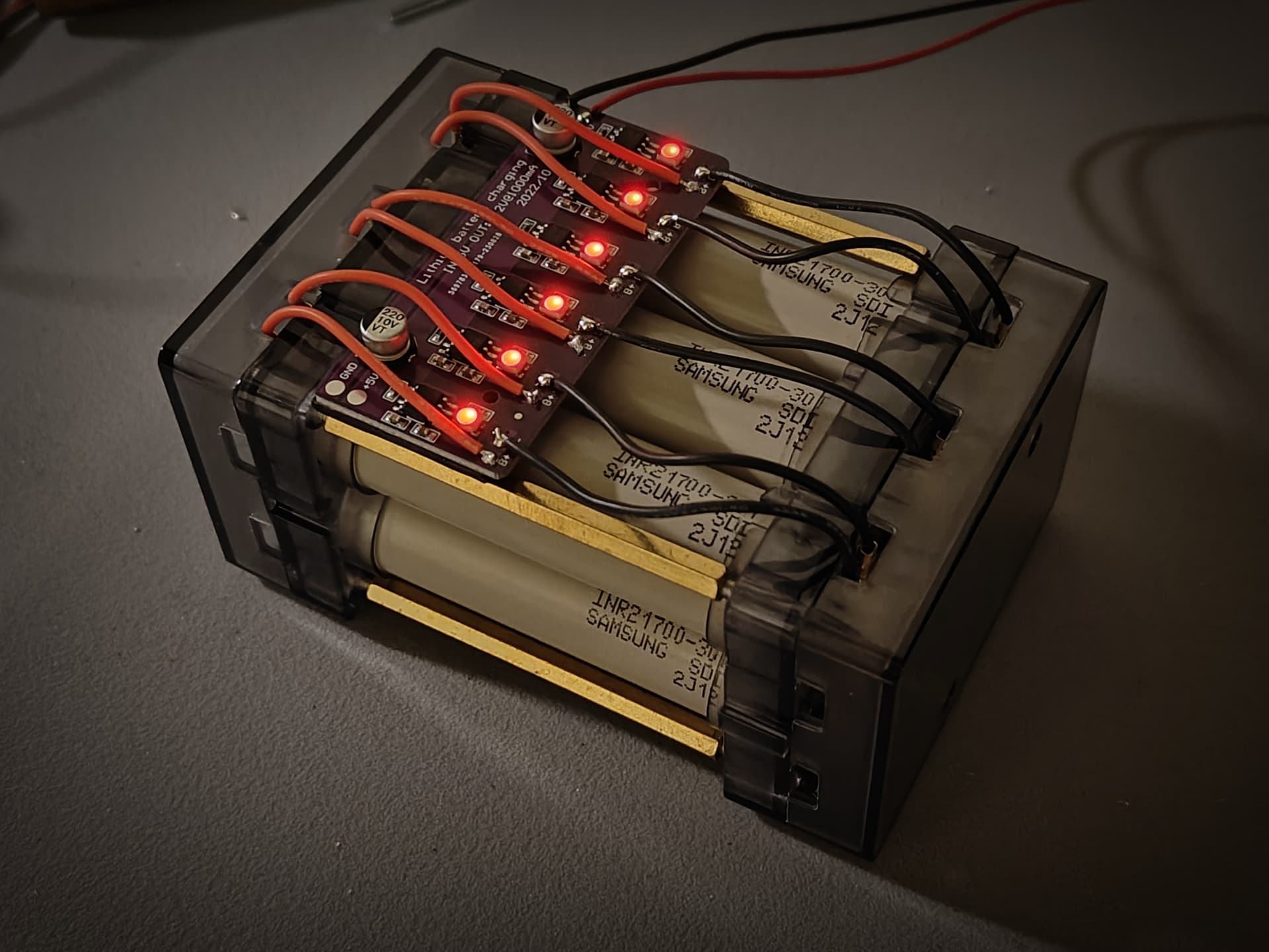
I’ll do some tests to see when and how it terminates the charge. Atleast 6A should be plenty low.
Safety first. If anyone more knowledgeable than me sees a problem with how I set it up, please let me know!
06/11/2023:
I haven’t updated in a while since I’m busy with renovations IRL! Some more tidbits arrived and Iam close to completion. Just need to figure out the assembly and wiring.
I want to have a shutoff, disconnecting the driver from the battery. I thought this switch would work nicely:
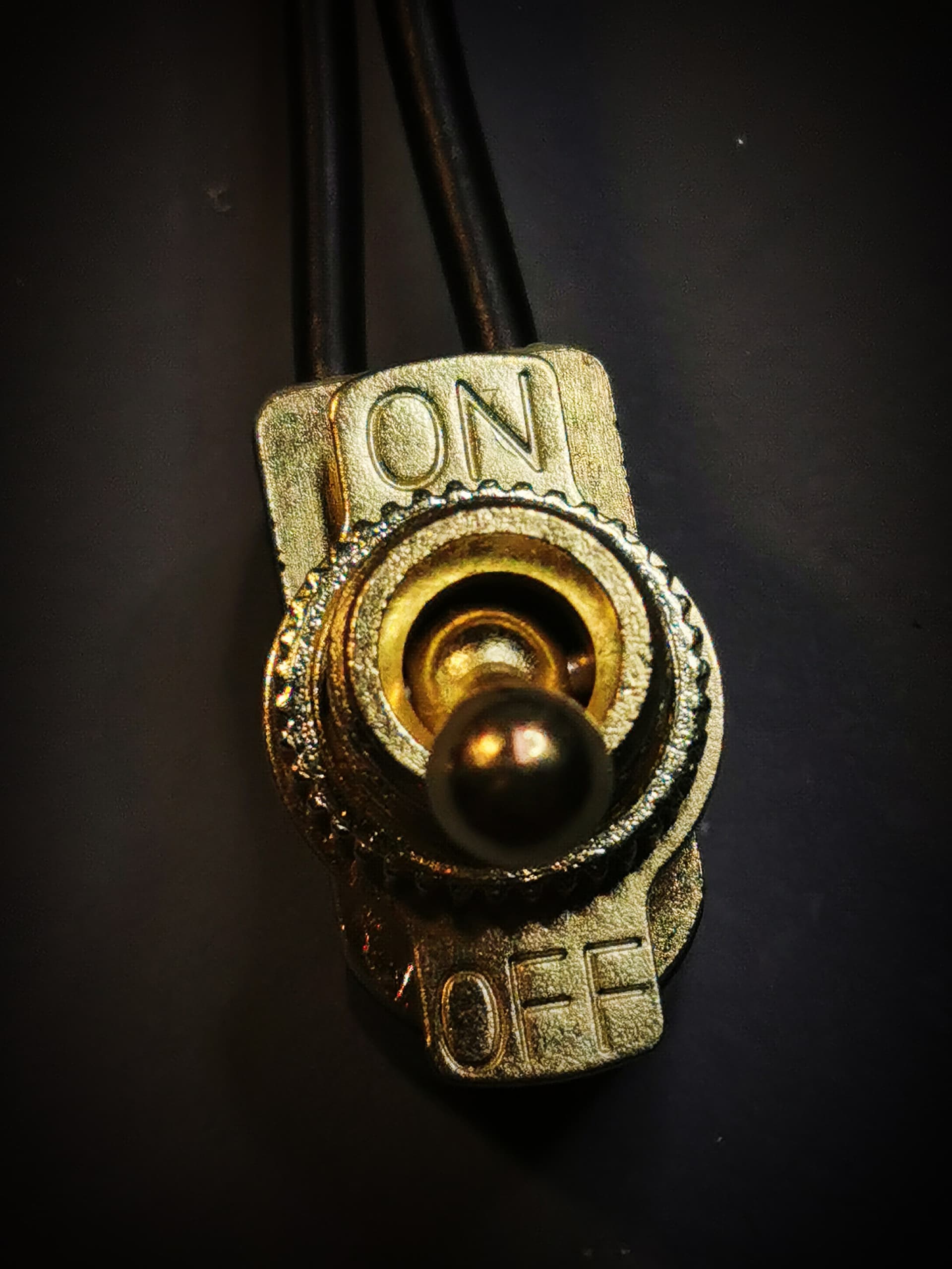

It will be wired from the negative terminal of the battery to the negative terminal of the driver.
Should I mount it on the visible side or not ?
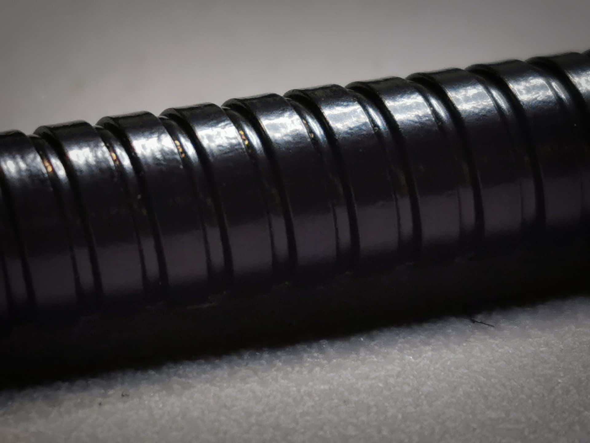
The flexible gooseneck arrived. It is 50cm long.
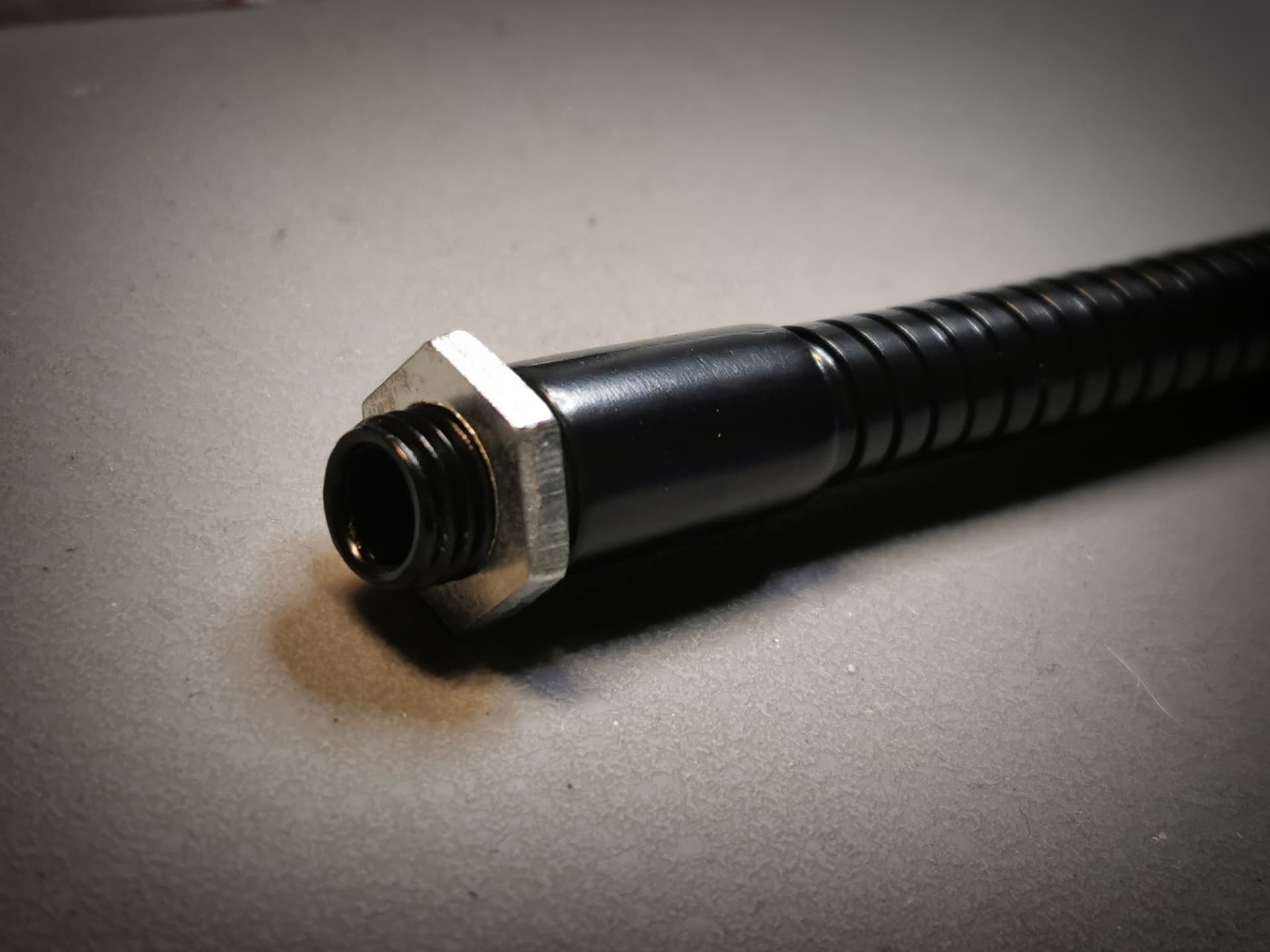
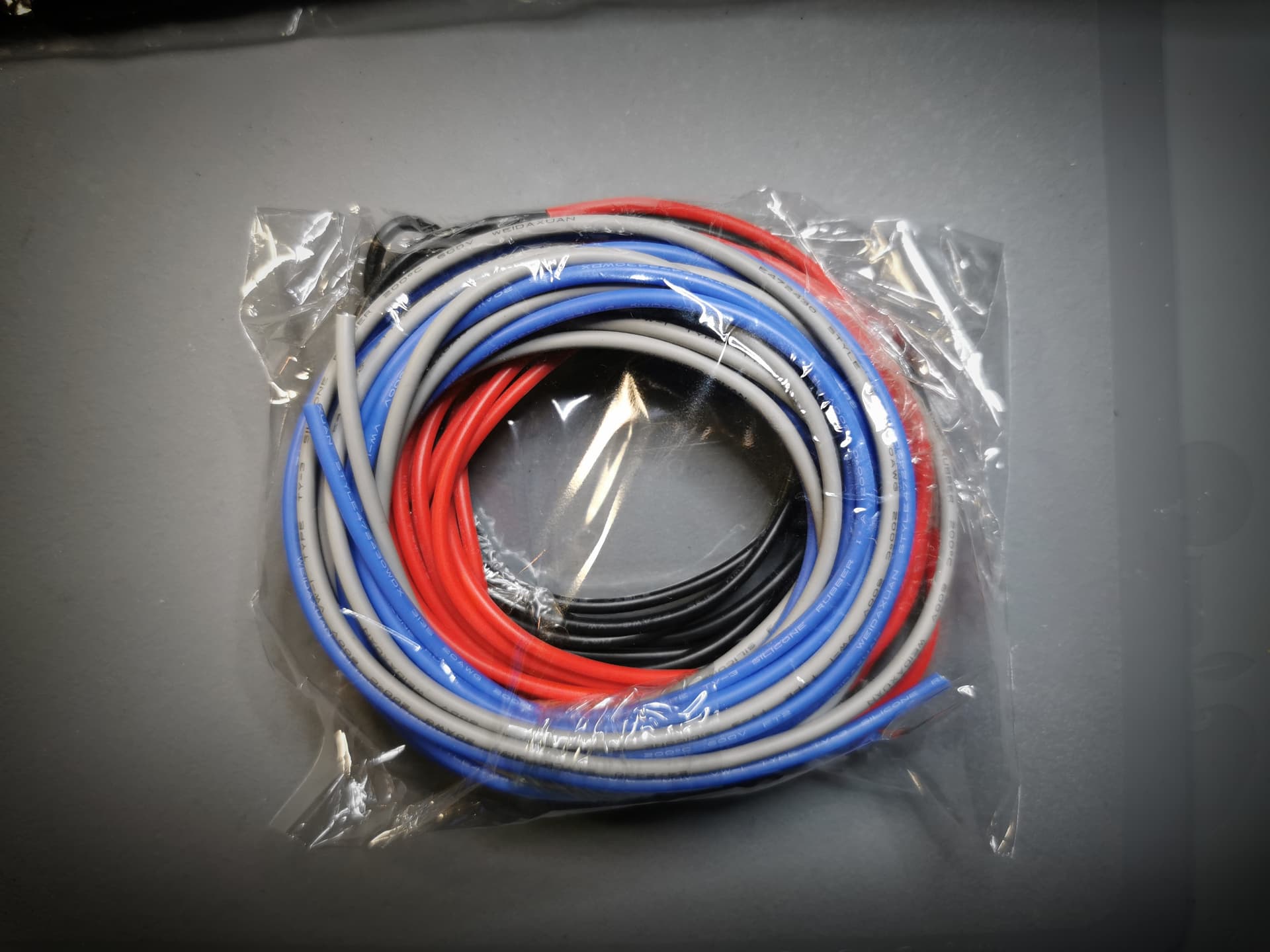
And here is a loom of 20AWG that will be used for the connections.
Feeding the thick sillicone wire through the gooseneck was no easy task… I had to use a lot of oil to lubricate the inside! It is a tight fit. It took me half an hour of tugging back and forth on the delicate wires !

I was waiting for 3 x 219B from KD but their shipping is … Lengthy to say the least.
I think I’ll have it up and running with the 519A at the end of next weekend ![]()
08/11/2023:
Today I assembled the head and mounted it to the neck. I had to figure out the two part assembly, which took me multiple hours of cursing. Also didn’t want a red and black cable visible on the emitter side, so I spliced them inside in the housing.
Here goes nothing…
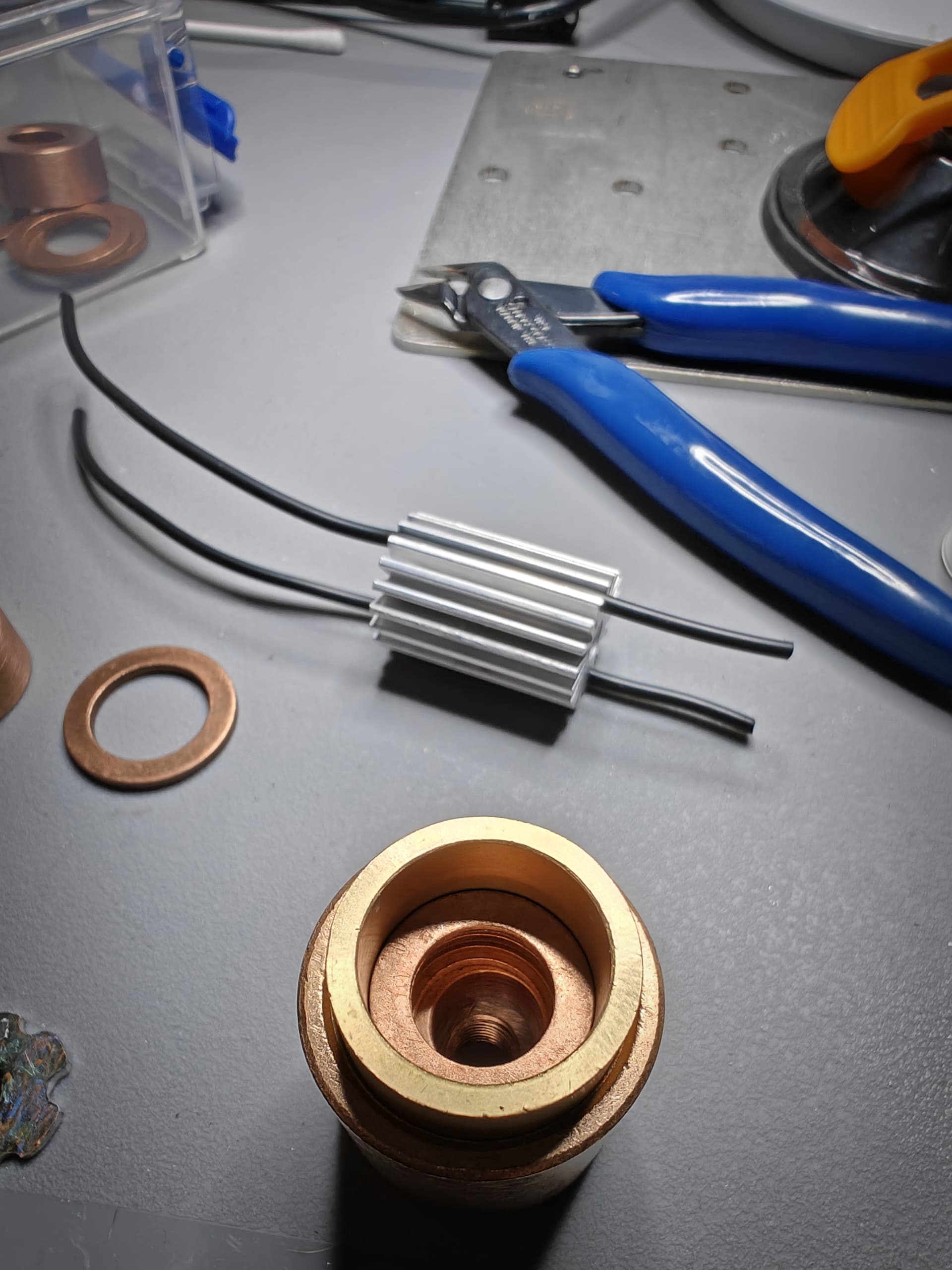
Heatsink with the wires: the 22AWG wire is a tight fit between the fins of the heatsink.
Emitter assembly fused with the heatsink, ready for soldering:
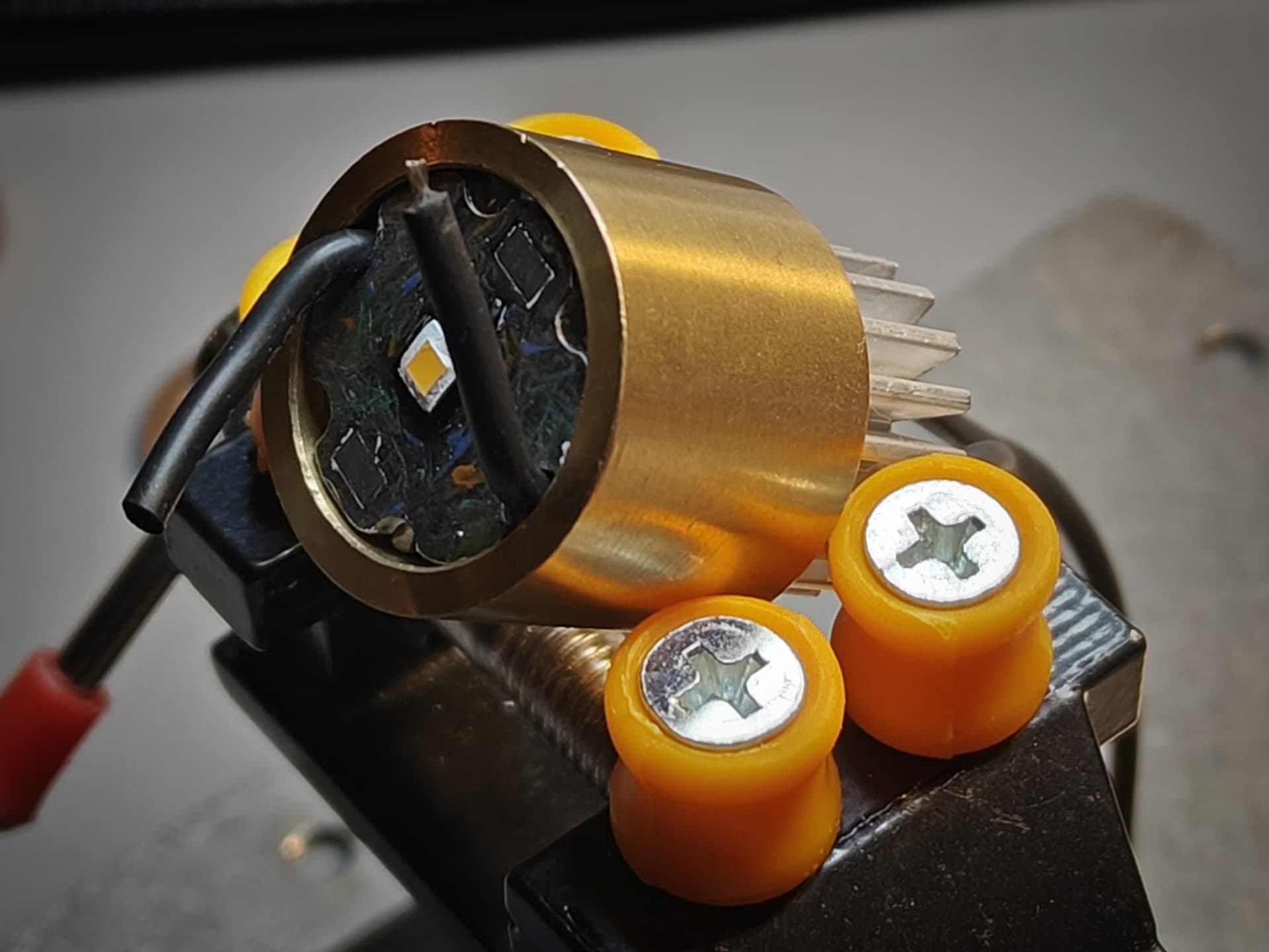
All soldered up: I tried to make everything as neat and symetrical as possible… I hope it shows ![]()

I might try to paint the wires later on? No idea if the paint will adhere…
Main body and lower connecting neck: wires and parts need to be fused together.
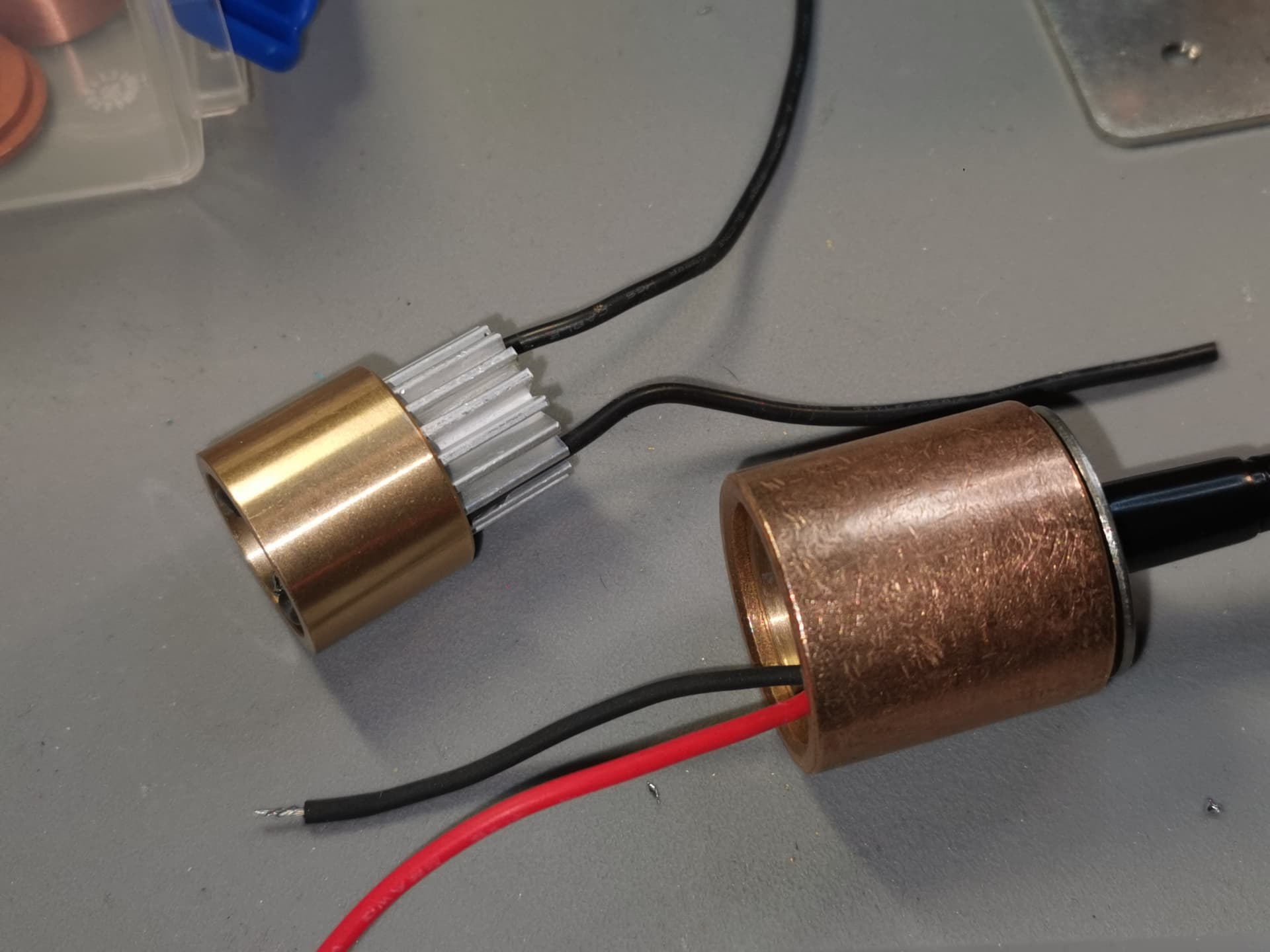
Soldering all 4 wires:

Some heatshrink tubing to finish it off:
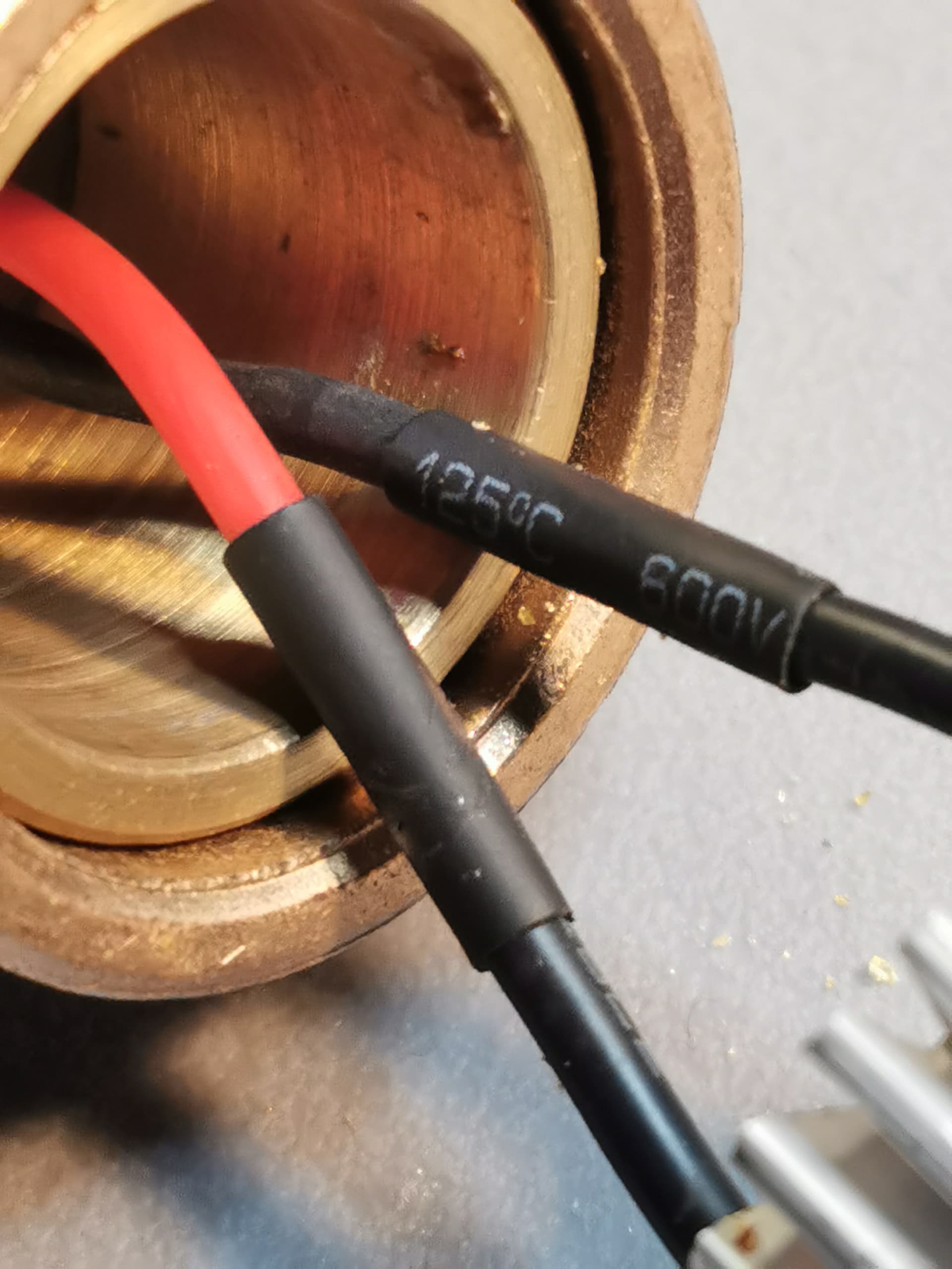
Pretty hard to get done in such a cramped space! I then pushed the wires in the housing, giving me a bit of leeway when positioning the neck - as there is no inherent strain relief.
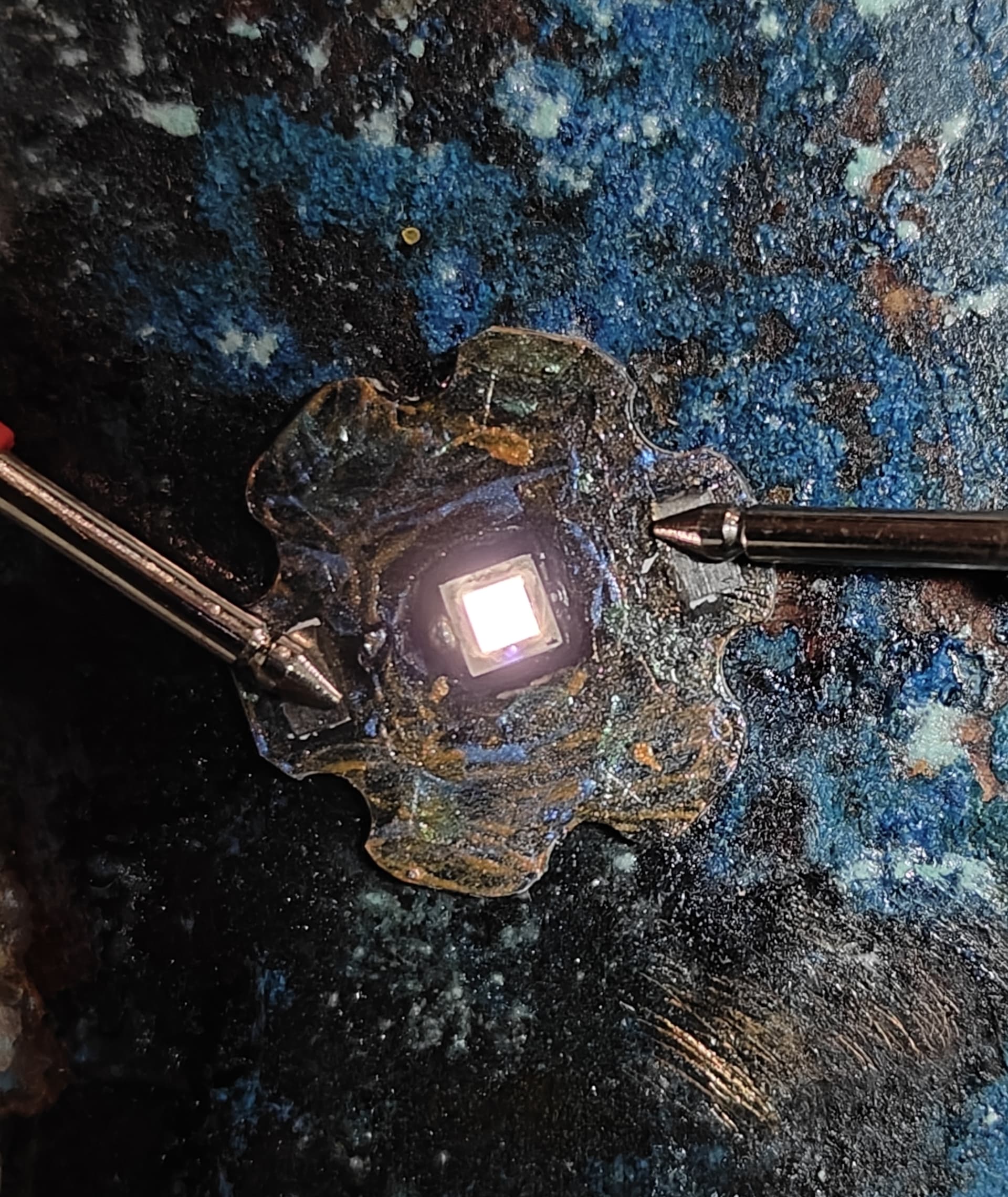
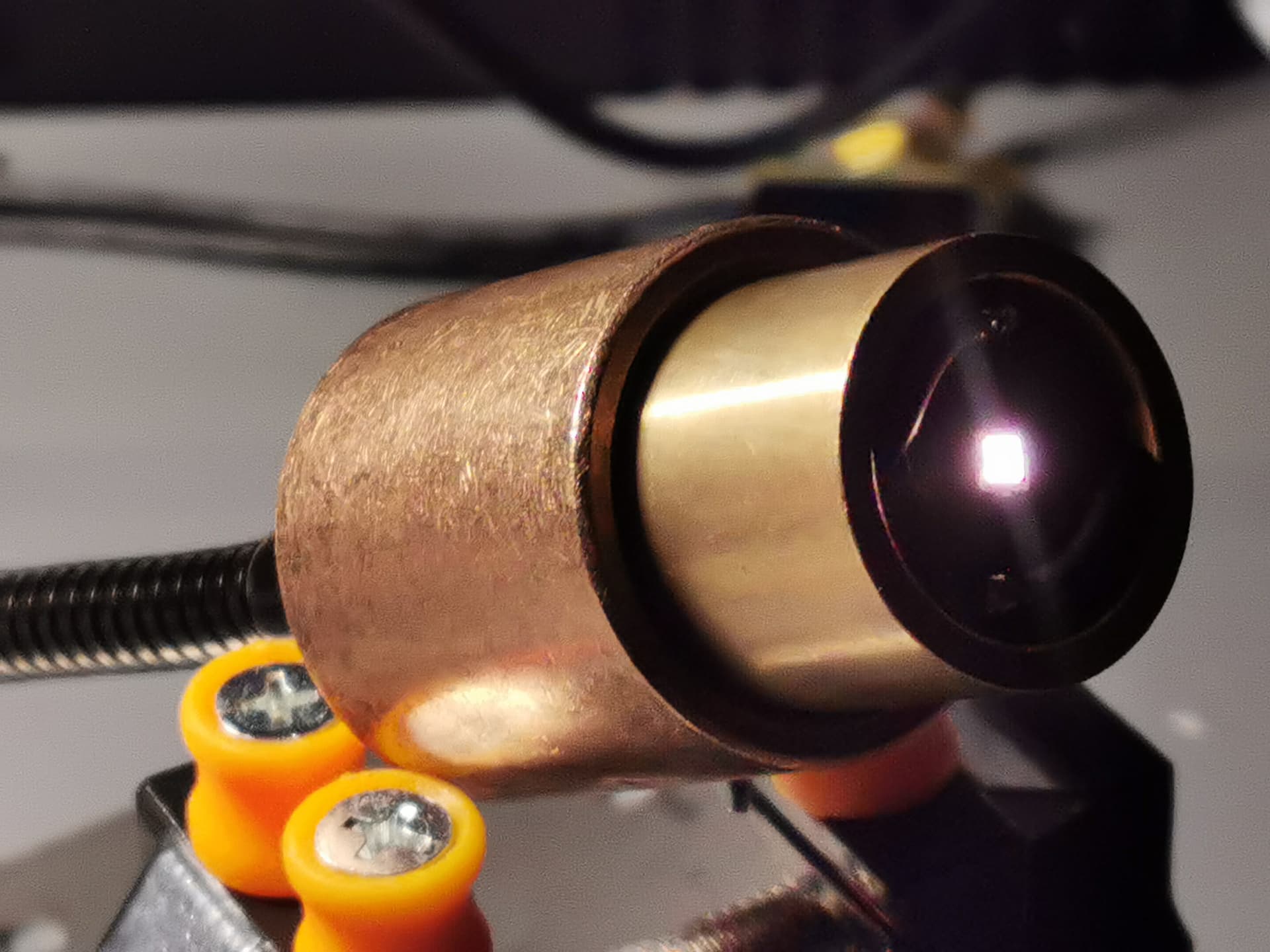
When you stare into the Abyss for long enough…
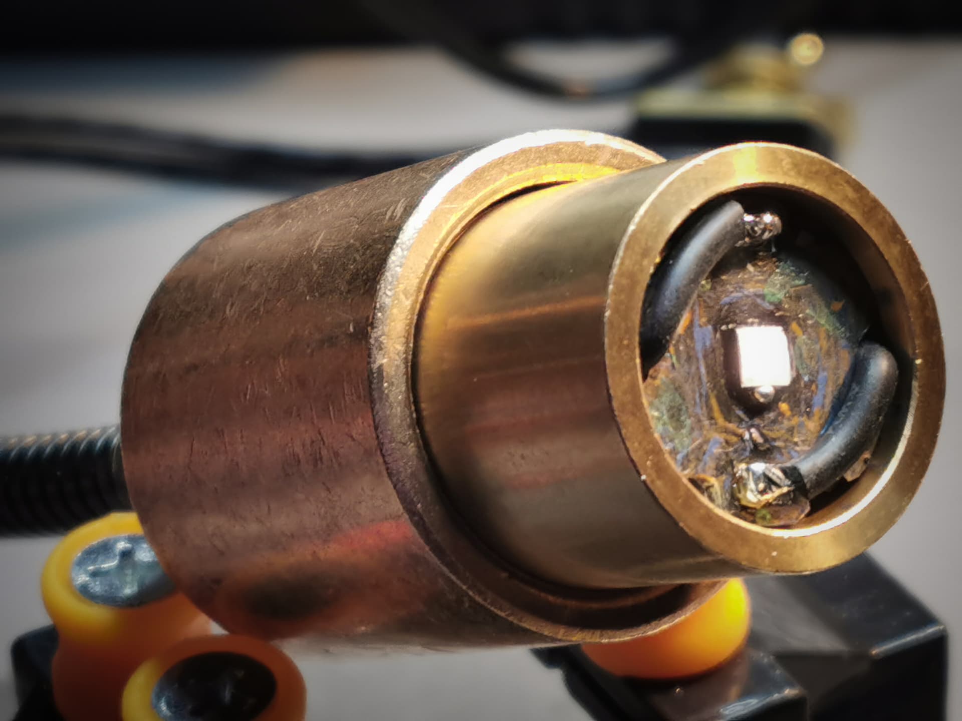
The Abyss stares back at you!
Probe check: succes!
Last 2 steps are finishing the wooden and bronze body + final assembly… I think?