Help me choose a current for a cheap-o host mod

So I have this old ultra-cheap host that I’d like to upgrade but I’m concerned about heat dissipation and unsure what current to feed it. This weekend I read through a few dozen old and very old forum threads and didn’t find an easy gimme answer to this, but did see one about a similar host/components (without a final solution) and an interesting one from Barkuti about bare-board dissipation.

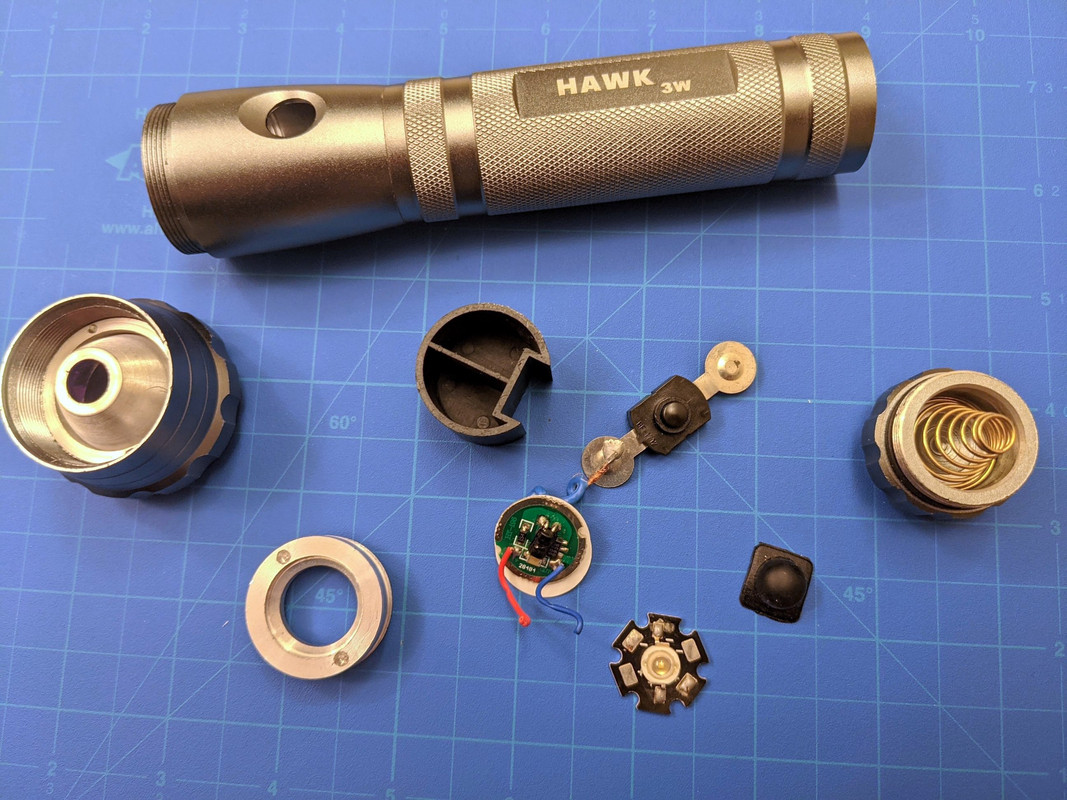
Picked up this “3 watt” light maybe fifteen years ago for a couple bucks. Now I’m going to spend about $35 to turn it into something useful. lol. It was a 2-C cell light with an old cheapie emitter, pretty much junk, but I made a plan to refresh it. Picked up some Keeppower protected 18500 cells (Panasonics), found that the reflector and lens for a Convoy M1 fit perfectly into this host, have a new switch on the way. 20mm mcpcb and 20mm driver. But the big question is how much heat this can handle, and unfortunately I can’t test the output of the original driver since it died long ago (assuming it was less than one amp).

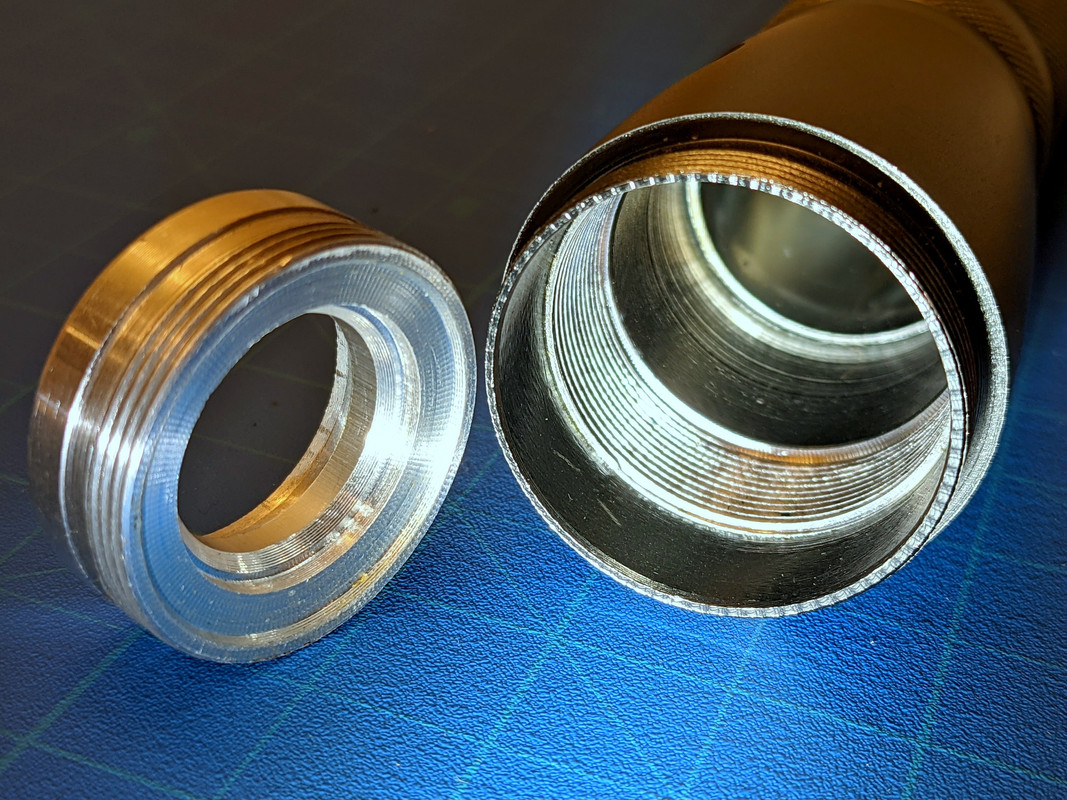
It has one of those dang hollow donut aluminum pills. The mcpcb has maybe a 1mm ledge to rest on but most of it is bare-air…straight down to the driver. There is some mass, but that big hole of dead air. About 8mm space or more, so I can fit several buck driver designs in there (already have a couple of them from MTN, one on the way from Simon, and will likely be ordering a few more from KD just to have around). Using a 20mm —> 17mm adapter ring might gain me another smidgen of space.

I’m considering adding some of those silicone thermal blocks in the space but I don’t necessarily want to transfer heat down to the inductor or driver components either. I could possibly do a copper plug or solder a penny or something, but really I’m not sure how much heat can nicely transfer from the pill to the host body since the threads are somewhat loose and the pill is rather short anyway (will likely put a little thermal compound in the threads, messy as that is). The head is fairly thick and uses a thick aluminum retaining ring to secure the reflector, and the M1 reflector being aluminum may help in heat dissipation vs. the original plastic one. The main body isn’t thick, no fins, but it’s not super thin either.

Emitter choice is undecided at the moment until I have an idea of the buck driver current…sticking with 3V, though, and considering LH351D or SST40, depending. Or…would a 6V emitter put off any less heat in a buck at lower currents?

Other than swapping a couple early emitters, I didn’t get into modding lights until I had many with good host designs, so I’m not sure what these old cheapie hosts are capable of. I’d prefer not to unnecessarily fry a driver or emitter if I can help it. I’m thinking that 1A should work just fine….what about 1.5A or 2A? This host may have less cooling ability than an S2+ body, so going above 2A with poor sinking seems like maybe a bad choice, despite being larger in diameter.

Going for simple single mode utility light here and +/- 350 lumens would be fine, but more would be nicer of course. What would you suggest for current, what have you found in cheap mods like this?

!https://i.postimg.cc/Pfg7x8GL/Hawk-light-parts-2.jpg !

Most cases, I doubt they’d drive a 3W LED at the full 3W. Teeny little chips inside…

Boost converter that small would rarely push more’n ½ A or maybe ¾ A, so figure 2W max.

Always handheld and left on for, say, 15min max? I’d stick to 2A max. (~6W, 700lm)

Possibly left freestanding and for extended times? 1A max. (~3W, 350lm)

Some people don’t mind torturing LEDs, but I tend to be more conservative without ATR and the like.

All that presumes an emitter swap to something at least G or L class, not the same “bead”-type LED.

Yeah…off the cuff guess I’d say maybe it was 700mA which seemed popular back then? No markings on the inductor wrap. The schottky is an S4 which I think is 1A.

I suppose the switch will be fine…new ones on the way are Omten that I can add a spring to.

I don’t mind torturing emitters a little but everything I’ve done has had normal solid pills or a shelf plus a little more meat on the bones. :slight_smile:

Bead-B-Gon!

The cooling ability of the light mostly depends on the total external surface area. The light looks significantly larger than an s2, so it has more cooling ability. People say that an s2 can sustain 1.2A continuously without getting too hot to touch. You might be able to add one additional 7135 to that, so ~1.5A. The main factor here is how well you manage to transfer the heat from the (copper) MCPCB to the pill. If the MCPCB could be soldered in there, that would be great, but it appears to be an aluminum pill. A press fit + thermal compound around the mating areas would be the next best thing. Adding fasteners to hold down the MCPCB would help. I don’t think stacking copper discs and such will be necessary at a reasonable drive current. The MCPCB is a fairly decent chunk of copper in itself so the heat will travel through it laterally well enough, it just needs somewhere to go from there. You could use regular silicone grease in all of the light threads instead of thermal compound. It will still increase thermal transfer and the difference might be negligible between the two.

S2+ at 2A is what I’d call comfortably-warm.

Yes, aluminum pill, very minimal contact with the board. I’ve got a variety of copper boards and some look like they’ll be a good tight press fit with or without a little filing, but that’ll be it…reflector pressure will be very low as well (and more might actually work against me if it bows the board any). I was wondering if that lateral dissipation will actually be enough but that’s the only contact as is. Also am half considering the stupid-pet-tricks with a little drill press milling to flatten the cone a bit to receive a slug that could be soldered to the mcpcb…which would be all kinds of meticulous, but still the question of how well that pill threading will transfer heat to the body (small, fine, and sloppy threads).

Looking like 2A is a good bet.

I just hate having that emitter sitting on air. It’s…wrong. lol

Maybe you could also file down the retaining ring to make it thin enough to make room for a copper board underneath the LED?

Looks like the mcpcb sits on a small step in the pill so there’s more than only lateral / radial transfer at that junction. A press fit would add to the total area of surface contact. The fine threads of the pill should transfer heat well too if you fill the gaps with grease. Does the pill stop against a step in the body, or are the threads the only contact?

More options come to mind. If you sand down the rim of the heatsink to be flush with the “step” and use a larger MCPCB, then you have a whole lot more contact from the MCPCB to the pill than just the step. You could then use a ~32mm MCPCB like the Maxtoch ones mtn sells, or the Noctigon XP32 32mm MCPCB which is 2mm thick instead of 1.6mm. The emitter isn’t sitting on air, it’s sitting on a copper plate!

That’s what I was pondering, end mill in the drill press…doing that freehand inside a small circle, though…great fun (very carefully and in a vise of course). lol. I don’t think I could work any type of file in there to accomplish that…sanding drum and a couple sleeves maybe. Not sure it’s worth the effort, though.

Yes, but that step is like 1mm or a tad less. There’s no bottom stop for the pill, just the end of the threading (with a ton of wasted space back there), but the pill actually stops at the top of the threading where the pill threading runs out and the 4mm shoulder hits the top of the thread entry, if that makes sense. That shoulder doesn’t even contact the host, so I may poke in some shim stock around the circumference. That big plastic slug just sort of sits back there held in place by a little hot schmoo, serving only as a battery stop and a shelf for the switch to sit loosely on…switch legs fold over the edge of the plastic and down into the battery tube. Cheep cheep! :slight_smile:

That’s a good idea about flattening the pill rim…like a convoy triple. Could use/shape a 30mm board (29.5 pill dia.) and since the retaining ring for the reflector actually does a great job at keeping the hole centered over the emitter, that might work well. Would need to fine tune spacing probably, since the M1 reflector is a bit longer than the original (planned on this anyway since the emitter will also be lower than the ol’ bead type). I’ll mull this one over. I wonder if that would add enough to make 3A feasible.

Here’s a look at the bottom side of the pill with the driver ledge, and inside the host…that ledge in the rear is the battery tube (pressed in).

Any chance of The Penny Trick?

Ie, old Cu pennies (not Cu-flashed Zn), grind flat, trim to press-fit into the hole.

Yep, although I have some slugs I’d probably try first (pure copper). I think I’ll run without it at 2A and see what it feels like, then maybe look at increasing mass. Mo’ metal \m/

Now to decide on which emitter…

A ’351 is a good all-around LED.

Probably what I’ll go with and I have a variety of those on hand now. SST40 or XHP50.2 might be interesting and should do ok in that reflector if they don’t look ugly at lower amperage.