I would like to get me some deep UV lights, so I bought a 2W 250nm (5-8V Forward voltage) and a 2W 280nm same VF. In addition, the mentioned 20mm driver with 6V from Convoy and 2 S21A hosts. I also got me the Buck Boost driver in the S21E UV but I do not know if I could use this for this project because I do not quite know if it has a sense resistor as well.
This is the LED:
I know how to solder and I also have a Andonstar electrical microscope, but no experience with flashlights and drivers…
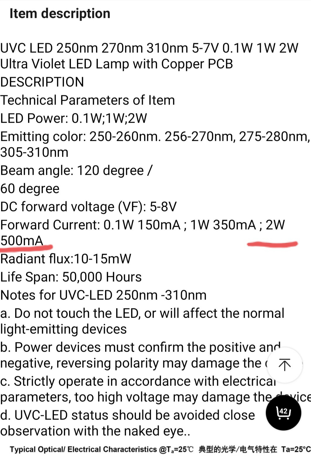
Could you tell me, what is the sense resistor doing exactly and how does it change with lower/higher resistance? The other comment in the Reddit Thread mentiones a R120 resistor for the 500mA. How is this calculated?
Furthermore:
My current plan is to swap the resistor, then put the LED on top of the brass insert. Should I use thermal paste or thermal pads? I also have thermal pad adhesive but the heat transfer is best with the paste, it is for CPUs anyway.
I would then solder the black/red leads to the LED PCB and put it back together with the plastic spacer. There are also some screws in the package, are these used to hold the LED PCB down onto the brass inlet?
After the resistor swap, can I test the driver? What happens, if I supply the driver with 3.7 volt input and leave black and red open? Will the driver try to put out 6V nevertheless?
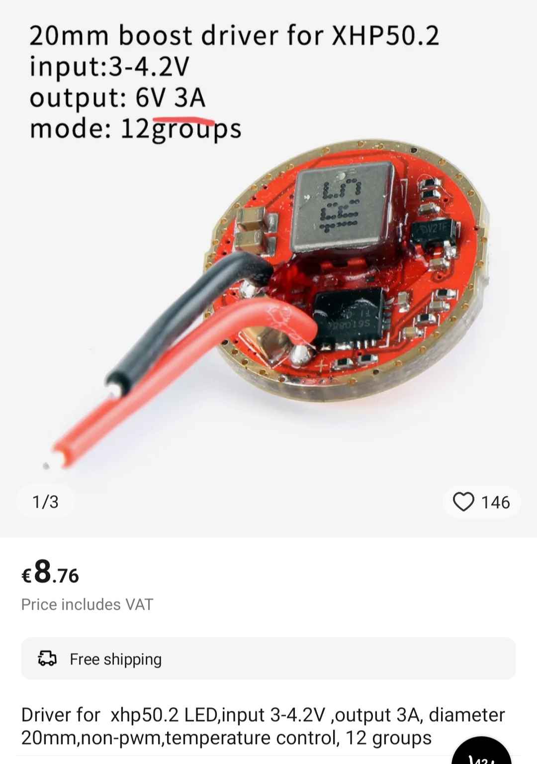
Hi there. Nice to see someone interested in building flashlights. I have no experience with UV flashlights but the principle id imagine is similar. You mentioned a convoy 6v 20mm driver. That sounds correct for the vf of your led. You will need a boost driver (it increases the battery voltage) if using one battery. Im not sure what specific driver you have, but Im guessing its for the XHP 50.2 led. These are desinged for high current and if that is the case, it may fry your 2W uv led.
I have guessed you chose the aforementioned driver. It is a 3a driver and your LED is rated for 500 mA. It will blow the emitter. I know swapping resistors on flashlight drivers will alter the current. I never heard of a “sense resistor”, unless for measuring the current.
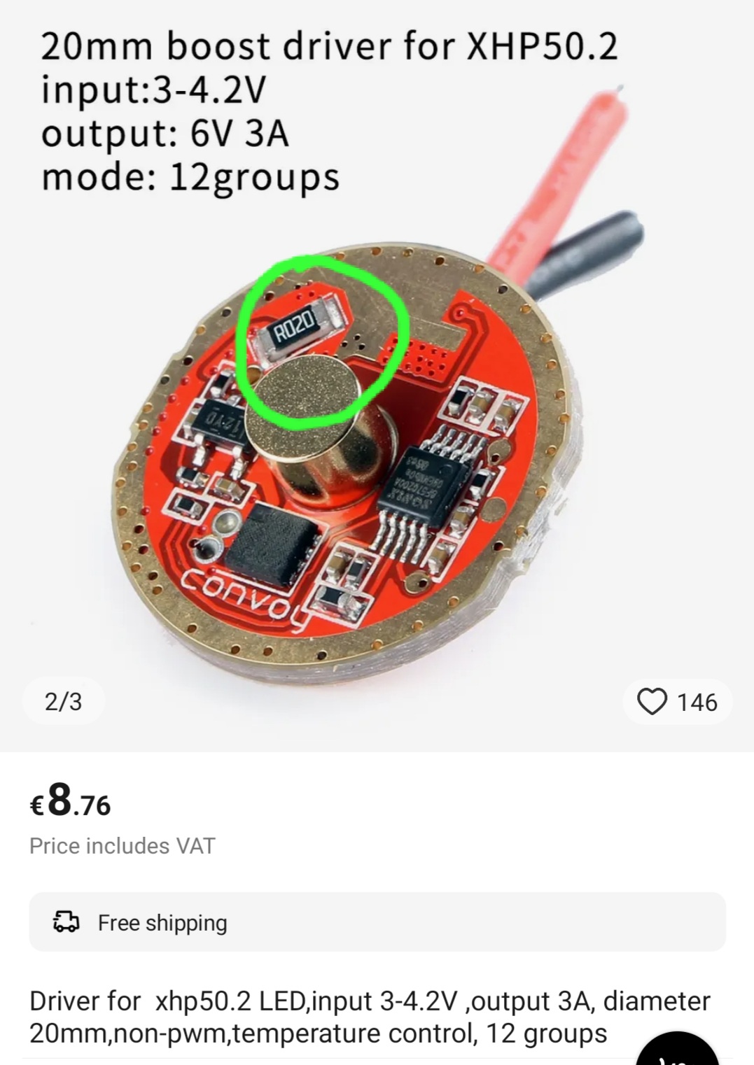
As seen from the specification sheet of the LED, its 500 mA and your driver puts out 3a, assuming that is it. I have circled in green the resistor I believe needs to be changed. Perhaps you might find a you tube video with the procedure. I have never done it myself but just trying to help. A higher resistance should decrease the current.
You mentioned thermal paste and screwing the MCPCB to the pill. I have used thermal paste for computers with no issues, and I believe that is what the screws are for.
You should be able to assemble the host and driver and battery without the led and the wires exposed to carry out measurements. Do not short. Voltage and current can be read with a multimeter. If the driver is a boost, it should read 6v or thereabouts with a 3.7 v battery. Hope this helps.
the driver is the one you posted, the 6V 3A driver. I already changed the resistor to a 120 ohm, as I found this number in a reddit post.
I made some pictures of the assembled flashlight, unfortunately the LED is quite dim:
If all 6V were across the sense resistor there would be no voltage across the LED.
You want to measure the voltage across the resistor in stock configuration on the LED it was designed for, or assume that it’s the design current of the driver flowing through it. Therefore if it were a 3A driver using a R020 resistor you’d get 0.06V across it. The driver attempts to maintain that voltage across it so if you increase it to an R120 resistor you’d get 500mA through it and therefore the LED.
You need special quartz glass lens, glass that is used in convoy, especially if it is AR coated will block uv, you will see visible light, but there will be no uv out the front. same way car windows blocks uv from sun. or remove glass completely. I’ve build about a dozen uv lights over the years so i’ve learned what not to do.
do not worry much about voltage resistors… just use boost driver with those leds if you ran it off 1 li ion cell. or run it off 2x 123a cells and use simple linear driver.
Just want to clarify that glass is fine for UVA but it does indeed block shorter wavelengths especially with its broad spectrum AR coat. Even ZWB2 glass isn’t that transparent at the extreme wavelengths, with ZWB3 being the best for around the 300nm range.