I have a zoomie I got a free as a learner light to tinker with. I finally have a reason to crack it open. The light runs on a single generic 26650-3.7v5000mah. The emitter specs can handle 6v 6a easily. Out of curiosity two Keeppower IMR18350 3.7v1200mah high were dropped in.
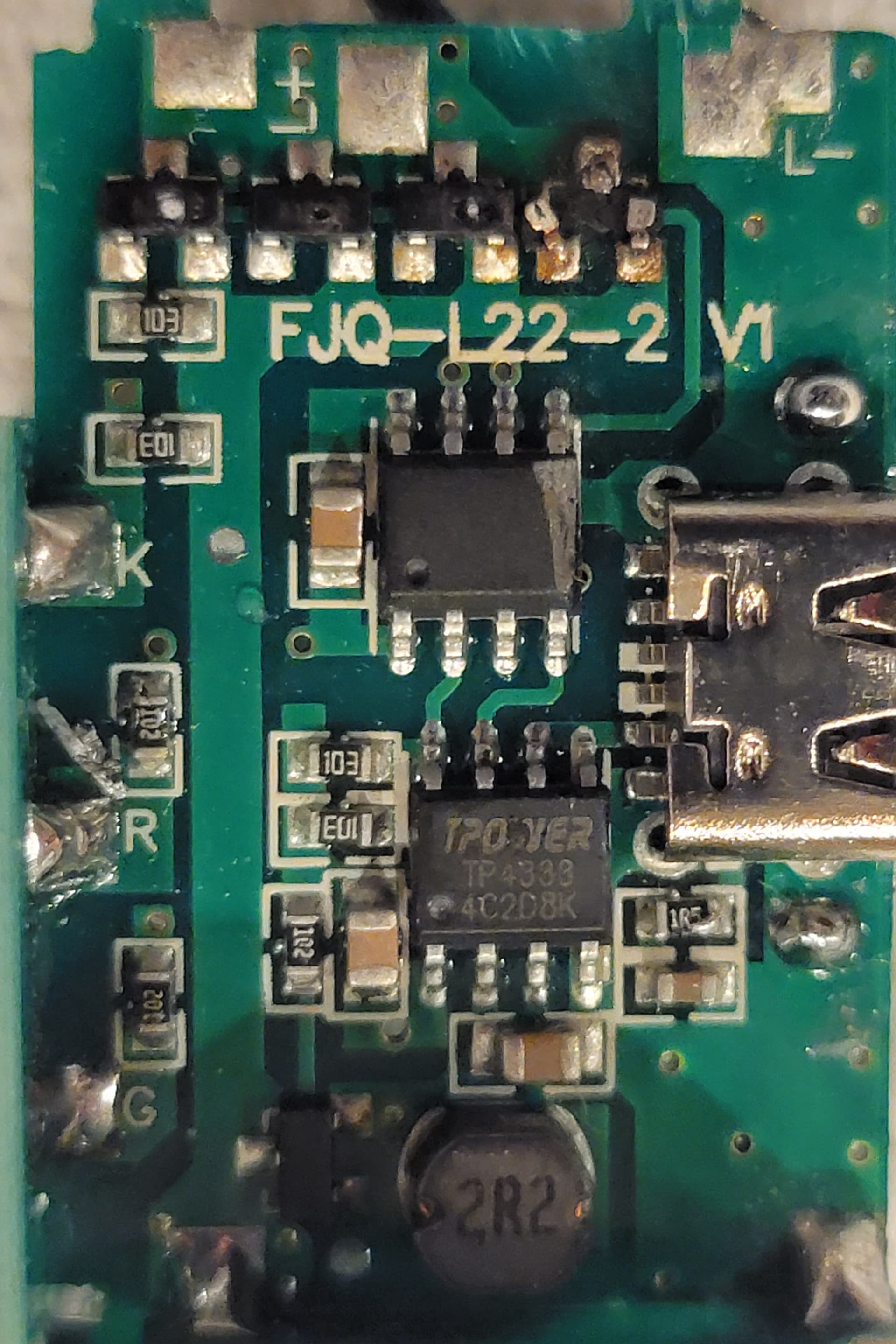
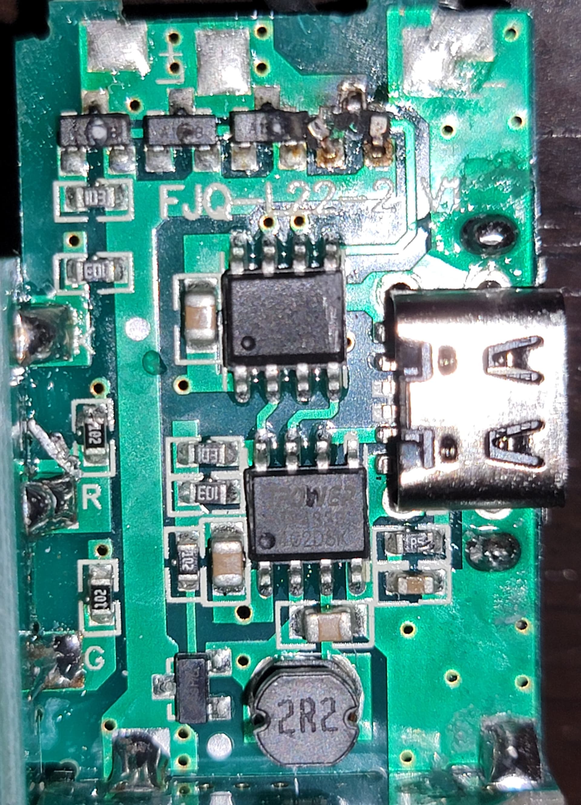
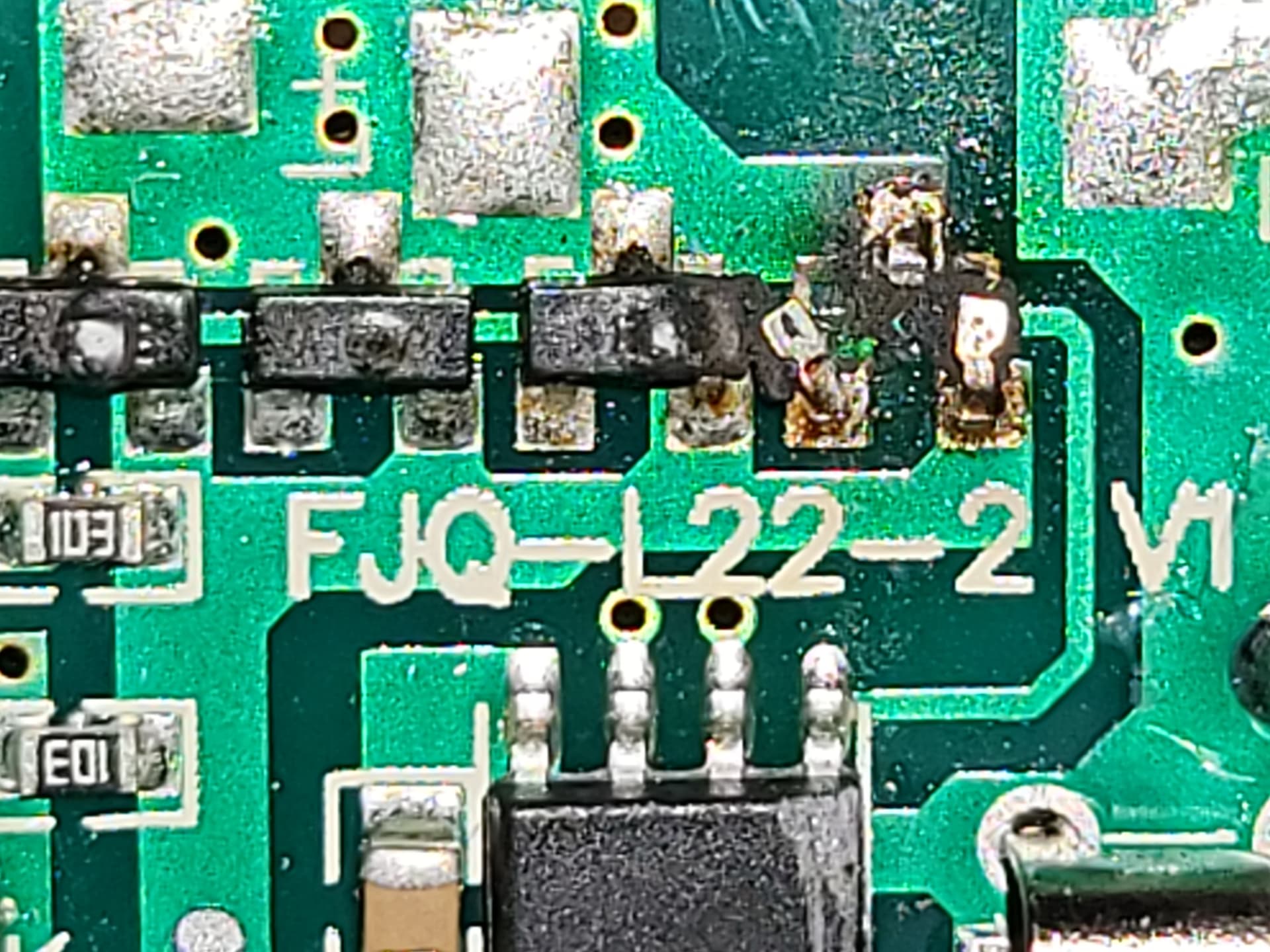
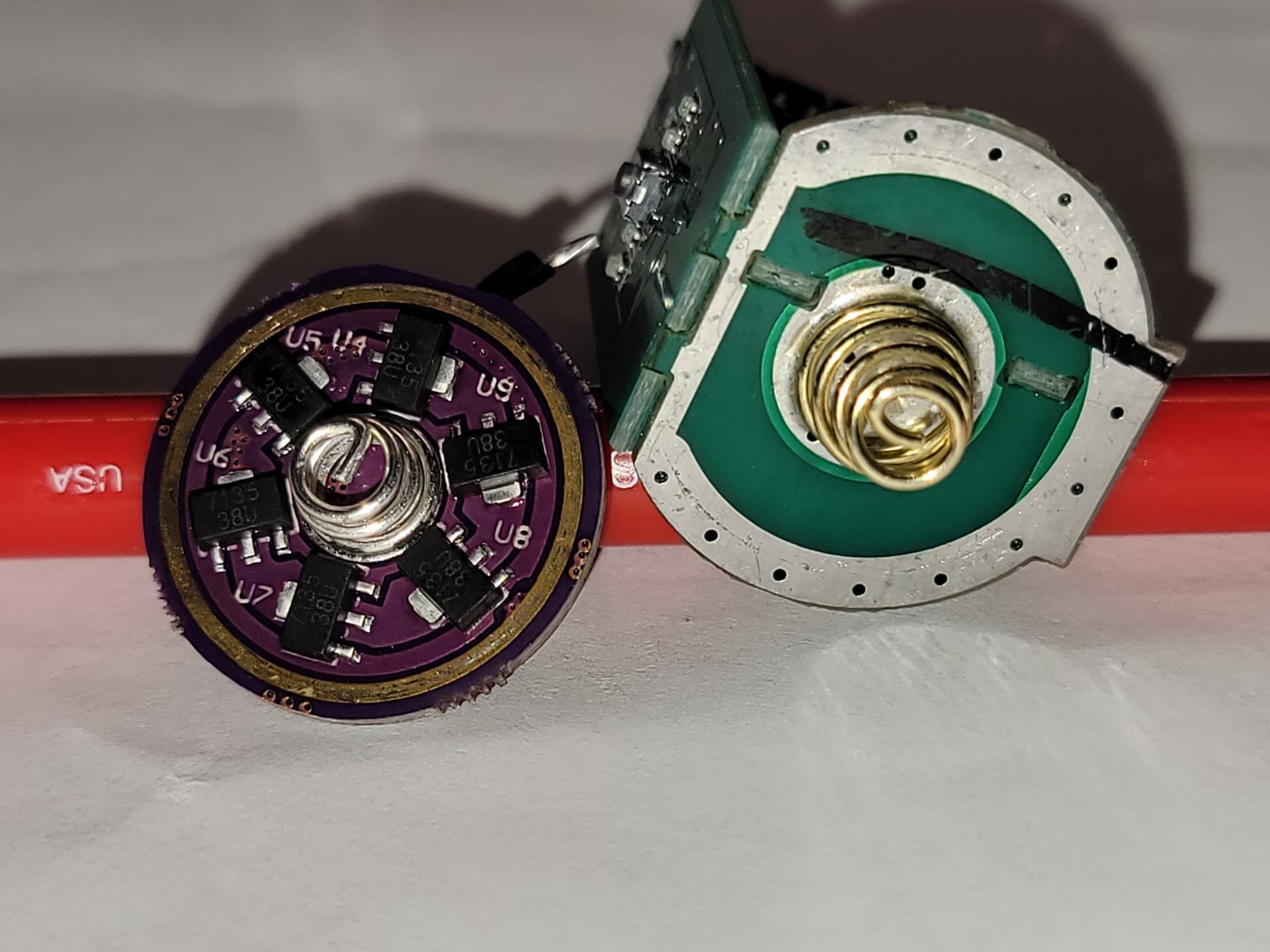
When the light was clicked on, it looked stronger for a moment before I caught the smell and when I opened it the smoke was definitely coming out, but the batteries were cool( See Pics below for carnage). It looks like a single chip evaporated (Is that 7135?).
If anybody could help me understand a little better what I am looking at I would appreciated it. I would like to take a crack at fixing it or swapping some components to allow it to handle the 6v 6a for an extended period.
What happened?
What did I do wrong?
Is this board repairable? If so what do I need?
Is there a driver I can swap in that can handle a constant 6v 6a load? This driver is22mmx28mm
Ya know that emitter may handle 6v but you fed it with 8.4v. An 18350 charged fully is about 4.2v. You used two of them in series. That’s 8.4v. The emitter, and as you figured out the hard way, the driver aren’t built for those types of voltages.
I don’t know if that is a 7135 or not but, if that is the only component that burned up then you can replace it and hope for the best. If you do get it fixed. Stick to single cells, not double. That driver board looks pretty some kind of crazy shape and size. Aren’t gonna find one like that. Hard to say without having the light in my hand if you could use a different driver. If so you are probably going to lose your onboard charging or whatever that connector is for.
All those 4 chips, whatever they were, are gone. Can be replaced, but you’ll need to figure out what they were and if anything else died too.
Emitter specs have nothing to do with batteries, what batteries can be used depends on driver (which then drives emitter as appropriate). If a driver was designed to run on 2.5-4.2v and you feed it 8.4v then yeah, all the magic smoke will be released…
Basically a driver is power supply for a LED. It takes whatever voltage is given and converts it into whatever voltage LED needs, also limiting current as needed. What you did - you basically took a power supply and fed it double the voltage it was designed for, with obvious results.
Yeah, drivers can be different, some basically connect the LED directly to the battery on maximum mode, but those are special cases where it works, with specifically chosen battery and LED. It’ll blow up too if you double the voltage…
If it were a 6V emitter with a single-cell battery, then it was a boost driver.
Almost certainly not one designed to run in a direct-drive manner like the dual-fuel AA/14500 boost drivers do.
Also, as mentioned, it was fed 8.4V - who knows how many amps at what voltage it turned into after voltage sag.
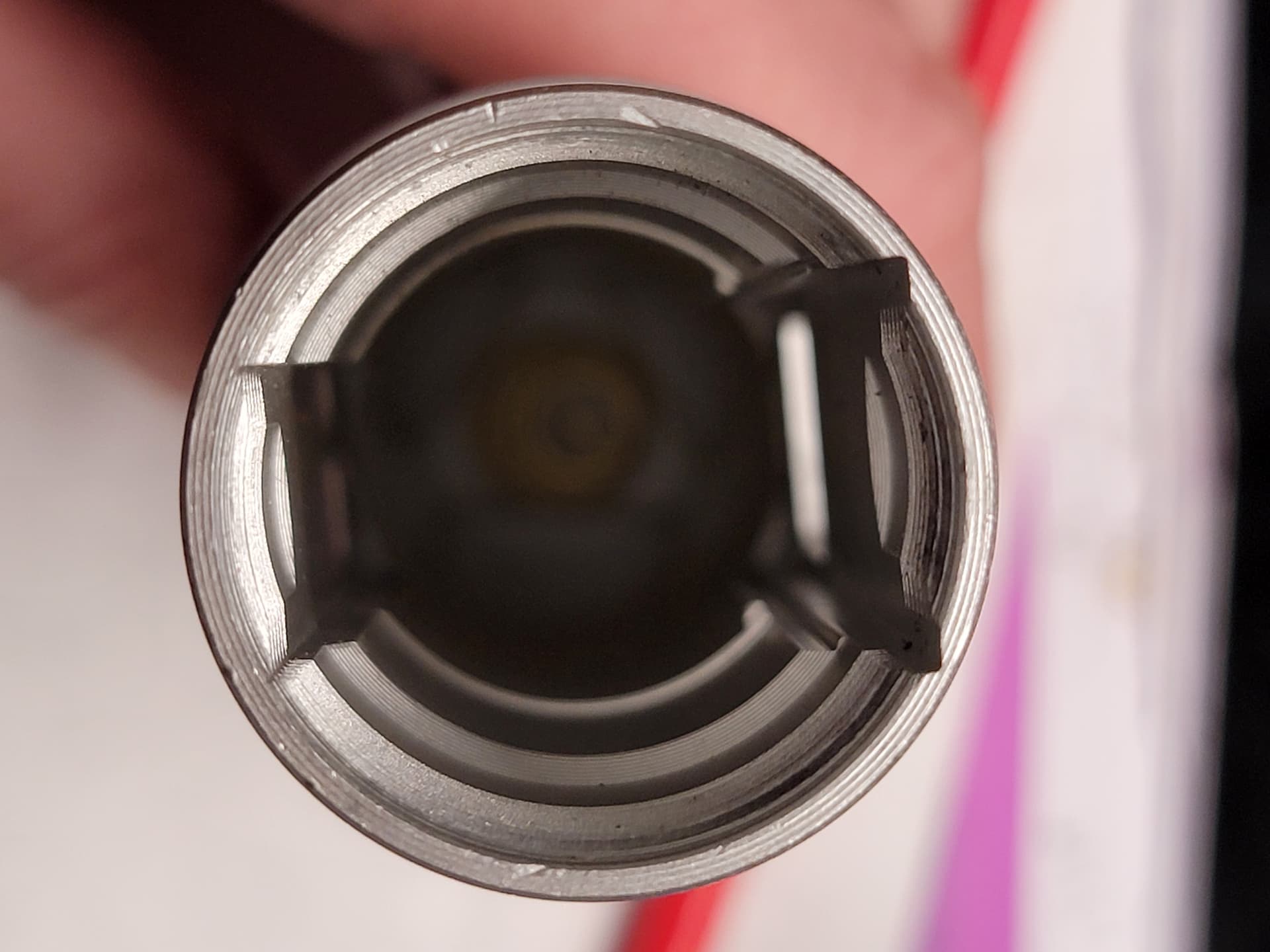
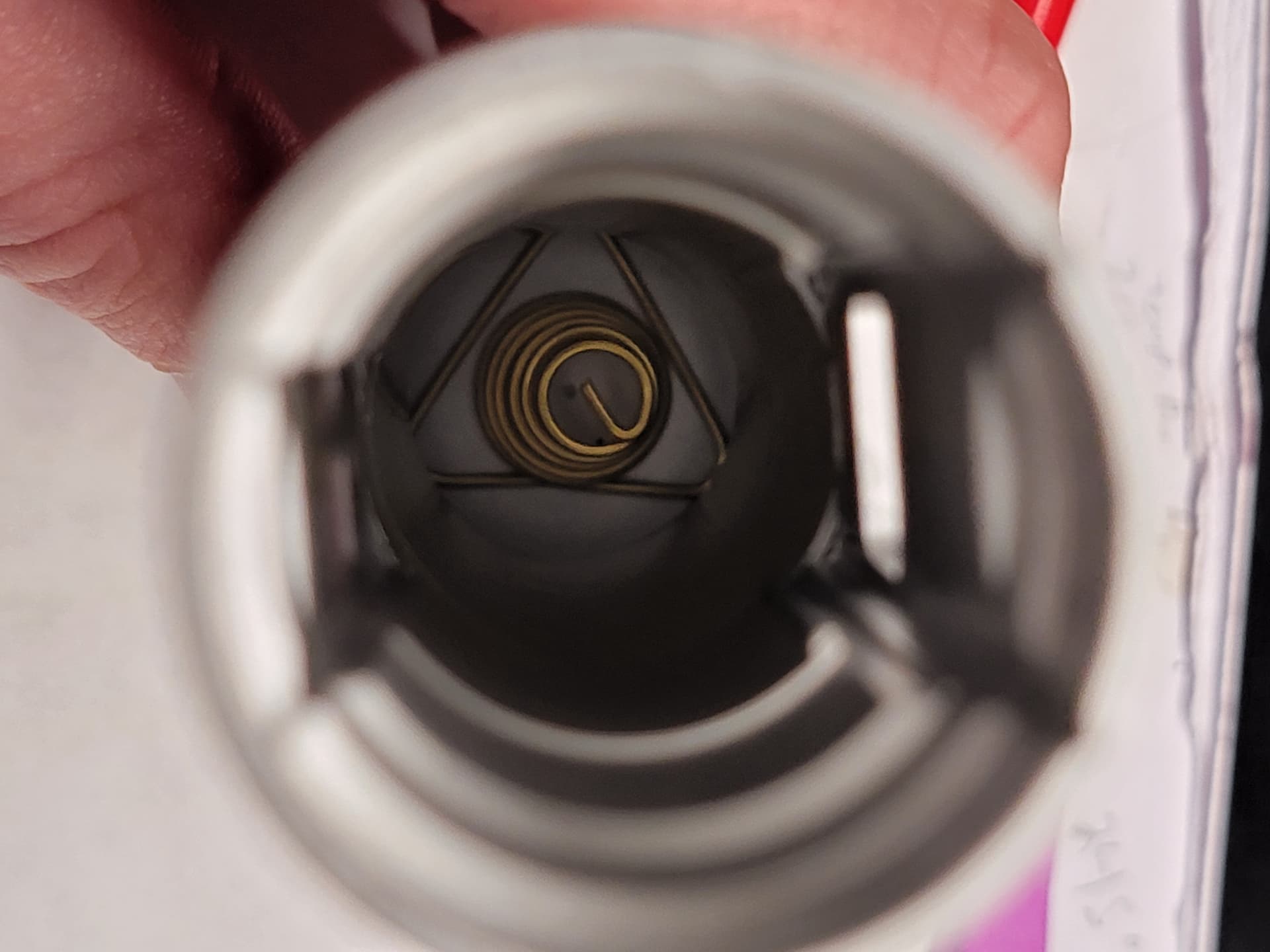
Thanks, Single cells it is. How can I find out what kind of chips those are? I don’t mind losing features. This light will probably end up being a frankenstein test mule. Here are some shots of the host. The cavity is huge. I could probably stack drivers and still have room , would that work? Here a some shots next to an FW3A driver measuring 21.5mm and the current driver 21x30x25mm.
How can I figure out what those 4 chips were? also ,is there a buck/boost driver that is can handle the 8.4v input and give a constant regulated high amp 6v?
The emitter looked happy at 5.6v *8A. Assuming a little voltage drop what is a battery driver combo that can drive this emitter at its peak for a while without over heating, reducing output or shutting off?
No marking no identification , but it is Pfets . 1 or 2 new good quality will do fine too. Its a simpliest PWM 1S circuit . Your led is 3V. No name chip MCU, another chip TP4333 and coil is for batt charging .
The pale red line with circles is the voltage graph for the Yinding. 5.6V will absolutely obliterate the poor thing. You are reading the lumen output line for both lumens and voltage. Its forward voltage for peak output as tested was ~4V at 8A.
Why though? What’s the advantage? It will not be brighter, that is limited by what the LED is getting (driver output), not driver input. And 2 cells give you less capacity…
Also that LED is 3v, and if you look at that graph it maxes out at around ~3.8-3.9V 6-7A. Anything more than that is simply destroying the LED.
They are SOTs so you need the right one, i think they come in standard sizes. This might be a SOT-23 but i am not sure what the designation is (eg SOT-23A/ SOT-23-3) buy one that matches your needs i guess, like above 5v and a few amps. You can always bend the legs to make them fit slightly or solder a bridge to each leg but i think they are a standardised size when you know the right prefix.