I seek advice on how to troubleshoot or repair a Convoy S2+ UV 365nm.
Can I test the driver board or do I need to replace it?
What happened leading up to the problem:
I disassembled and then reassembled the flashlight, and it no longer worked!
At that point, I had not disassembled the pill, but I may have used the dimples on the pill’s retaining ring to tighten the pill into the head.
I initially, at least partially, installed the battery in reverse polarity orientation, but I am not sure whether the tail switch was activated. The battery used was a protected NCR18650GA from IMRBatteries (it is red in color).
Since then, I have removed the retaining ring from the pill for troubleshooting, but have not cut or de-soldered any wires between the driver board and the led board.
Troubleshooting so far:
Checked and verified correct tube orientation between head and tail. (Yes, the non-anodized threads are matched between the tube and the head.)
Checked and verified tail switch functionality with multi-meter continuity testing.
Checked and verified continuity between tube and tail.
Checked and verified continuity between tube and head.
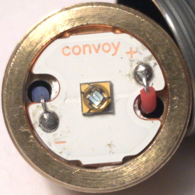
Checked and verified LED still works by directly connecting a Purple EFEST IMR14500 to + and - on the LED board.
Checked and verified LED still works by directly connecting a Purple EFEST IMR14500 to spring on bottom of driver board (+), and - on the LED board.
What are my next steps?
Is there anything else that I can test?
One thing that I noticed is that there is some metal on the edge of the driver board that is rubbed away or worn. Could this be the issue - could it have been done by my over-tightening of the retaining ring?
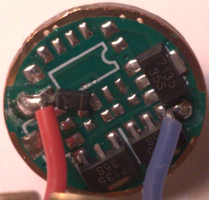
The photos don’t look very good but there’s not much to see it’s a pretty simple circuit.
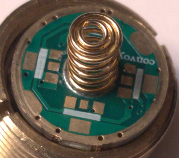
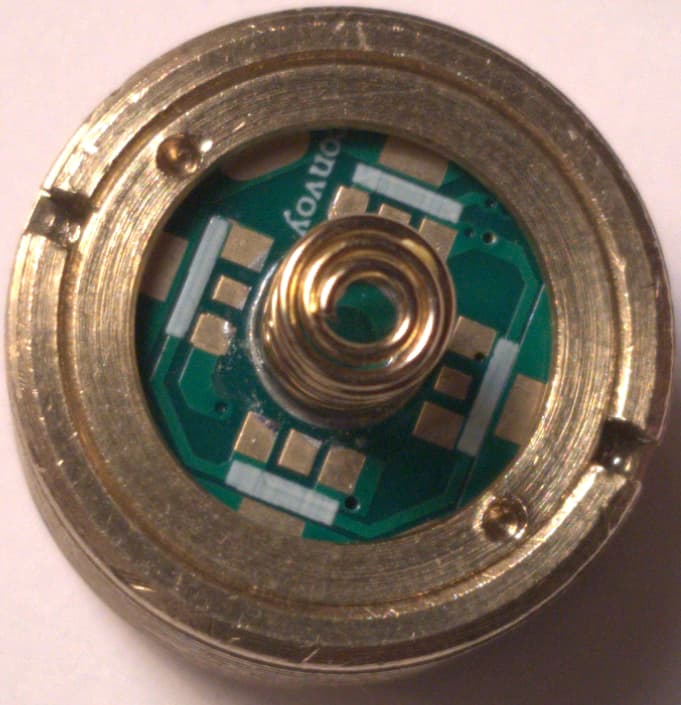
Try it unassembled with the battery, positive to the driver spring and negative with a wire to the copper edge where the tube would attach and see if it turns on.
If it does not turn on you have to check that diode if it only conducts in one direction, with a tester you can check it in diode mode.
And finally the mosfet just look.
Also if there is continuity in the masses between an outer ring the cut and the next but it is a plate that has the mass in another layer or so I think.
But it does not cost you anything to check it.
I repeat first with a cable you make a switch and tube and eliminate the problem is bad connection or that the ring short circuit the entire Drive as I see that covers much of the circuit if it is Mass nothing happens but if it is not there will be the puéblela.
Put less blurry pictures.
Edit:
The test if the clamping ring but you can leave the pill on so you don’t have to unsolder the led.
This is the best way to destroy the LED. The driver isn’t there just by accident. The components limit the current so that the LED doesn’t burn out immediately. Bypassing it allows “unlimited” current to flow (as much as the battery can handle) and UV LEDs are especially easy to damage with too high current. You can be lucky if it still works!
That can cause all kinds of failures. Maybe a short circuit somewhere near the reflector or the MCPCB. Assemble everything, check the resistance of the circuit. If it’s less than several kΩ there’s something wrong.
Depending on the driver design, this can damage it.
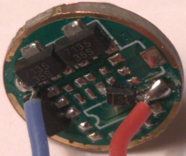
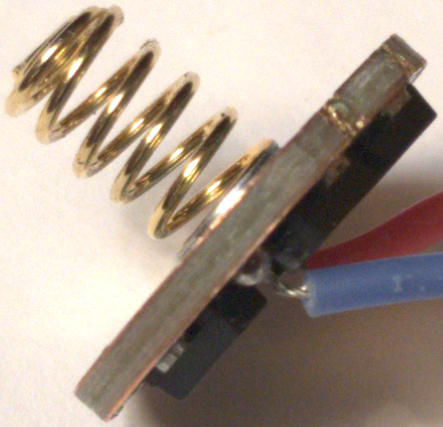
That diode looks out of place. I don’t know where it is supposed to sit, but it might be there for reverse polarity protection, got hot and desoldered itself.
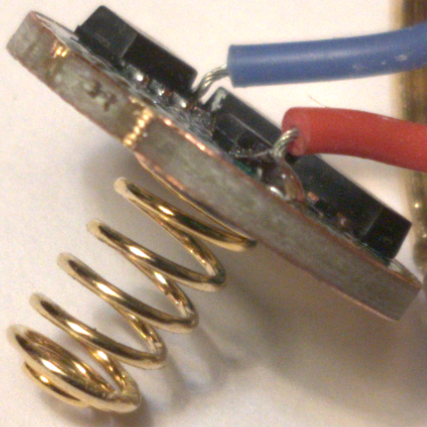
As seen in the last picture, the insulation of the negative wire is too short and the wire can touch the MCPCB. That should be fixed or it can cause a short.
[quote=“SammysHP, post:3, topic:218703”]
As seen in the last picture, the insulation of the negative wire is too short and the wire can touch the MCPCB. That should be fixed or it can cause a short.
Fix the insulation on that negative wire.
I think the diode position is correct.
Definitely fix that wire, but I don’t think that’s the problem. If that wire did short to the MCPCB, the LED would go into direct drive when turned on.
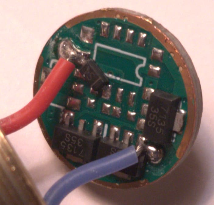
In pic #3, component S4 is out of place. It should be “vertical” (to the pic orientation). With respect to the red wire, it should be soldered between the pads directly right and top-right of it.
Hopefully nothing got fried and reinstalling that component will fix it.