I put together my first light with my 8 year old son tonight. Actually it’s going to be his light. First, I reflowed an XM-L2 to the MCPCB. It went fine, and testing it with my meter on the diode setting, it lit up like it should with positive and negative connections matching.
After soldering the DrJones H17Fx driver to it and completing the build, nothing happens when clicking the tailcap. I took it apart, desoldered the leads, and the LED still tests fine.
I resoldered the driver to the MCPCB and still the same. I tested the cap functionality with ohm meter. I tested continuity trough the driver. It was all fine.Ive used a few batteries ranging from 5 to 30A.
To eliminate the tailcap as an issue, i used a piece of copper to make contact with the negative side of the battery to the battery tube. It started smoking! The driver burnt up and the spring on the driver is even welded in a compressed state.
I tested the LED and it’s still working. I tried another driver (same type) with same results. No light. Can anyone give me an idea what I’m doing wrong? Thanks!
No idea as I’ve ran into the same problem with a few drivers from Mtn Electronics; thing just burns up. Been using Convoy drivers since then (both 7135 based and FET based) and never had an issue.
One lesson I’ve learned is that when you assemble and test a new light for a first time, ALWAYS use a protected battery, so that when a short happens the battery will cut off and prevent you from frying a $10+ driver.
Sounds like a short between the body and positive lead from the driver.
Is it possible one of the driver wires made contact with the bare copper where they come though the MCPCB? That can happen if too much bare wire is exposed or way too much solder is used.
You used a gasket between the reflector and MCPCB, right?
Did you accidentally damage the driver when installing the retaining ring?
Lastly, were the solder blobs too high and perhaps contacted the underside of the reflector?
Yeah, especially if using a dtp board, you gotta watch out for shorts, and insulate the f out of everything.
And best to use silicone wires and not “regular” wires, because with the latter, the insulation could pull back when soldering, and you end up with “bellbottoms” at the soldered ends.
Always use a gasket, or centering ring, between the reflector and the MCPCB.
Pay special attention to the soldering of the leads to the MCPCB.
If the solder “blob” on the MCPCB is too high, it can touch the reflector and cause a short.
You can stick a piece of kapton tape to the underside of the reflector.
I myself use a piece of strong thin plastic sheet that I cut to size (diam.20mm)
The sheet in the box separating two layers of chocolate is my favorite
When I build lights I ALWAYS test led/driver outside the light, before putting it all together. this way i know i’m installing a working driver/led, if I have issues after assembly then i know I did something wrong.
I’ve thought about trying liquid electrical tape on the underside of reflectors but haven’t tried it. I’ve been using more TIRs and triples/quads lately in my mods so it’s not something that I’ve worried about.
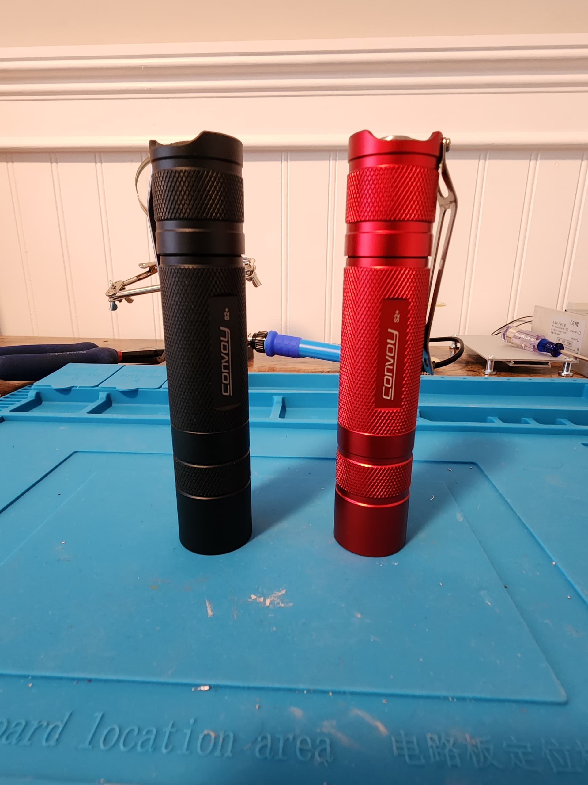
We have a happy ending. I built 2 S2+. The first driver is toast. After the second one wouldn’t toggle through the brightness settings and only output low, I installed the third driver. It worked fine! However, the driver didn’t fit snugly into the pill so I soldered it in. When I put it back together, it only went in low!!! I thought I had burned up all three drivers that I had.
It dawned on me to try going into configuration mode and see if it was somehow mode locked. It went into config and sure enough, somehow it was locked to a low output! It’s working fine.
The previous driver that was doing the same thig was also somehow in mode lock! No idea how they both got mode locked. Weird. But i have two completed lights, and I am very happy with them. Now, on to more!!! Can’t wait to learn more and put together many awesome lights!
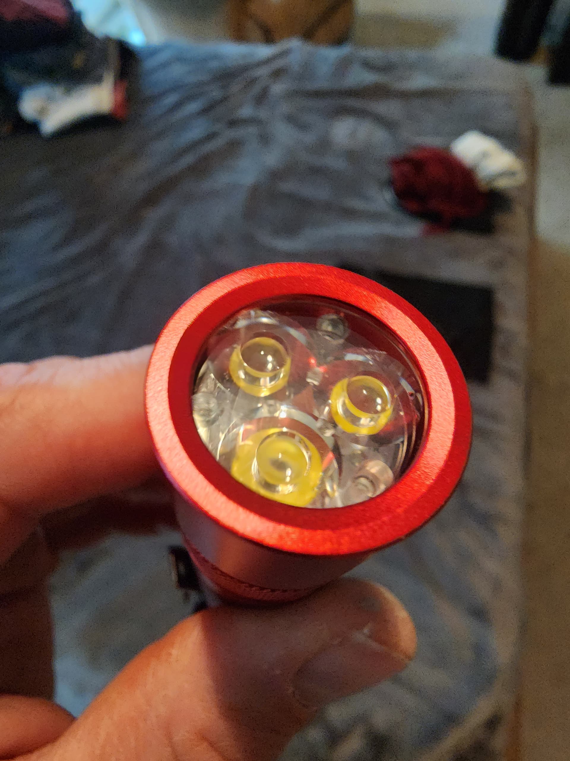
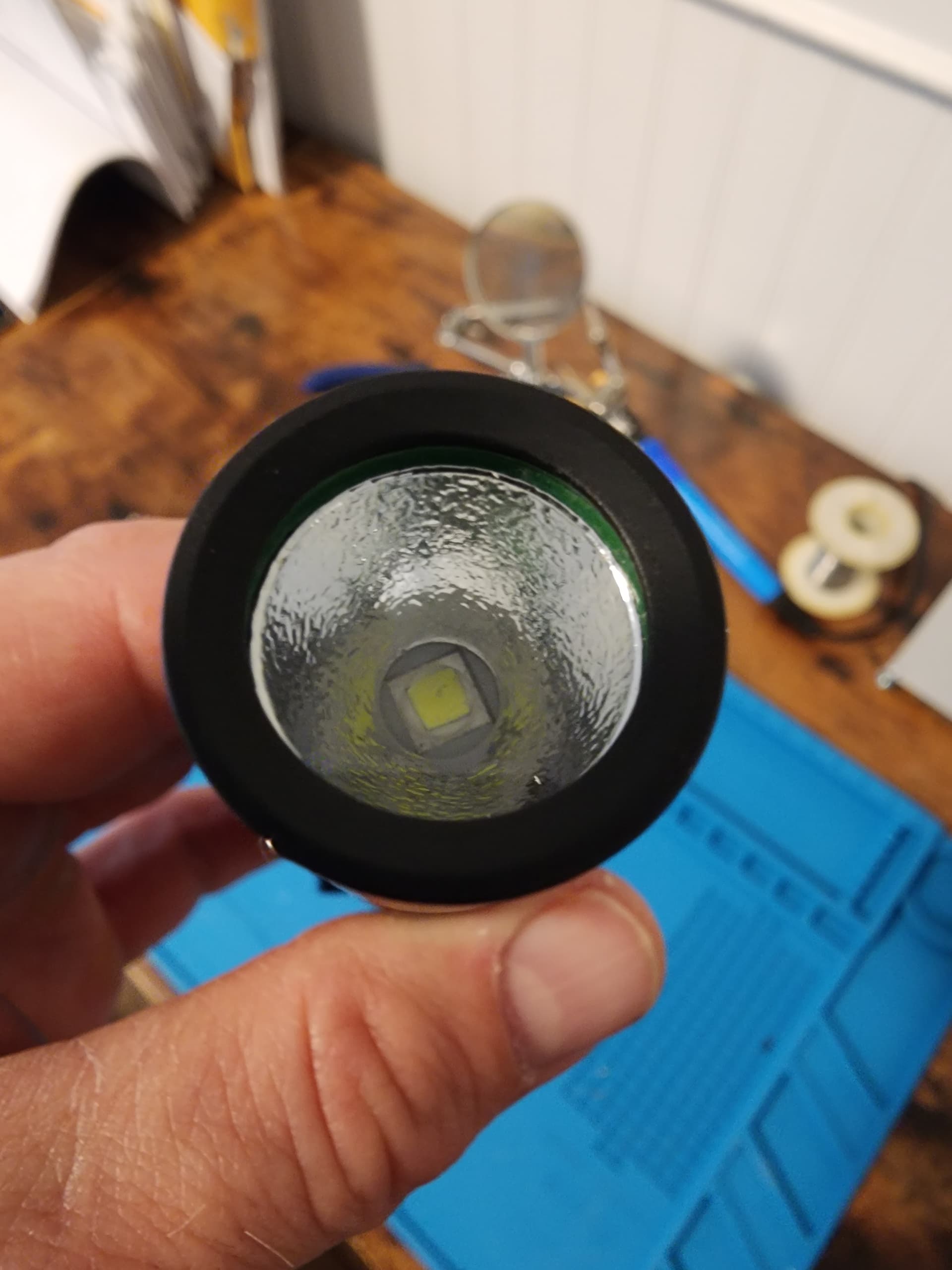
Black one is an XM-L2 6500k, red one is a triple XP-G3 5000k.
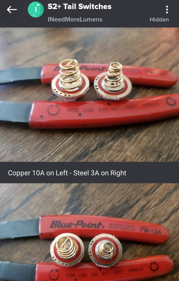
This has nothing to do with the issues you were experiencing, I highly recommend checking the tailswitch springs on your S2+.
The older ones came with a Gold plated steel spring which is only rated for 3Amps(Per Simon).
The newer ones come with a gold plated Copper spring which is rated for 10Amps(Per Simon).
These pictures might help you determine which spring you have. If not, you can test them with a magnet.
Good to hear! I hope you and your son had fun despite the frustration. I look forward to doing similar projects with my kids when they’re a little older.
Thanks for the info and the continued guidence and wisdom! I didnt know that. Mine look like the gold clad copper ones. However, I did bypass the springs on both of them with braided copper solder wick.
The last time I melted a spring was when there was a short circuit from the driver wire through the pill. The hole in the pill was too sharp and cut into the wire. I had forgotten to chamfer it. Many of the pills from the Convoy flashlights I’ve modified over the years have had very sharp holes.