I have seen this driver on KD.
I know FET drivers have no current limitation and AMC7135 drevers have x*350mA current limitatin
can you please explain how does this driver work?
Can I use PWM to reduce output?
If I use 2*A2SHB for one channel, will I get 3A?
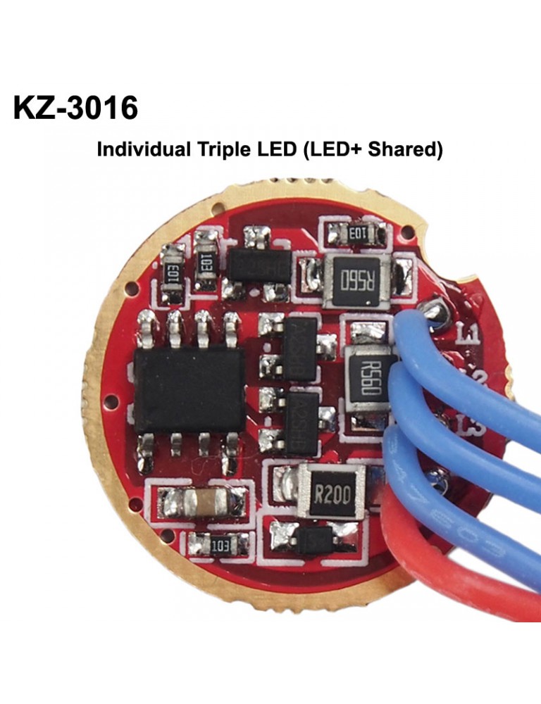
Looks like direct drive with series limiting resistors, not constant (1.5A) current contrary to what the description suggests. Would be dimmable with PWM.
Can you please explain what the mosfet is used for?
It is an amplifier; a small voltage signal on the gate can be used to control a large current thru the FET and the Load (LED).
It would be difficult to put 2 in parallel to get 3A because the current path is not unique and well defined—the current will take the path of least resistance which could be all thru one board due to timing differences, path resistance, component variability, etc. Countermeasures would need to be taken to insure equal current sharing in parallel circuits.
I planned to stack 2nd transistor on top of the one on the board not to use 2 boards, do you think it can work?
It might but i kinda doubt it. They are cheap so it won’t hurt to try.
One unknown is the power rating of the big current limiting resistors, but if you double the current from 1.5 to 3A, then the power quadruples.
Also it is not clear if the resistors are used to provide feedback to the ucontroller chip; some sort of feedback would be required to use PWM to regulate the current.
And as it is there would be a large voltage drop across the resistors at 3A that might not leave enough headroom for the forward bias to turn ON the LED. It would just be a heater circuit to drain batteries. ![]()
A “heater circuit to drain batteries” is not what I need