You could use the STAR off time memory firmware as a code example. It reads ADC for the off time capacitor.
STAR Firmware by JonnyC
Thanks for the fast answer!!
Sounds interesting, I’ll read a little more about this Firmware and how to edit it. H)
When I will succeed i’ll post here my results.
Not sure if I completely understand your question.
With nanjg 105c drivers power goes to the LED through the amc7135 chips. The LED is only on when the amc7135 is activated (high signal for LED full on or pwm signal for variable brightness LED modes). The attiny can turn off the LED but a 0 (zero) value pwm doesn’t seem to turn it off. You need to disable the pin entirely or pull it low.
The STAR firmware for momentary switches might serve as an example.
In the STAR firmware the attiny goes to sleep when “off”, attiny draws very little power asleep. An interrupt is needed to wake it up. Not sure if ADC can trigger an interrupt with attiny13.
Helios-, Thanks for your help!
Yep it should “”similar”” to my project.
My light will be in “always on” mode, as it won’t have any physical switch(clicky or etc.) - Just an NANJG star, LED, and an 18650 Battery (nothing else).
The only way to turn it on will be to put a magnet near the HallEffect, that will be connected to the ADC.
When ADC goes on high [ A magnet is near the HallEffect], I want the light to be on constant TURBO-HIGH mode.
When ADC goes on low [ no magnet near the HallEffect], I want the light to be off.
I will have to read the code deeper, in order to understand how to implement my idea, with this code.
When attiny is in “sleep-mode”, will it draw current from the battery?
In sleep mode the attiny does draw a tiny bit of current. There are different levels of sleep. Not sure how small the current draw is in the STAR sleep.
With flashlights, the current the driver draws when “off” / asleep is often called “parasitic drain” so you might see that term on BLF.
You could also just use a magnetic switch in place of the e-switch the momentary-switch firmware uses. That would allow you to activate it with a magnet and use the regular sleep mode since the switch would provide an interrupt. You also wouldn’t even have to change any code unless you wanted to change which modes the light has.
I have this type of magnetic switch in an ancient “Forever Flashlight”; simply get a magnet near it and the switch closes. Pull the magnet away and the switch opens. It was the solution they used to make the light waterproof; magnet on the outside of the dry area, switch on the inside.
@Helios- thanks ! ![]()
@ToyKeeper
I think that you mean using a reed switch, correct me if i’m wrong.
It will be a problem, because if I connect the switch between the battery and the driver, the high current will blow it.
After a small research I did I understood that those switches are built to be in low current environment, that’s why I should use the ADC to control the ON/OFF of the driver.
I just couldn’t understand something, I see that those firmwares have TURBO MODE and HIGH MODE, what is the difference? TURBO is 100% and HIGH is less?
I will have more time this weekend, I hope that I will be able to connect and flash everything ![]()
The emitter power does not go through the switch. The switch is simply used as a sensor, and the main power follows a completely different route. Don’t try to connect an electronic switch between the battery and driver.
If you were using a non-electronic switch like a traditional reverse clicky, then yes. The emitter current would need to go through the switch. But not for an electronic switch.
What does the signal coming out of the HALL sensor look like? Is a a single “blip” when activated, a constant (or PWM) output or variable or what?
The output of the Hall effect is “Linear voltage output” which goes high/low and depends on magnets proximity.
Taken from the DATASHEET [ LINK: Safety and Productivity Solutions | Honeywell ]
I hope the ATtinys’ pins will be able to sense those outputs.
ToyKeeper was saying a magnetic reed switch could work as a simple replacement for the momentary tactile switch used in the STAR momentary firmware. If attiny13 can’t do ADC interrupts then a linear voltage output hall effect sensor won’t be able to wake the attiny from sleep. In that case a reed switch could be used instead.
Oh…… Only now I got it.
Sorry for my ignorance.
I thought that the switch in STARs’ firmware is a regular switch.
Now that I read a little more about it, I saw that you should connect the “e-switch” to GND and STAR4.
Now it makes sense, and changes the picture to me.
Do you know to what pin on the ATtiny this STAR4 goes on the NANJG board?
That way, I think, that I will be able to change the values it reads from the this STAR4 , and change it in according to the hall effect.
:nerd_face:
I have this little diagram at the top of my firmware so I don't forget...
/*
 * NANJG 105C Diagram
 *           ---
 *         -|   |- VCC
 *  Star 4 -|   |- Voltage ADC
 *  Star 3 -|   |- PWM
 *     GND -|   |- Star 2
* ---Pin 3 HOWEVER the MCU isnt reading a voltage from the switch, the momentary switch is simply providing a path to ground when pressed.
The STAR momentary code definitely wont work and I’m not even sure code could be written to work, I dont know enough about the attiny13A to know if it can read a positive voltage input there or not.
You could possible use some other sort of magnetic switch that would provide a path to ground to work with STAR-MOM but not a hall sensor, its all wrong for what STAR uses for the input.
Hi all and thanks for the replies!
About the hall effect, i think that is possible to provide a path from the ground to pin3 with it.
I have seen some diagrams of hall effects and I think that its’ output is negative (as ground)
For example this diagram: https://www.kjmagnetics.com/images/blog/wiring_hall2a1.png
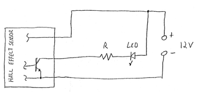
What do you think, should it work that way?
Well that looks promising, any idea the length of ground pulse it puts out? Probably need a resistor in line to make it usable but I don’t see why not, I was thinking the hall sensor put out a + voltage signal.
I hope it’ll work as well, haha
Tomorrow I’ll have more time sitting on the software and soldering everything.
I tried searching in the Datasheet, but couldn’t find any information about that. is there any other way I can check it?
Thanks!
got a sound card oscillascope?
Nope, but waving a thin stiff white sheet through the beam provides a reasonable approximation, at least for measuring PWM. I can see the 19 kHz PWM on my XinTD C8 V4 that way, and can get a rough estimate of the frequency. By adding a camera, I can even measure the duty cycle.
Hi to All!!
I have some good news, and some bad news.
The good news are that I successfully burned a momentary firmware on the ATtiny, based on ” MiniMo - DrJones” with my modifications, as I need it only with one mode [100%].
And connected the hall effects’ output to STAR4.
The code looks as that:
The temporary station looks like that:
[2 pictures]

AND IT WORKS!
Here is the video:
Now, the bad news are, that my DMM shows only 1.06A output (with fresh battery and 8x7135), have no idea why.
maybe the software.
What do you think?
Another thing, what is that TURBO mode that I saw on some firmwares?
![]()