Would you have some realistic set of values for a few flashlights with reflectors (can be a mixture of smooth and OP) for which you know reflector height and width (or the spill divergence angle: atan(D/2h)) along with the some realistic estimate of the beam divergence angle (FWHM?) and the ratio of cd/lm in the centre?
I have a few ideas that I would like to test on some external measurements to see if they make sense.
You’d probably have to take some integral of the reflective surface in relation to the LED emission angles, then approximate using a target surface. The thing is, alot of the “rays” are going to intersect at least once in a cross section, and makes overlapping/offset circles on a 3d model. The area which overlaps the most becomes the hotspot.
**to help clear up any confusion in the concept, remember the old incan maglites? The focal point changes according to the depth of the bulb within the reflector. It makes different shaped hotspots depending on where the rays converge the most. At the optimal focus, the hotspot becomes a spot, because that’s where the most rays converge on.
The fraction of lumens from idealized lambertian LED that is reflected and feeds the beam seems to be:
1/(1+D²/4h²)
D and h being the reflector diameter and height.
The beam (spot) divergence angle itself is more complicated, one could try incorporating the LED size, but I figured that if the spot radial intensity is about Gaussian and the the spot cutoff point is FWHM, that could be roughly estimated in degrees by knowing sqrt of cd/lm ratio in the centre as:
≈54/√(cd/lm) times the fraction above (I think…)
So for instance, my T6-SFT25R has √(cd/lm)≈6, and D/h ratio not far from 1, giving the approx beam divergence angle of some 6°, which given the uncertainties in the method looks not too far off.
The beam divergence being a total of 6 degrees, or total 12 degrees? My brain is kind of fried right now, so I’m drawing blanks on just about every term lol…
Like 6 degrees from the center of the beam to the radius, or 6 degrees across the diameter of the hotspot?
Unfortunately, I don’t have reliable measurements for the hotspot angle–this can only be done over sufficiently long distances, and if the boundary of the hotspot is well-defined. The latter presents great difficulty as (1) most emitters are not circular, with no orientation-invariant “diameter” to speak of, and (2) most reflectors I have are slightly misshapen, enough to throw off these calculations substantially.
May not make a difference but just want to point out the brightness (lumen) numbers are @ 0 second (because most companies are using this), whereas the throw is ANSI, at 30 secs.
Sorry I haven’t followed this conversation closely but are you saying square root of cd/lm is better predictor than cd/lm?
Not an expert nor a mathematician, but I first look at Koef’s luminance to see thrower vs flooder LED, and then type + size of reflector to see thrower vs flooder lights (host + LED). This is the cd/lm number I guess. In addition I’ve noticed a rule of thumb, big candela with small lumen values (below ~ 1500 lm) means invariably a thrower with a tiny hotspot.
It’s just the scale that differs - easier to judge the differences (for me). Both metrics are independent of lumens.
Your lights are a great example: it’s hard to tell if they are any different by scanning the range and lumens pairs, but based on the ratio alone I picked 2 that should be more similar than the other 3.
Also easier to rank their beams relative to the range of lights I have - e. g. the two should a bit more floody than T6-SFT25R or not far off from IF19, while the other 3 should be close to to HS21 Spot (TIR/reflector spill pattern differences notwithstanding), or nearly half as ‘throwy’ given the same lumens.
That’s my prediction, but is it what you really see?
On a related topic of comparison - square root or not, I think. I’ve noted something interesting, as far as throw numbers: 100 m = 2500 cd 200 m = 10000 cd
Expressing throw in meter, one light throws twice as far. Whereas expressing in candela, the throw is 4x “larger”, widening the perceived throw gap between two lights. So which one expresses the relationship “better”?
For people like me (not mcjtom), why the gap narrows: Throw distance = square root of (candela x 4). I think!
It’s a little bit like megapixels in camera sensors. If one ignores all other things (such as physically smaller ‘pixels’ being more noisy), a 20Mp sensor has higher line resolution than 10Mp sensor, but hardly twice as much - for that you would need to about quadruple the megapixels. Square root of Mp would work better to compare the linear resolution of sensors, but it is not used.
Maybe not the best analogy, but imagine a wall with a square checker board of 1000×1000 alternating black and white squares. So 1 mln squares. You stand 10 m away from it to take perfectly-aligned picture on a 500×500 matrix (¼ million Mp). The image should be all perfectly mid gray because each sensor pixel averages 4 checkerboard squares - 2 white and 2 black. You can’t resolve the checkerboard pattern.
So you must increase the number of megapixels that your matrix has, but by how much? If you double the Mp of the matrix to 0.5 Mp (some weird 707×707 pixels sensor), you may start seeing some texture but still not enough to capture the checkerboard pattern. Quadrupling it to 1 mln pixels will resolve the checkerboard.
In a similar vein, if your ¼ Mp camera at 10 m from the wall gives you perfectly gray image (no resolution of the checkerboard), bringing it to 5 m (half the initial distance, not quarter) will capture ¼ of the checkerboard area (250000 or ¼ Mp checkerboard squares) but now they are perfectly captured/resolved.
I just want to add that I think that the best measure of the flashlight inherent throwiness tendencies - which accounts for LED+optics combination but doesn’t care how hard you drive the light may be:
Beam Acuity ≈ √(π×cd/lm)
It’s the property of the flashlight, not how bright you make it.
It has nice properties:
it gives 1 for the floodiest of flashlights - a bare lambertian or a mule
it produces 0.5 as the lowest limit of any light - omnidirectional naked bulb
it is proportional to range - given the same lumens the light with twice the Beam Acuity will throw twice as far no matter how the range is defined (ANSI terminal cutoff is ¼ lux, I prefer 1 lux which is simply √cd or ½ ANSI range).
it is also proportional to the beam divergence flat angles and hotspot diameter - we are not intuitively compatible with solid angles in steradians and comparing areas.
It’s likely about proportional to our perception of brightness - a target at fixed distance should look nearly twice as bright when illuminated with a flashlight with double the Beam Acuity, given the same lumens.
the scale values are in a moderate range that goes from 1 (or 0.5 but that’s not a flashlight) to some 50’s for LEPs and it’s easy to interpret (as above). Also a granularity of ±1 or lower is probably sufficient and smaller than the uncertainties of lm and cd measurements used to construct it - no need for decimals.
Start in the bunker.
This is one of four videos that Martin put out showing multiple flashlights per video in the same location under the same conditions. Of course these videos are 5 years old now so most of these flashlights are not currently available. Remember these are in pitch dark conditions. Turn on a light nearby or add a little bit of background sunlight and results are going to be dramatically different. I’ll add more thoughts later.
Awesome, thank you. Just spotted an LEP in the VDO - like a pointer - and on the proposed Throw PotentialBeam Acuity scale it scores near 100. This makes the scale quite intuitive: 1 for a mule, ~100 for LEP pointers.
The tests and the commentary are great, but the range and lumen values seem to be taken from the specs and look inflated. I’m not sure if for both metrics or just lumens and for which lights. If for both equally, the ratio may stay the same, but I don’t know.
I right away saw “complication” when I started this experiment. First and foremost is the definition of being"spotty" - it’s subjective. So ranking is based on my own and VERY subjective (YMMV) perception of being spotty, at least from white walling 6 meters away. Factors considered:
How bright the hotspot.
How small the hotspot
And… the surprise and “problem”, how bright the spill. A bright spill makes the beam less spotty.
I will use score 3, 4, 5, 5 being most throwy, so it matches your numerical numbers: 3.5, 5, 4.5, 4, 3.5.
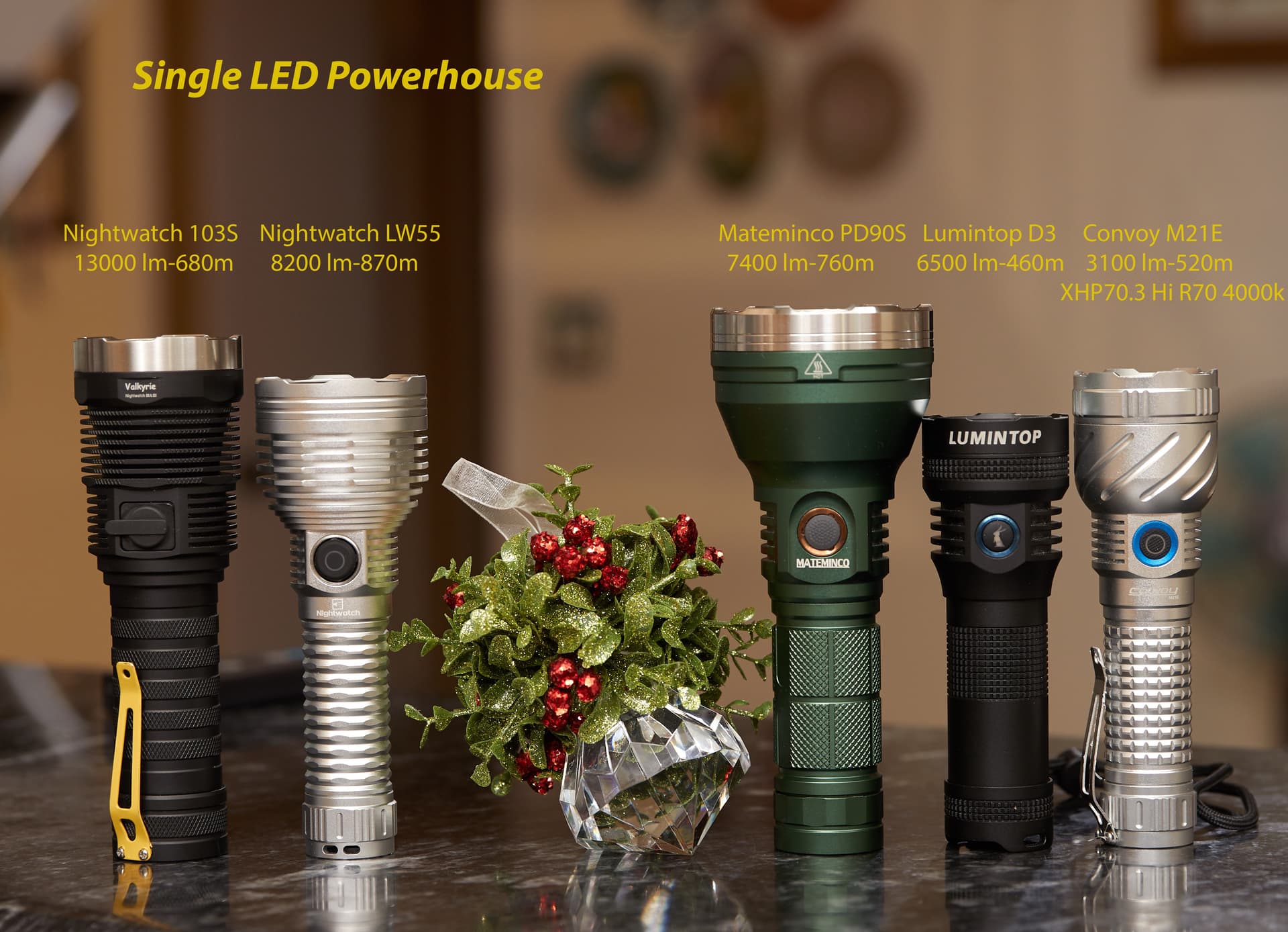
Nightwatch LW55 has the brightest, smallest hotspot, and a dim spill, making it the most spotty/throwy beam. M21E with XHP70.3 has subjectively the brightest spill, contributing to the lower spotty ranking.
One big problem is there are so many variables. Math isn’t going to get you there. I spent some time yesterday trying to come up with a reasonable distance to be able to measure a “hotspot” from a white wall or piece of cardboard.
1 ft/30cm or double that. 1 foot works pretty good for lights with a pretty tight “hotspot”. As already mentioned multiple times, what percent of the total light output is in that “hotspot” versus in the immediate spill versus the widest part of the spill.
Trying to measure the width of the spill is very difficult. Reflectors do tend to have a fairly well-defined cutoff. Not so much with a “tir” . And there are so many different variations of "tir"s. Just saying TIR means nothing about what the beam shape is going to be.
Hot spots are not always well defined. How floody is floody.
Many new people come along and plenty of old people here and say they want or like a beam with some “throw” and “usable spill”. Again how do we define this. Is that “spill” bright enough to light the ground 3 ft in front of us as we’re walking with the light pointing straight ahead at waist height. Or is it 8 ft or 12 ft in front of us?
I know I want my headlight to provide plenty of usable spill way out to the edges. And I want those edges to be wide. And I’m not really calling it spill because I don’t want to see a hotspot. Not all headlights that produce a “floody” beam create the same amount of flood. We don’t have a good way to measure that.