Agree with the problem of too many variables, but math is the only way to make sense of it all.
Quantifying a beam shape, in essence, is trying to describe an arbitrary probability distribution on the sphere (or, assuming radially symmetric beam, a distribution on the angle space [0,180]), with as few numbers as possible.
This is mathematically impossible because the space of distributions is infinite-dimensional, but with some natural smoothness assumptions one can still come up with a small list of numbers (e.g., maximum, variance) that approximately describe the distribution pretty well.
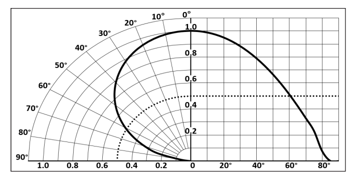
Alternatively, one could simply generate an angular distribution plot, which is found in every LED datasheet:
What are some parameters that determine how long a distance this needs to be? eg Does large reflector take a longer distance than small reflector to collimate into their final shape? Large vs small LED? etc.
And how is a fully collimated beam shot look different from a not-yet collimated one? Brighter? More focused with tighter hotspot? TIA
Larger reflectors and smaller emitters both delay collimation of the beam. The metric cd/lm captures the dependence on both reflector and emitter size: the greater the cd/lm, the more distance you need.
In general this is hard to tell from a single photo. I can tell a beam is fully collimated if the beam profile doesn’t change when I double the target distance–note that this requires 2 photos/observations!
But there are factors that let you know for sure that a beam is not collimated. Examples include a donut hole in the center (that goes away with distance) and no clear corona visible in a reflector light.
Sadly, the problem is rather open-ended and ill-formulated, though it would be an interesting mathematical problem to even formulate it precisely.
One might argue that is already has a partial solution: it is known that distributions with bounded support (which the angular distribution is) are uniquely characterized by their moments (mean, variance, 3rd moment, etc.), which gives you a countably-long list of numbers, in decreasing importance, that describe the distribution perfectly. One can get good approximations via truncation of the list.
Would two different optics/reflectors, with the exact same proportions, perfectly scaled up or down, maintaining the proportional distances to the emitter, project drastically different beams?
(For all intents and purposes, it would be an inefficient and wasteful exercise if they actually produce near identical beams, but it could give some insight as to minimum required dimensions for beam shaping. Naturally, I’d expect someone else to take all the credit for these revelations. forever the brain, never the hands.)
Just to check my understanding: you have 2 reflectors that are dilated copies of each other, focusing the same emitter. In this case, yes: the larger reflector will project a tighter beam.
Think of it this way: imagine you’re at the receiving end of the beam. With the same emitter, the brightness you observe is proportional to the size of the bright object you’re looking at, i.e., the frontal area of the reflector. The larger reflector has a larger frontal area, so you receive more intensity.
Since the emitter (and thus total flux) is the same (and roughly interpretable as the product of beam intensity and beam coverage), a more intense beam must necessarily be narrower.
It’s true that the definition of spottiness or acuity of the beam using cd/lm or functions of it may be a little fuzzy if you treat it as describing the beam divergence directly.
This is because, hypothetically, with the lumens fixed, two beams with equal cd/lm don’t have to be the same: one can be a little wider but stealing more light from the spill, the other a little more concentrated but with more light going into the spill.
But there is a saving grace: spills don’t have that much light to steal from and also decreasing the beam divergence angle a little increases its intensity as a square of it, so that’s more efficient than diverting spill into a beam.
Take T6 for instance. The spill cone half angle is maybe 25°. If you integrate the LED output over the corresponding solid angle you will end up with sin²(25°) or less than 20% of total lumens being in the spill - the rest or over 80% (cos²(25°)) feeding the beam.
Even if you magically divert all the spill light into the beam without touching the beam shape, the beam won’t be much more intense (cd should increase ~25%). Tightening the beam angle slightly should accomplish the same thing.
So I think that cd/lm, especially in the form of √(π×cd/lm), is a decent descriptor of beam acuity and should comparatively correlate well enough with things like beam divergence, spot size, and terminal illumination capacity, while separating beam properties from the amount of light supplied.
I did a little more testing. I have four different convoy S2+ with four different LEDs . They all have the same smooth reflector. They all have different sized hotspots.
Way too many variables.
The one I chose to do some measuring with had the same sized hotspot at one foot from the wall as a s21e with a sft40. The hotspot measured approximately 2 inches with the lights 1 foot from the wall with both.
The spot was approximately 23 inches with the lights 11 ft from the wall with both lights. I picked the 11 ft just because the spot fit nicely at that distance between a door frame and the corner of the wall.
I had AI do the math and it worked out to approximately 9.5° (1 foot), and 9.8°(11 foot).
I’d say that’s within the margin of error of trying to measure the edges of these hot spots when at both distances.
I did the same distance measurements with a GT mini with a 43 mm bezel, XP-L HI. It has a very tight spot. Approximately 2 inches from 1 foot away (9.5°). Approximately 8 inch spot from 11 ft. Approximately 4.8°.
There is a pretty wide Corona that was about 23 inches. So it might not be fully collimated at one of those distances. I’ll have to do some outside testing in the dark in the coming nights. I’ll probably try to aim for 100 ft.
Let’s see if I’m understanding correctly…assuming that it’s like holding “SHIFT” when perfectly scaling up an object, such that even the proportion of even curvature and emission angles all stay exactly the same, in addition to the hole size for the LED getting bigger…the apparent image being reflected/projected will shrink because of the increased proportion reflecting surface area in relation to the emitter?
I.e., Let’s start with an ideal hypothetical and work our way to practical LED’s…Assuming an ideal point emitting source, and a basic perfect hemisphere were designed such that it would reflected all the light beyond a 90 degree arc, or 45 degrees from the center, then would perfectly scaling it up drastically change the beam pattern **and absolute intensity?
Next, what would perfect scaling do to exponential/parabolic curves?
And since LEDs are NOT ideal point sources, they rely heavily on surface intensity of their outermost apparent emission surface…at what point would scaling up the reflector start to yield minimal gains in throw?
When you scale up an object, the curvature must decrease, since for a circular arc, curvature is simply defined as the reciprocal of radius, which gets scaled up. But to clarify again: if you dilated/scaled the whole reflector up, the projected image shrinks. One can think that the shrinking is a necessary consequence of intensifying as the larger reflector essentially “makes more copies of the LED” visible to the observer/target. It’s exactly the sort of magnification a convex lens does.
I have trouble processing this for 2 reasons. One, a hemisphere makes a very poor reflector because there is no point where you can place a point source and convert its emission to parallel rays. Two, if we used a parabolic reflector instead (which does have the mentioned property), an ideal point source results in a non-finite effective intensity. The beam would be perfectly parallel and never diverge, resulting in a hotspot that has constant size over distance and zero effective angle.
It is unclear why an exponential curve would be considered as a reflector candidate.
For a perfectly-formed reflector without surface deformities, the only part of the LED that contributes to throw is its very center. You can chop the LED into a 3x3 array, keep only the central square and drive it at 1/9 the original power (thus maintaining the same surface intensity), and get the exact same throw. While maintaining fixed surface intensity, enlarging/shrinking the LED just changes the size of the hotspot, not intensity.
Again, think about it in analogy to a convex lens: changing any part of the imaged object changes only the corresponding part of the projected image. Thus, adding/removing material from the boundary of the LED does nothing to the projected image of the center of the LED, where maximum intensity is achieved.
What a reflector does, from the observer’s perspective, is light itself up with surface intensity equal to that of the LED. (This also establishes that throw is dependent on the surface intensity of the LED, not on size). So a larger reflector will always give you more throw; there does not exist any point above which scaling up the reflector does not yield proportional gains in throw.
With OP reflectors or reflectors with deformities, the situation would be more complicated.
I am ordering 519a 5700k in M21H, which of course will come with 4 central LEDs with single-emiter TIR type (one big hole in the middle). Whatever optic choice that it comes with, I would assume/hope there is no black hole.
Question is does dedoming a LED increase (or decrease) the possibility of getting a black hole, all else being equal? TIA
My guess is that dedoming makes a hole slightly more probable, but not by much. By making the LES smaller, you slightly enlarge the gap between the LEDs.
This is a good article that I believe has been quoted a few times on discussions regarding beam behavior. I am no expert on this topic, merely grabbing screen shots of some of the slides that I found interesting, in particular how depth affects the beam.
The most interesting slides for me were those on effect of depth of reflector on the beam’s hotspot and corona.
Perhaps because I am not blessed with a good “mathematical brain,” this topic has always been hard for me to “think it through” (let alone study the math): what happens when depth increases? This statement in one of the slides was helpful: Deep relfector has a smaller hotspot and a larger coma/corona.
This phenomenon is just hard to study, period! Parabolic reflectors are arguably inherently more complex than simple convex lenses, and there is very little one can do with general optical principles, without drilling down to the specific geometry of the parabola.
Technically, this is an oversimplification: deeper reflector always corresponds to larger corona, but not always a smaller hotspot. For the same diameter (say 1), the largest hotspot is achieved by a depth close to 0.5; the hotspot size shrinks both above and below this threshold.
The oversimplified claim appears consistent with our observations because most reflectors we encounter are deeper than this threshold (i.e., we don’t get a sample of all depth/diameter ratios), so as a result we see hotspot size only shrinking with depth.
Assuming fixed diameter and variable depth, both hotspot and corona sizes can be taken as absolute (i.e., as the divergence angle), subject to the threshold mentioned above. The relation also holds relatively, i.e., deeper reflector always increases the corona:hotspot ratio.
In the slide above, some of the angles should be labeled:
phi_1 = B: corona angle for deep reflector
beta_1 = B’: corona angle for shallow reflector
beta_2 = A’: hotspot angle for shallow reflector
phi_2 = A: hotspot angle for deep reflector
Now the inequality shown on the slides are correct as long as the height/diameter ratio is greater than approximately 1/2.
I’m curious, where did you get this number from? I did not get any convincing matches from the Inverse Symbolic Calculator.
I say approximately 1/2 because the precise value also depends on the emitter size. However, in the limit (as emitter size approaches 0), the value is exactly 1/2.