Why does IS only have the10624 and not the 10623…?
I'm working on overhauling the Carclo listings and inventory. If I recall correctly, we stopped carrying 10623 because it took 2 years to sell a tray.
Lol
I just looked at the specifications and the 10623 seemed better maybe I have overseen something…
10621 looks even better on the specs but it is not frosted and I have read somewhere that this can cause ugly beam patterns or so but on the example picture it looks very nice
If I compare the xpg2 values the 10623 seems to be a bit more efficient and has a tighter angle than the 10624, but if I compare the example pictures for the XPG1 the 10624 seems to have a smaller hotspot….?
I hope anyone has ordered one of each and makes a real world comparison…
Well, some explanation about Quad needed as I see )
There are three possible option (without cutting)
I declare square pad as central and crescent ones as side. All others small signs (star, F in hexagon, batman) just decor.
A: Parallel. For parallel connection you must connect both side pads together, like this:
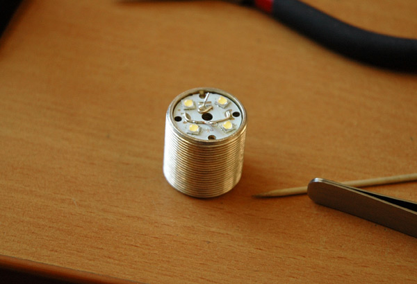
This type connection may be used with 1xLiIon and buck or linear driver. There are all pads (central and side) used
We must deliver about 3.5V volt in this config, and current from driver divided by 4; this type connection ideal for 1x18650 EDC
B: (2P)x2S. Here we have two pair of diodes: each pair parallel and these pairs serial connected. There are only side pads used. We need boost driver with 1xLiFePo4 or buck with 2xLiIon. We must deliver about 7V to our board in this configuration and current from driver divided by 2.
C: Tricky linear. Well, here we need to isolate battery (+) from driver and wire it directly to board; then, after some voltage drop, we deliver it to Linear regulator (because no matter there linear works: it regulate current for the whole scheme). This configuration for 2xLiIon and current divided by 2 too.
Hope it help
Now I understand how 2P2S is done. It was a good graphic, but I was paying too much attention to the wires coming out of the middle hole to see what was happening. If the wires came in from the outside like this, it would have been plain as day.

I was just being dumb. Thank you for bearing with me and providing all those explanations.
Question about the parallel configuration again:
So is that with the positive (red) lead going to both crescents, and the negative (black) lead going to the 3-bar-shaped pad?
EDIT: Answering my own question: It appears that one of the pads for each emitter on a given side is connected to the crescent shaped pad on that side, and the 3-bar-shaped pad is connected to the “other” pad for each emitter, so what I said above appears to be correct.