Knucklehead Buck Driver Discussion Thread

RMM is on the money here. I am no guru on this subject, so I don’t want to be hasty in pointing this out, but the thing is advertised as a 4A controller. When that happens, based on my limited knowledge, 4A is what you can do with it in a best case scenario. In the case of a buck controller “best case” is usually close to the the maximum output voltage and an input voltage that’s just enough higher to get it in regulation. The point is that running a relatively low output voltage (3-8v) and a 1.5x+ input voltage just isn’t going to be the ideal scenario for this chip. It’s not specced for that. This is rarely made entirely obvious in the datasheet, but I think ST was maybe even a little worse than usual about it with this product.

FWIW we still haven’t proven that the LED2001 dies when run w/out heatsinking with an MT-G2. All the ones that have been killed so far have either been by accident or while hooked up to the lower voltage XM-series emitters. I don’t understand the topic well enough to know exactly what would cause them to fail. Mattaus did test v1 on the bench with an MT-G2 and that did not fail.

I arrived at the same place you are at RMM. I think looking at a driver which allows an external FET may be the way to go. I was also thinking of trying to build a simple current controlled buck driver like this one in order to get a better handle on the subject. He is just using a comparator for the actual buck circuit with another comparator to get the PWM in there. I don’t know about the sensing setup he’s got there though. I haven’t pieced together whether it could be adapted to something more suitable for high-power or whether that would call for a whole different setup. In any case it sounds like a simple design like that will not have good efficiency compared to a proper controller.
You guys may well be right but until we try it we won’t know for sure.

My Knucklehead is still attached to the MT-G2. Want me to pull the heat sink off the regulator and run it? See how it does with the larger emitter?

Well, gee, you know I’m gonna…

BRB

I, uh, can’t get it to come off without applying a lot of heat. Can’t do that, for obvious reasons. :frowning:

DBCstm wrote:

Ok, somebody help me out with proof of concept here…when we talk about thermal conductivity I think Silver or Gold. Copper then naturally comes to mind as an economical alternative. When I think of ceramic or silicone, I think insulator. Stop the heat. Silicone rubber oven mitts let me grab a 425º pan out of the oven without getting burned because it DOES NOT conduct that heat to my hand. If I had a copper oven mitt I’d be burned in a millisecond.

So how can it be that in our flashlight world ceramic and silicone compounds are being described as thermally conductive? Seems to me a layer of silicone between 2 pieces of copper is going to shield the heat from going between those 2. What am I missing?

Obviously, those metals conduct heat much more efficiently, but they also conduct electricity quite well. So, even if you could economically completely encapsulate the driver components with them, the driver would have great heat conduction, but wouldn't work anymore due to shorts. The trick is to find (in my case budget and reversible) pliable materials that are as much better than air as possible without creating shorts.

I think you need to freeze it and then pry / sheer it off. No guarantees :wink: Maybe spend some time on Google for tips, it’s been a while since I thought very hard about removing Arctic Alumina.

I’ll just build a new one in a couple of days when I get new boards. No sense in trying so hard to kill this one after trying so hard to get it to live.

Good point.

Hello,

I have to say really great work! It is great to see everyone working together to get the driver working.

Perhaps and since it is open source, Mattaus could upload the eagle files? So we could play around a little bit with the layout.
Also it would be interesting to see the circuit.

And it might be helpful to test the driver not at the maximum specs (4A) but at 3A or 2A to see if it still blows up.
Has anyone simulated the driver in spice?

And just some other thougts to the driver (This are more details than important things…):

First, some people use it with an electronic switch. I would not recommend that, because it will drain the batteries empty quiet quickly.
The Linear voltage supply for the µC always has to be switched on and will consume a lot of current.
Next since I did not see an “Enable Pin” at the LED2001PHR I assume it will consume also current even when PWM level is set to 0.

Next, why do you use the crappy 1.1 Volt (+/- 10%) ref Voltage, when you have a nice accurate 3.3 Volt Vcc with which your ADC can compare the Input.
First you have a bigger scale from 0 - 3.3 instead of 0 - 1.1 next you do not have the +/- 10% which results in a much greater accuracy. Also the tolerance from the resistors would not influence the measurement as much as it would with 1.1 Volt.
New voltage divider resistors could be 100k and 20k. What do you think?

Regards

Can do - but please note that there are already two people actively working on the board. A few different versions of the same design may be alright, but at the end of the day we want ONE available version otherwise it just gets too confusing. Here are original V3.0 files:

https://www.dropbox.com/s/t9qdekq6t5tvdqf/MT-G2%20Driver%20V3.0.brd

https://www.dropbox.com/s/nb3m922c85ga4rr/MT-G2%20Driver%20V3.0.sch

[quote=fritz15] ...it might be helpful to test the driver not at the maximum specs (4A) but at 3A or 2A to see if it still blows up. [/quote]

I've suggested this already, I'm not sure if anyone has done it. I would, but I cooked the only LED2K1 chip I had on me at the time!

[quote=fritz15] Has anyone simulated the driver in spice? [/quote]

I don't have or know how to use spice, but if anyone else does; go for gold!

[quote=fritz15] First, some people use it with an electronic switch. I would not recommend that, because it will drain the batteries empty quiet quickly. The Linear voltage supply for the µC always has to be switched on and will consume a lot of current. Next since I did not see an "Enable Pin" at the LED2001PHR I assume it will consume also current even when PWM level is set to 0. [/quote]

I never thought about that, but you are correct about standby current being high. One alternative is to use a zener diode to filter the MCU power supply but this was this was really only good for two cells, hence why I went for the voltage regulator (larger VIN delta). I guess both have their pluses and minuses.

The LT1761 does have a shutdown pin and draws less than 0.1uA in this mode, but I really have no idea how this could be implemented because the MCU that would control it would also be fed off it lol.

[quote=fritz15] Next, why do you use the crappy 1.1 Volt (*+/- 10%*) ref Voltage, when you have a nice accurate 3.3 Volt Vcc with which your ADC can compare the Input. First you have a bigger scale from 0 - 3.3 instead of 0 - 1.1 next you do not have the +/- 10% which results in a much greater accuracy. Also the tolerance from the resistors would not influence the measurement as much as it would with 1.1 Volt. New voltage divider resistors could be 100k and 20k. What do you think? Regards [/quote]

I...I actually don't know how you would do that? Are you saying instead of using the internal Vref, you can compare against the Supply voltage to the MCU? Would that not be dependent on whether or not the MCU is capable of using its supply voltage as a reference?

Is it just silicon or does it have alot of padding on the back side of the silicon, try it with just a silicon sheet some time

It’s my intention to test at 3A or less but I am waiting for my boards. I could depopulate one of my existing boards and start with fresh components but the process would leave me with a well used board which could skew the results. I have all components on hand in tenfold and await new boards from OSHPark.

When I put the Solarforce tail clicky in the circuit at the negative end of the cell, I intentionall soldered the lead to the driver on top of the spring, much as it would be in a real circuit mounted in a light. I’ve noticed this spring getting very hot, should it? I don’t remember now if the spring had already seen heat damage before I started, but it certainly shows it now…discolored and no longer in a proper coil shape.

Time for a solder braid high current mod

lol, or just take the spring off the switch and solder the lead directly to the pcb.

Some of this has been addressed by others, but I’ll re-address it anyway. In order…

  • I’ll be doing testing at various currents when my boards show up. As I mentioned I have a wide variety of options w/ the sense resistors I have.
  • Not simulated in spice. Like Mattaus I also do not have spice or know how to operate spice. Please simulate it for us if possible.
  • At first I thought you were wrong about the quiescent current, but I see that the LED2001 has a large (1.5-2.5mA) quiescent current. I will look into how to deal with that. All of the rest of the components have shutdown or sleep options with a very low quiescent current. The LT1761 does not always have to be switched on for a momentary switch, but changing that aspect will require moderate firmware revisions. If necessary I will elaborate later. Our big concern remains the LED2001 I think. @Mattaus - are you talking about powering the MCU with a zener like done with 105c boards? I’m pretty confident that would result in a higher drain than the LT1761.
  • I’ve brought up using the 3.3v for vREF earlier in the thread. We will definitely do it, it’s just a flag we set in the firmware. Very easy. So far we’ve been less concerned about battery monitoring and more concerned about incinerating LED2001 chips.

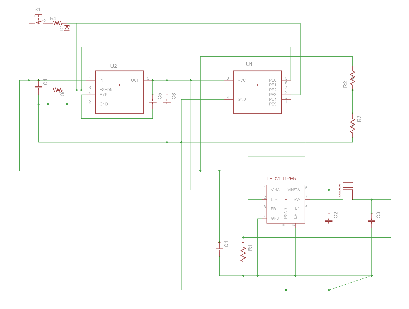
OK, here is the schematic for turning off the LT1761 while the light is off in an e-switch light. Remember, this doesn’t work without moderate/heavy firmware changes.

I’ll describe what you are looking at vs the current v3.0 boards. In current boards the enable pin (SHDN) on our LT1761 would be tied directly to VIN (BAT). Similarly the the LED2001 would normally have VINA hooked to VIN (BAT). In the revised schematic I’ve tied the LED2001’s VINA to the regulated 3.3v from the LT1761, it can’t draw power on VINA while the LT1761 is shutdown. It could still draw power on VINSW though, I’m not sure what I’ve done there is a good thing to do. It could also act up. SHDN is now intentionally pulled low (to turn the LT1761 off) with pulldown resistor R5.

In the upper left we’ve got the momentary button (e-switch) powered by BAT+. When depressed it feeds a limiting resistor and zener diode, similar to the very lossy setup we use to power the MCU on zener-modded 105c boards. The dropped voltage from the zener (let’s say it’s a 3.3v zener) goes over to pull the SHDN pin high, turning the LT1761 on. That same 3.3v signal also goes to our e-switch pin (PB3) on the MCU. Another pin on the MCU (PB0) is wired to pull SHDN high as soon as the MCU’s program starts. When we are done having the light on, PB0 can drop low and shut off the LT1761.

According to the datasheet 3.3v should be enough to power the analog circuits of the LED2001, but I really don’t know that that part of my changes will work. I don’t know that the LED2001 will be stable and I don’t know that this change will get the LED2001’s quiescent current under control. Obviously VINSW can’t be powered by the LT1761, so if we wanted to switch VINSW we’d have to add a big FET and that’s dumb.

I’m thinking of making a heat sink out of copper, in an optimized manner. If I cut a notch into a vertical riser of copper that is sized to fit the pad of the regulator, leaving a wall between the regulator and inductor, the copper sink would be sitting on the pad of the board, the regulator would be sitting on the sink, with more sink above the regulator and finned on top for dispersal. This would raise the regulator, so the pins would have to be extended through short solid copper wires to the pcb. Thus, the regulator’s heat would disperse into the pcb as orginally designed and into the copper sink as well, with the wall towards the center of the board taking heat up into the finned upper area. Does this make sense? It would be like a copper tower sink, slotted to accept the regulator, with the pins coming out the sides and reaching down to the board.

Maybe an 1/8” of copper between the regulator and board, a 1/4” of copper above the regulator with finned top surface. That should allow the regulator to run at max.

I can take the MT-G2 out of my circuit and put an XM-L2 back in, to test the regulator at full output with the heat sink on top. I see the logic in what’s been said though, and have my doubts as to whether or not this regulator will handle the spread between the XM-L2 and 2 cells. Sink or no sink. Since Matt was thinking MT-G2 all the way, I think it may very well work best in that scenario. Toned down to 3A, pushing an MT-G2, I feel like it’d be right in it’s element.

Will be testing that as soon as possible.

Thank you for your reply.

Yep, I just saw everyone blow up their drivers…

Unfortunalely I did not find a spice file for the LED2001 althoug I tried out the edesign suite but it did not really help.
It just showed that you have about 2.4 Watt losses with a MT-G2 (4A, 6.75V) and about 1.26 Watt with a XM-L2 (3A, 3.35V) with about 8.0 Volt supply voltage.

I do not think your changes will work. I did not see the original circuit, unfortunately the file is offline.
You want to control the PWM with an electric Switch between Vcc and PINx. Also it is possible to shut the power source for the ATtiny off but then you can not switch it on again.
Therefor I see two possible solutions:

  1. A small capacitor dischargers, when you press the electronic switch and powers up the µC.
  2. A capacitor is charged while light is on and powers the ATtiny while it is in sleep mode. The µC has to wake up, I don’t know, about every 10 Minutes and charge the capacitor.

That would solve the problem with the LT1761 but there are still about 1.5mA from the LED2001. To get rid of that drain current another fet would be required, which is compared to the rest a large component. But if we use an external fet we also could use another led driver IC without an internal fet and a Shut down Pin…
All in all I think that this configuration is not suited for a electronic switch.

Sorry, I read through the thread but must have over read it.
@Mattaus: As mentioned it is easy possible with an ATtiny13A as well as the 25/45/85 models.

Regards
Fritz

Basically the changes I made allow the ATTiny to latch the LT1761 in the on or off state. After latching the LT1761 in the off state the ATtiny is unable to latch it back on by itself (because the ATtiny has no power and is not running). When you press the momentary switch the LT1761 is temporarily powered up. This should be long enough for the ATtiny to latch the LT1761 on before the momentary switch is disengaged.

Also note that the LED2001 has two VIN pins, the VINA pin and VINSW. I think that VINA can tolerate 3.3v, so I’ve got it running off of the LT1761 as well. I do not know whether the 1.5mA+ drain is on the VINA or VINSW pin though!

Here is the original circuit (before my changes):

RMM should be getting boards and components in any time now and I was wondering if the op could be kept somewhat updated with info on this. Some, like me, will need the at tiny preflashed with a ui that has the lower pwm frequency and if we all use the same levels we can compare apples to apples. Even if a new board design is imminent I would get both in order to compare them side by side but for now I’d just like to get one built as a two-board unit to ease the strain on Dales pocketbook and see what affect if any a direct thermal bond to the bottom of the buck IC has on performance.

Maybe posting some sort of testing protocol with standards for sense resistors and the results for each. This will give us a starting point so we can plot various drive currents vs input voltage in a larger sample size.

Dale’s pocketbook is no longer under stress. Regretfully, it passed away this morning and the burial services will be held as soon as I can scrounge up funds for enough dirt to cover it. :frowning: