Dead body outline with “heat sink or else” inside.
Heh, this one might be the closest so far. I’m cautiously hopeful that noise issues may be the real killer, especially combined with high dissipation. Hopefully Microa has some insight on that. If that’s the case layout changes could potentially reduce the need for special heatsinking.
EDIT: Order #YF1ViyO7 received from fab. <— I guess I’ll get some of the original Knucklehead 3.0 PCBs to test with soon.

I think that can go lol. Along with any other unnecessary text or logos until we get this working reliably. Wight is driving this at the moment and I am happy to help out where possible. I have a minor revision of the original board done, but I'm not sure if it's worth releasing given these other changes being made. What I'd ideally like is one driver - e-switch or power cycle. Wight has explained to me that this is still possible so I won't step on any toes and confuse us more!
Very beautiful, Mattaus’ logo looks more artistic than on solid background.
Different color silk screens are not possible with OSH Park, but there is no reason why we can't do something like that. I'd lose my logo and replace it with BLF.
Still, we'll worry about it later lol.
If anybody wants to pitch in (WarHawk-AVG seems to like this stuff? ![]() ) I’m looking for a couple of components:
) I’m looking for a couple of components:
- a zener diode in the 0603 package. This diode should be >2.31v and <3.8v, try for the middle please.
- a regular diode in the 0603 package. This diode should be appropriate to stop whatever the zener above is producing.
I’m having trouble fitting in regular sized diodes and if we can come up with decent options in the 0603 or similar sizes that would be great. We have all the space we could want for this stuff, it’s just that using it eats up precious copper pour or cuts off sections of copper pour from one another.
EDIT: or whatever tiny package, use your own judgement.
Hah…that’s great! I really like Mattaus new signature silk on the board…very cool
Heatsink or Die…awesome ![]()
I like that shot to pieces look. It’s somehow appropriate.
“Heatsink or Die” is written in a font called “Nightmare”.
>)
Yes, but if one holds the Shutdown Pin high, it also holds the Input Pin high…
Perhapts adding another diode will prevent this. The second version could work.
But it is useless to debate over this, while the driver is not working properly.
I just looked at the datasheet and I think you are right. I think I misunderstood it. It would be great if it completely disables the LED2001.
Regards.
I agree. Several of us will soon be testing the v3.0 configuration, it has taken a long time to get boards or other supplies.
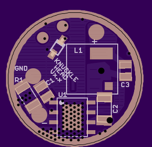
In the meantime I have laid out the stuff from the schematic and done the revision Microa suggested. Mattaus pointed out to me that I had the inductor too close to the side in my latest work, so I took the opportunity to use a hack to move it over: I did not use the whole inductor pad, so it will bridge the appropriate traces on the PCB. Since I’ve got such a strong offset on the inductor I added an unconnected pad that I hope will help make sure it doesn’t skew when reflowed. I need to fix the tstop layer on that and I need to fix some minor DRC issues. Also, the lower pad of the inductor does not touch the upper pad of C2, but I will might manually increase the amount of tstop applied between them just to be sure.
Microa, what do you think of the noise situation now?
Pin 4 on U1 is on the ground ring, or is that what it’s supposed to be?
Per the schematic…yup…and considering all those vias running thru the foot pad kind of a no brainer ![]()
I checked it should be alright.
If possible, try to avoid the via overlay the solder pad which may cause bad contact and not easy to find out.
I reflow the inductor side, but the battery side I solder by hand with my Hakko 888 station. With everything being so close together, gonna be a bear to use an iron on the battery side. Oh well, if it makes it work it’ll be worth it.
Wondering now what I’m gonna do with the 12 boards that haven’t even made it here yet…
How many sets of parts do you have?
I have 10 complete sets of components, with 3 more sets sans inductor.
In this case, yes that’s what we want. Don’t take anything as a given here, I’ve made (and corrected) many mistakes so far.
Great, thanks. I agree that the via / solder pad overlay is a problem. Mostly I have offset the via to the side where I was forced to overlay. Some of the bad spots are left over from earlier revisions. I can clean up the LT1761 for example. C2 I think is OK because it is big. The LED2001 pin 4 that WarHawk-AVG asked about can have either have vias removed or maybe change the pattern to help the reflow.
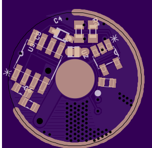
I agree. The e-switch version will be a total bear to assemble by hand. It may not be possible for me, I may have to reflow both sides. Bear in mind (hur hur) that many components on that side are not necessary for a clicky build. There are 3 components and one “solder jumper selector” between the ATtiny and the LT1761. You’ll have to use the solder jumper to select no matter which build you use, but for the clicky switch you can leave out all 3 components there. At that point I think the build looks a lot easier. Hopefully if this thing actually works we can do some tweaking to clean it up and possibly make it a tiny bit more friendly for soldering. Only so much can be done of course unless we could reduce component count, but like I said it’s really mostly an issue for e-switch builds.
In terms of what to do with the 12 boards you’ve got… the MCU side is just fine. If you have a need for e-switch 7135 based MTG-2 drivers you can use the MCU side of the board hooked up to a 7135 slave board instead of zener-modding a 105c. As mentioned here a regular zener mod 105c does not get along well with an e-switch setup, it will quickly drain batteries while off. I don’t know exactly how much better the v3.0 board with LT1761 would be with a sleeping ATtiny like the STAR momentary firmware does, but I’m sure it would be better. It might be great.
On another note, I’ve got another potential band-aid for these bad boys getting zapped. It’s work I don’t want to / can’t do though. The LED2001 has a soft-start (see section 5.3 of the datasheet) which we disable as far as I can tell. It’s hard to tell because the datasheet is kind of crappy in describing this feature. It says in section 5.3 that the soft-start is disabled when DIM is pulled high. But if you are not using DIM you are supposed to connect it to VINA, which as far as I know pulls it high all the time. So there seems to be no scenario where the soft start would be enabled.
The important thing here is that the ST engineers thought it would be a good idea to use a 1ms soft-start to minimize stress on power components (and decrease inrush current). Implementing a 1ms soft-start in firmware might be possible. It should be visually undetectable but could help with LED2001 survivability.
I just thought that this was something I should mention. I don’t plan to try and hack together soft start code and I don’t expect anyone else to run out and do it either… I’m not even confident that it is needed in any way.
My only concern with the latest revision is the size of the inductor pads. The inductor is required to handle quite high current (up to 8A) and I feel that the lower pad is far too small for that amount of power.
I can see an easy solution to this, but seen as I am at work for the next 8hrs there is not much I can change. The thick trace running from the top of the LED2K1 could be moved to the left a bit (that area seems to be all ground). The bottom inductor pad should be able to be sized up to match the other pad.
That's the only thing that really sticks out to me at the moment.