Planning and competitor circuits boards
First of all, what is already on the market, and how to come up with something that is either better, better and cheaper, or more useful?
We all seem to know the typical Nanjg 105c type drivers. Lots of options between modes and output current.
We have several cheaper direct drive curcuits.
We have various 3A,4A and 5A drivers sold from intl-outdoor/fasttech with more features (and taller size).
We have LD-25.
Basically, there are lots of 1-cell, 17mm driver options out there. As far as I know, none of which have a “boost circtuit”. Why boost?
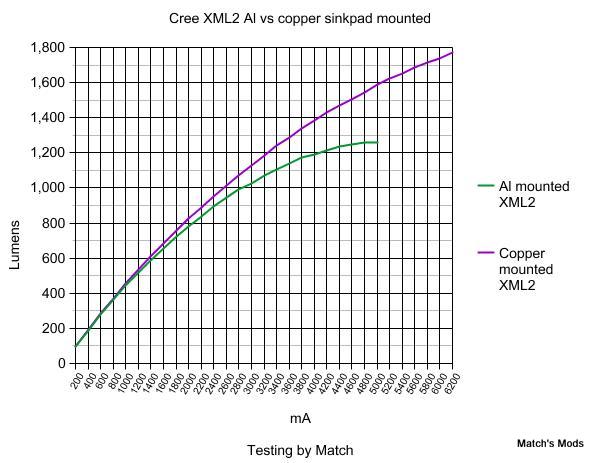
If we plan go go beyond 4A in combination with XM-L2 forward current is an issue when using a single cell. Especially if using a cooper star.
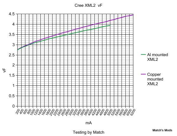
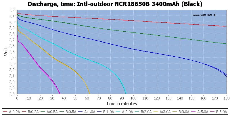
Even pushing 3-3,8A+ with XM-L2 is hard for a good protected cell. Just look at voltage drop after 20 min on the chart below and compare with forward voltage in the graph match made.
If the lightmalls driver should offer something more I think it should be a boost feature.
I would like to see following specs:
*Operating voltage: 2.7-4.5V
*Regulated 4,2A boost circuit
*Modes: 100% - 20% - 2% (remember guys, these values are from 5A, not 2-3 like most other circuit boards)
*Mode memory
Hopefully at price around 5$ and mounted on a single board. Everything on one side if possible. (I have no idea if that is realistic)
Optional features that could add 1$
*Reverse circuit protection
*Thick silicone wires
*Spring for positive connection to battery
When using one cell that would be a great driver for:
1 XM-L2
3-5 Nichia in parallel
2-4 XP-G2 in parallel
_
Naturally, I like Relic38 suggestion. Using boost.
I also like Slim Pickens suggestion and his thoughts about XM-L2.
I think XM-L2 and 3,5A+ should be the main goal, and also having features that makes it better suited than what is already out there.
We need more power for those XM-L2's! Definitely "boost" for a 1 battery C8. Now if they could use a PIC/MCU chip we can custom program, all the better!
He is reading the Posts, so if you have a comment to Bill, leave it here:
Dear Flomotion
I read the posts already,thank you very much!
like we talked ago,if we make the circuit board at 5A in 17MM,it is very difficult for using,also if want the current at 5A,it need very good condition
such as the good battery,good switch and copper mount with the led,so when the driver done,i think it can not up to 5A,don’t you think it is?
i think it can up to about 4A in 17MM board.
so i think i will make the following drivers
1):
Voltage: Max4.2V - Single Li-ion
Working current: Constant current Max in 5A,(depends on the other condition)
Dia: 17MM
Memory: Yes,with Memory mode
Modes: High(100) - Mid(30) - Low(5) please let me know we make the moonligh?(05?,i went to factory and try 0.5%,we will not see anything if too low)
2):
Voltage:3.7~15V three Li-ion
Dia:20mmboard with 21mm Tailgate
Working current: Max 9A
With Memory mode
Modes: High(100) - Mid(30) - Low(5) please let me know we make the moonligh?(05?,i went to factory and try 0.5%,we will not see anything if too low)
A ~17mm diameter, regulated 3.5A to 4A boost driver for 1x18650 will undoubtedly rock the P60 world. If these drivers can do that, they would be the only driver I would ever buy for making XM-L2 P60 dropins. If they are affordable and offer good regulation for the majority of runtime with XM-L2, I would buy several as soon they were available.
* If Mr. Zeng is also having his engineers work on a buck driver, I put together some recommendations for specifications:
Output between 5A and 5.5A (rather than 9A) is in-line with what BLF modding crowd wants in this new era of widespead SinkPADs. IMO, 5A would be a great drive current for XM-L2 on a SinkPAD PCB.
Regulated voltage range should be 6.4V-16.8V (two to four cells).
The driver should have low-voltage warnings for 2, 3 and 4 cells. Once V-battery drops to <6.4V, <9.6V, and <12.8V (3.2V/Cell), the driver kicks down to Medium or Low (I like FlashPilot’s suggestion on this).
Nice to have, but superfluous: Shutting the light off and turning it back on between t=1 and t<5 seconds later nullifies the low voltage warning for the current duty cycle.
We should be able to alter the output current with an easy sense resistor swap, so the sense resistors should be easy to access with a soldering iron.
Of course, input from other members is welcome. Speak now or forever hold your peace
Let’s not get ahead of ourselves and throw pricing in the mix yet. There’s a tendency for the actual price to turn up close to whatever a customer hints at being comfortable with.
I would prefer Bill to come back with whatever pricing makes sense to his company and we (via Flomotion) can negotiate from there based on volume and tweaking the design.
Edit: Better, thanks Slim Pickens
Am I the only one thinking something like Dr Jones luxdrv UI would be awesome? Code’s freely available (although they might need to recode if using something other than the ATtiny13A). It would take the UI into more widespread availability without having to DIY.
Flomotion and Mr. Zing. This is great news and I believe the need for such drivers has been very long overdue. In keeping with what others have asked for in several other mod threads, I think there is a good market for 3 different regulated drivers:
1) 17mm regulated 4.2V 4A boost driver.
2) 20mm regulated 6-13V 5A driver
3) 20mm regulated 6-13V 10A driver
Details for each will hopefully include the following:
Great regulation and reliability is a must
Low voltage detection automatically changes to medium mode
Thermal overload protection at 90C automatically changes to medium mode
4 mode with memory - 100/75/30/3%
I feel by far that most people do not want: strobe, SOS, blinking low voltage detection/thermal overload detection. Just automatically switching to medium mode and keep it there; will suffice without becoming an annoyance.
Driver 1. needs to be a boost driver as many have suggested. Regulated for sure. 4A or a bit more
Personally, I don’t want “moonlight” mode or more than 3 modes. Unless there is a hidden group.
Driver 2. I would prefer boost/buck. regulated @ 10A. But with the ability to remove resistors for less output. It should have 5 resistors that are easily accessible. About 1A less for each resistor removed would be genius. (if that is possible)
I am no fan of drivers that makes PWM whine . Please make it as silent as possible.
i would like to knthe amps in 4A,should it boost or buck?
the driver i want to make it as below
Dia:17mm
PWM:More than4K
Voltage: 4.2V
Modes: High100-Mid30-Low5%
Memory mode
With Temperature thermal protection and low voltage protection
now,for the driver,should be boost or buck?
the driver i would make it as below
Dia:17mm
Current:regular 4A boost
PWM:More than4K
Voltage: 4.2V
Modes: High100-Mid30-Low5%
Memory mode
With Temperature thermal protection and low voltage protection
 .
.