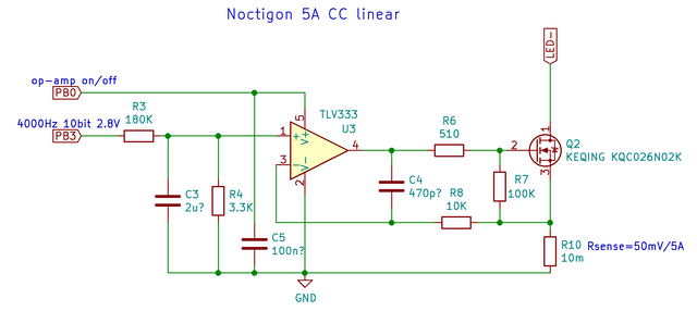
Only this one that I believe @thefreeman drew up
It must not be possible to seperate the turbo fet from the regulated circuit. So not true direct drive. That makes sense right? Thats my guess.
Only this one that I believe @thefreeman drew up
It must not be possible to seperate the turbo fet from the regulated circuit. So not true direct drive. That makes sense right? Thats my guess.
Ya. I mean no turbo fet. Just use the regulation fet for turbo. But I can see that it wouldn’t be as bright.
“Turbo fet” reminds me of I like big butts by sir-mix-a-lot
Led4power linear drivers do that, they turn the mosfet fully ON for turbo.
As people mentioned it means that the currents passes through the sense resistor, which in case of Noctigon linear drivers is 10mR, decreasing a bit the max current (not a huge amount).
A lot of power is dissipated in the sense resistor, exceding its power rating, but that seem to be ok on L4P and FF driver (buck+FET), probably thanks to the thermal regulation.
But I’m not sure L4P do PWM diming between regulated and fully ON, the feedback circuit (op-amp) must be fast enough to do that above 16~20kHz to avoid audible noise), not having smooth thermal step down is kind of bad IMO.
About regulating for the full range, up to 15 or 20A etc… that’s possible, but the dimming resolution doesn’t change, thus the min output is higher.
Also a lot of power is dissipated in the linear FET at high current if there is a large voltage difference between batt and Vf, it increases at first when current increases, then at some point the voltage difference becomes small enough that it starts to decreases. The power dissipation makes sort of a bell curve.
So at turbo you get a bit of power dissipation in the fet, then when it starts to step down, it shoots up because the voltage difference between batt and Vf increases, if it’s too much it can blow up, that actually happened to @Haukkeli in a DT8K, very low DCIR cell and very low Vf due to 8 LEDs, I think he bypassed the spring which made it worse (more voltage to drop).
Even if doesn’t blow up it affects the thermal regulation negatively because the fet is close to the termal sensor, so the output will dip too much after turbo.
For that reason it’s better to not ask the 9 or 12A driver in a special order, and let the the high ouptut part of the ramp dissipate heat mostly in the LEDs instead of the linear FET/driver.
Thanks that all makes sense. Ya I love these newer crop of low vf LEDs, but it definitely causes a lot of heat with linear regulation. They’re getting low enough buck drivers will start to make sense with a single cell. Previously you’d barely get any regulation with them with high vf like the xm-l2. Problem is the big coil necessary for large currents
Oooohh so that’s why. If I smooth ramp down from turbo theres always a big spike in temperature going from turbo to top of ramp, even though the flashlight is dimming. I’ve been meaning to ask why that was forever. Thanks, makes total sense.
So I got a question still. Besides the obvious, why the double FET? Any specific reason?
I ask because Hank uses 2 of the same FETs for his 9A linear that simon uses one of in his 12A DD FET
Surely there’s a better fet out there specialized for these two different applications? Cost maybe?
Also, I found some photos of an older 5A linear hank drivers with only a single FET so it must be possible.
Basically trying to figure out is the double FET is necessary or just beneficial, and how the two work together
The reason why driver heat increases when you step down is because lower modes is using the linear driver. Which is burning off excess voltage as heat. Wherein using the turbo get at 100% is extremely efficient, driver wise.
Convoy only uses one driver because they aren’t using a fet for turbo. It’s not even a turbo really just high. Every mode is regulated
…Was that for me? If so theres a couple misunderstandings here lol
I didn’t ask the questions you answered. Appreciate the sentiment though lol. We’re talking about different drivers
It was late when I wrote that though so could be my fault for the confusion lol
That happens a lot when folks do ‘drive-by / stealth’ replies instead of clicking ‘reply’. I don’t think using ‘reply’ costs more;-)
You have to make the distinction between a MOSFET used as ON/OFF switch, used in a direct drive driver, sometimes called ”FET driver” (unregulated, and PWM dimming) and a MOSFET used as a variable resistor ( in its ”linear region”) in a constant current circuit (an Op-Amp, sense resistor and other passives) in a linear driver (regulated and analog dimming).
And to make the distinction clearer it can be refered as linear FET, but any mosfet can be used as switch or linear (although some have better characteristics for one or the other use)
An AMC7135 is also a linear driver, with a similar circuit but all inside an IC, so there’s a MOSFET in there as well, but it’s only PWM dimmed, because it doesn’t allows analog dimming.
There’s a Linear channel for regulated up to 9A and a direct drive channel for turbo.
You get both regulated modes on the lower end and max output on the higher end, it also allows for lower min output, the 5A linear+DD FET are better for that, we could also imagine a driver with another linear channel with a max of 10mA to get even lower output, that’s kind of what a 1+7+FET driver does, there’s 2 7135 linear channels, a small (350mA and big one (2.8A), and then a DD FET for turbo.
There’s just one linear channel, on the current drivers there’s both and if he only wants a retulated output, he just disable the Direct Drive FET in firmware instead of making 2 different drivers.
Dunno how this one works, I mean it’s possible to make a (somewhat) regulated direct drive driver, but I’m not sure that’s it. There’s a big diode, and then 2 transistors (BJT ?) maybe used as some sort of feedback circuit, I don’t know.
Yes, I should make the distinction for this discussion, it gets confusing quick lol sorry.
So about the specific MOSFET choice. I assumed and you confirmed that some FETs are better suited to linear and some better for switching.
So why is the same FET being used on both channels? That’s what I’m wondering about.
OHHHHH… I see what I did. Whoops. That’s my bad. I see what I’m doing now…
When I said he uses the same FET for linear and turbo I meant to say both the big trench N-channel power MOSFETs on his linear+FET driver, the linear channel FET and the direct drive Turbo channel FET, are the same part number. Not that it’s the same 1 component. Oops…that’s on me lol. Sorry
I believe I linked to it up there, but if not it’s the WSD2090DN56.
So, on Hank’s linear+FET drivers there are two of those 2090’s. One, I assume, is the linear channel and one is the DD channel. I assume.
And on the tint ramping D4Sv2 he uses 3 MOSFETs. It wasn’t always the case, but recently it appears, they are all 3 of them 2090’s.
There’s also the dual channel d4k drivers that have 3 of the same FETs on the driver. I think theyre all AP2045Q’s. I assume one of those is used as a direct drive.
And simon on his 12A unregulated full direct drive with only PWM dimming driver also uses 1 of those 2090’s.
So if there are FETs better suited for linear and ones better suited for switching, why the same part numbers on everything? I assumed you wouldn’t want to do that. Are they just a good all-rounder? Or cost? Compromise? Idk.
Oh it’s not regulated at all. Direct drive FET on all modes, PWM dimming. That giant diode is funny eh