Liners drivers using Fet at 100%

We have these linear drivers. I’ve seen them in 5a, 6a, 8a, 9a, 12a. Emisar/noctigon uses them with fets added for turbo. But why add a fet when it has one already? Or why limit these other drivers to a set current. And the higher current ones are generally on bigger boards. But there’s 15mm fet drivers.

If the fet is being used in a linear way, I.e different levels of closed, why can’t the same fet be closed 100% for a turbo?

Are you talking about how the linear drivers all have two fets? Because if so id like to know the answer to this too. Are the fets always being used together, or is one a direct drive? Theres two channels in anduril on those linear fet drivers and that makes sense for the smooth ramp but why on the convoy drivers? Idk. Id like to know. So cant help you there…

Shape of the ramp mostly i think. In my 9a vs 12a linear thread this is discussed

I think your words are combining three separate factors. (or Im confused and or dont undertstand your questions)

Linear 7135 chip,
Direct Drive FET chip, and
Percent of Pulse Width Modulation

Lets see if I can help unpack those factors with you, using the driver in a Wurkkos TS10 as an example.

The Wurkkos TS10 driver has both a Linear 7135 chip, and a Direct Drive FET, and it uses PWM to control the output from either chip.

In the TS10, the 7135 provides the linearly regulated lower modes, up to about 100 lumens

linear outputs of 100 lumens or less, will maintain a steady (straight linear) brightness, even while the battery voltage drops.

PWM is used to change the brightness during 7135 linear operation.
Plus a Thermal Sensor is used to limit the 7135 if components exceed a set temperature.

In the TS10, at outputs above about 100 lumens, the Linear 7135 is Off and the Direct Drive FET is On. The FET output is not linear, the LED gets dimmer as the battery voltage drops lower.

PWM is used to change the brightness during FET operation.
Plus a Thermal Sensor is used to limit the FET if components exceed a set temperature.

hopefully I got some of that right… here are a couple of links that can explain it better than I can:

Understanding the difference between Linear, Buck, Boost and Direct Drive drivers
and
FET+7+1 driver

Does any of that help to clarify what youre trying to figure out? :wink:

I thought the 7135 stayed on until 150/150, no? Because in anduril PWM1 stays at 255 all the way through PWM2 ramping up and only goes to 0 at 150/150. I thought it stayed on until then. Or am i wrong about how that works?

And ya agreed that OP is talking about a few different things there.

1 Thank

I honestly dont know… I just like to display my incomplete understanding, in hopes that someone will help me learn better. LOL

Hopefully someone else can explain in more correct detail…

Convoy linear drivers uses two MOSFETs, and i believe that it’s because RDSon gets higher at lower battery voltages, and by using two MOSFETs RDSon can stay low for longer, which allows it to stay longer on regulation at higher currents.

Yes, the 7135 stay on (100% duty cycle) until 150/150. It shuts off at turbo.

1 Thank

One (on some drivers smaller) FET is part of the linear regulator circuit. The other direct drives the LEDs from the battery for higher output near the top of the ramp.

Because with a linear, brightness is controlled by regulating output voltage. They are constant current drivers, and the amount of current is selected to not destroy the LED from overcurrent at the relevant voltage.

The regulated ramp hits max at a level that varies depending on firmware but is generally between 90 and 130, then increasing amounts of FET are added and the linear is off at level 150 where the FET is 100% on (as then the linear would theoretically slightly reduce output).

1 Thank

Thanks for the explanation. I know how fet + 1 drivers work. I’m talking about the linear drivers emisar and convoy use.
They use a mosfet, and control brightness not with PWM, but in a linear fashion by controlling how much the fet closes by controlling the gate voltage. As more voltage is applied, the mosfets resistance decreases and current increases(brightness).
But you’ll see that these type of drivers typically have a max current available. So they’re never fully closed until Vbatt=vf (minus other resistances).
My question is why? With hanks drivers, he uses an additional fet for usually 130/150 to full turbo 150/150 which is 100% closed. But why not use the linear fet all the way to turbo.
I understand not using a fet driver to protect the emitter. But in this situation, full cell power to the emitters is in the design. So why two fets?

Thanks for confirming. Ok, so I’m clear on that part. The part i dont understand is what components are the linear channel and what are the direct drive channel. Like, whats PWM1 if theres no 7135.

Theres a bunch of variations, but theres usually 2 or more big FETs, like two wsd2090dn56’s, an LDO linear voltage regulator type thing, sometimes another different fet, sometimes not. The dual channels have 3 smaller fets. You get the idea.

What fet is doing what, or are they all working together is what im confused about. When its fet+1 i get it, the 7135 is the regulator, but whats the regulator when theres a bunch of fets on the driver. Is one a dedicated direct drive?..Maybe i should start my own thread for this lol

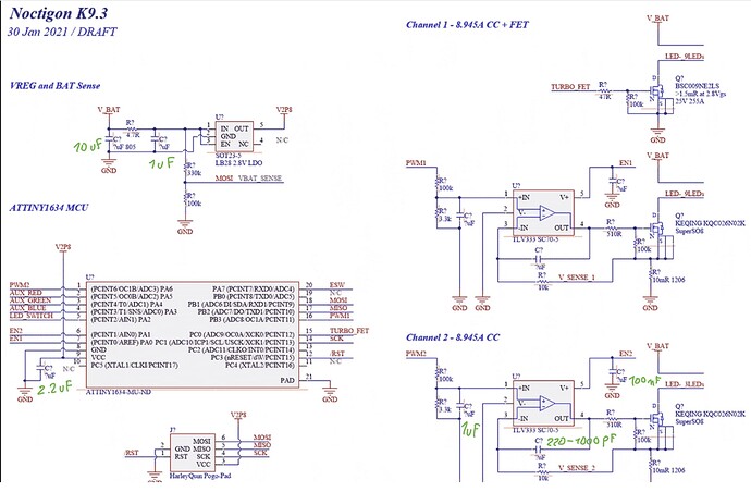
It’s an opamp-based linear regulator, a PWM signal is used as the input, which is tuned using a voltage sense resistor to produce the correct output. I don’t fully understand everything about the principle myself yet (primarily around some of the resistor values), but here’s a schematic:

The two FETs would be one for the linear and the other for direct drive (generally connected to the exact same output current path). The LDO would be for the MCU’s power supply.

Usually the linear. There is a FET as part of many linear regulators, controlled by the opamp. Some lights do have a FET only, controlled directly by PWM only, but that’s relatively rare.

1 Thank

My guess would be because the linear regulated circuit uses a sense resistor which adds a bit of extra resistance in the overall circuit.

To get full turbo requires a second circuit without this sense resistor.

1 Thank

Ok that makes sense thanks. I forgot about the sense resistor. DD current may be too much for it too(sense resistor) and it would burn out

1 Thank

Thanks that schematic is helpful. I can use that.

Any chance you have any more of those lying around? Lol

1 Thank

The entire linear itself also has resistance, and in addition, because it’s constant current, it’s just not providing the full output the battery is capable of.

When you’re going for max output, direct drive will always have more output than through the linear.

That’s the only one I have, but let me know if you find any others because I’m still not 100% on driver design.

Yes but the thing that is giving the linear regulation is a Fet. It just isn’t closed all the way. So if it’s closed all the way, it is direct drive and has no resistance (very very miniscule. Because it’s a fet)

The FET itself has near-zero resistance, but the linear circuit itself doesn’t, and is still a constant current (i.e. less than the battery’s max output) due to the opamp rather than direct drive, while the DD FET is separate and bypasses the linear entirely for more output.

Would the microprocessor not tell the fet to be at 100% closed at turbo, and it would be close? I understand the extra resistance in the set up, would limit some output, but I don’t see why the system can’t get out of regulated mode for turbo With only the one mosfet

Because there is a FET as part of the linear regulator. There are a load of other components in that current path. The second FET just connects the battery directly to the LEDs.

1 Thank