So I'm reviewing a 3x XM-L2 bike light from GearBest. The LEDs are in parallel and it runs on a standard 2S2P battery pack. I was measuring current at the emitters and decided to try to measure the voltage across the two emitter leads too. The voltage readings seem low, especially on low mode. What is going on here? Driver circuitry affecting my measurements?
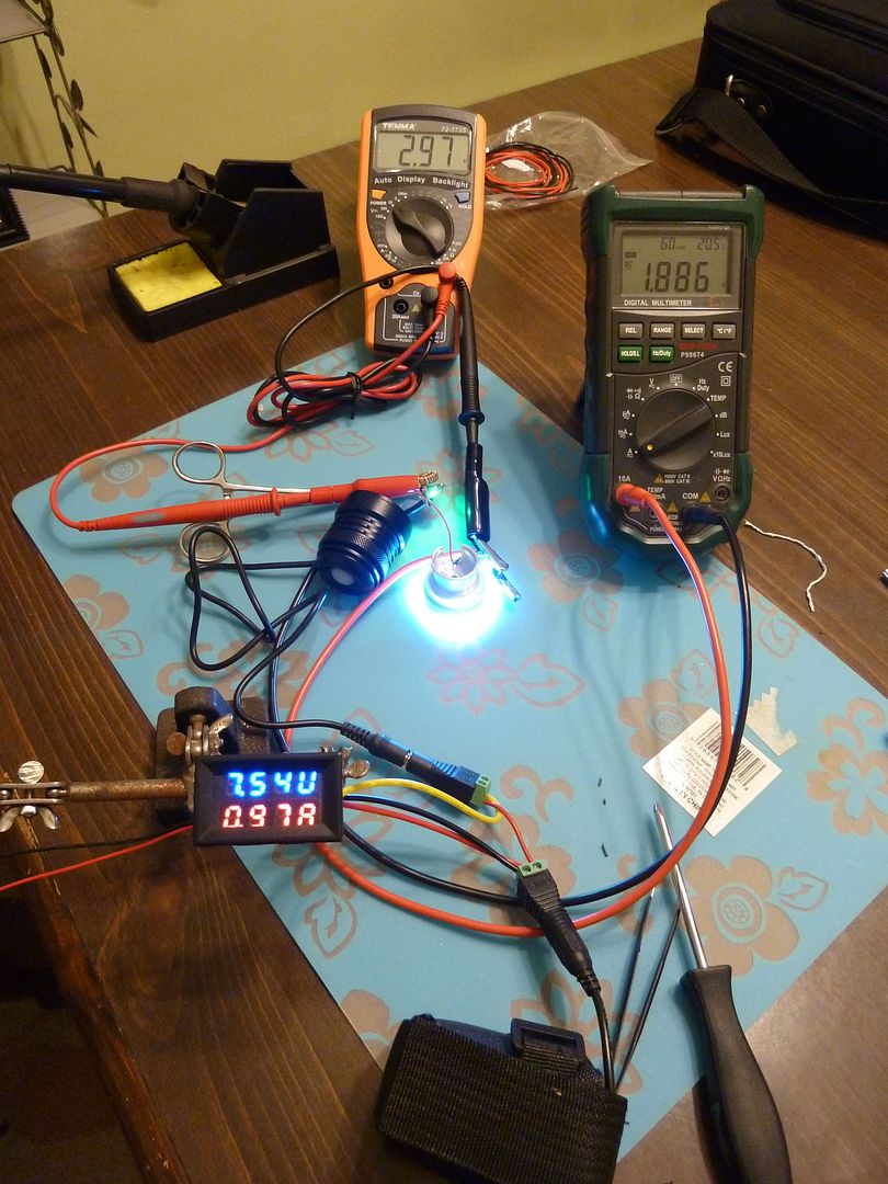
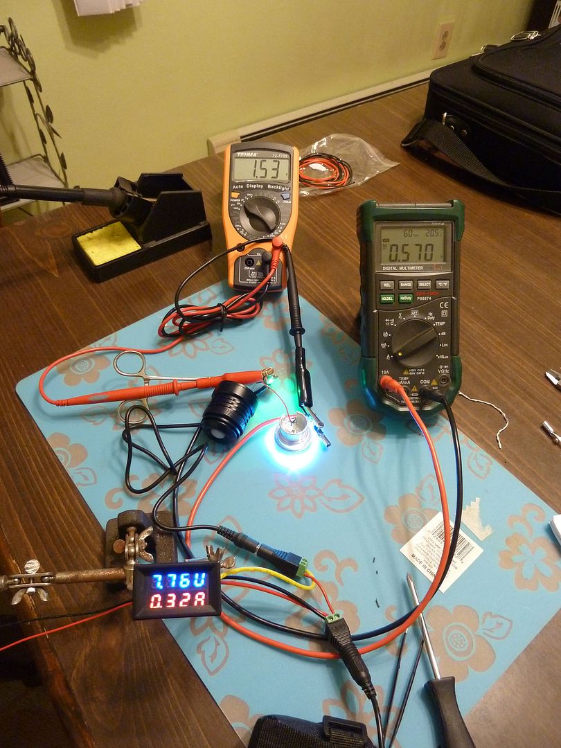
In these pics, the plastic Voltmeter/Ammeter display is showing the voltage and current coming off the battery pack to the driver. My green DMM is showing emitter current, while my orange DMM is measuring voltage across the emitter leads. Battery pack voltage without load is 7.88v (won't charge above 7.95v, but that's another story).
If I look at the datasheet of an XM-L2 LED (xm-l2 led datasheet - Google Search) then the Vf is about 2.85-3.3 V depending on the current. So it looks OK to me.
It's definitely not on low. It should be no lower than 2.5v (and likely higher than that). And the 2.97v at 1.89A should be closer to 3.1v, but this one doesn't bother me so much.
Or is something going on because the LED's are in parallel? Shouldn't be, right? I'm not the only one seeing this low voltage on this same light.
Sorry, didn’t see the voltage on the low setting. looks OK on high then:P
Don’t know exactly what voltage is shown on a DMM if the LED is PWMed.
If the duty cycle of the pwm is 50, will the Vf be 50?
I can’t remember where I saw it, but I think I recall some post on BLF where someone said the Vf of parallel emitters is normally lower than one emitter. Perhaps it is similar to the effect of putting resistors in parallel making a lower total resistance? Or maybe I’m just remembering that wrong, or I’m just stupid, or both! J)
I don't have time to look up the Vf chart, but wouldn't the current be split between the 2 emitters? So each would be receiving about half the current.
What I was saying is that I assumed the 2S2P battery pack would be more than sufficient for the three parallel emitters, so I thought that couldn’t be the reason for the low Vf. I stand a great chance of being wrong, however.
Yes. Sorry, I confused things about amperage. Yes, LED's are splitting that 1.89A, so 0.63A each. Of course the 0.57A splits to 0.19A. Still doesn't explain a 1.57v vF, does it?
I don't think it is the reason for low vF (esp. since it handles high for 80 to 90 minutes just fine), but this battery pack is junk. Of the 4 cells, I believe 2 of them are "dummy" cells (measure 0.00v across each and are wired incorrectly for a proper 2S2P arrangement) leaving two cheap weak cells to handle the load. I've not tested the two working cells yet, but will. Actually maybe I'll try them on my SolarStorm X3 which pulls around 2.6A at 8.4v. I bet it won't handle that load well.
There is definitely PWM because it shows in my camera. It doesn't look too bad in the camera (not as bad as others), and I don't notice it with my eyes.
I went with the 30V, 10A red & blue display. I bought from US Seller NY Platform which I've dealt with before. See post #12 in this thread for more pics and my link. No idea what they can really handle. They do come with really thick leads which is nice to see!
I think the PWM guys above are correct. I just read in something unrelated that a typical DMM samples voltage readings at a pretty low rate (didn't specify rate) and average the readings. Not sure if that is true, but it sounds reasonable.
I would think it it would have to do with the PWM. Don’t forget your meter is set to DC. PWM is not really DC, it’s current being turned on and off very rapidly. Just because it always flows in only 1 direction doesn’t mean it’s the same as constant DC. The LED can tell the difference, doesn’t shine as bright, perhaps your meter “notices” that too and “thinks” that it is measuring a constant DC current, but at a lower voltage.
I would think that a more sophisticated meter could read the peak voltage of the pulses