No thanks. The purpose of the test (for me) is to see how usable the light is.
We all know how bad 7135’s can be from batch to batch and how to cook LEDs.
I can’t measure efficiency in any scientific way (what you really want) so this is what you get. I will reflash the stock board though and retest even though the driver has no pads and 99% of people can’t do it.
Most of my collection is FET+N+1 and it has its place but in lights with poor thermals you need everything you can to make them usable and that fits this light.
You have nice light sphere. I ques i know method how to measure efficiency.
Connect Led and ANY driver you want to test to lab power supply and measure input wattage and lumen output . After connect only led to lab supply and fix same input watage as you measured with a driver in circuit and compare lumen output . Wires should be short and thick as possible. I ques you’ll get quit precise results. Theoretically its possible to do it with any smartphone, but led and phones sensor should be solid stationary .
Stock driver, latest firmware. Better but still not great. Outside of light is still not nearly as warm as lume1 or lux-rc drivers so either the driver itself is getting too hot or the temp regulation is still not right. Hard to tell since the Ti is probably insulating a lot. FWIW if I blink out temp after these 3 minutes it’s in the 40’s.
Bonus test, lux-rc driver 371d v2.0 (this is 3S LED config BOOST driver) in a titanium Sinner 18350 w/ Cu pill. I guess similar thermals all things considered. This light only runs max 17W with 1 cell though so I estimate that to be about 1.8A-2.0A setting by comparison. Also has LH351D which is why you see higher lumens with less current. For this light once it hits factory temp setting it steps down a small amount every 2s until stable.
[space reserved for Quadrupel boost driver and loneoceans boost driver]
o-\>—\<\|8 this is a person on a skateboard because I don’t have either of these but I welcome our new/better tech
honorable mention to LED4Power drivers with temp NTC and FET on the MCPCB. I only have his stuff in larger lights, RIP.
Quadrupel, I conducted a series of measurements (you can see the description for my test setup) for the driver, trying to make it as accurate as possible, and it's in the PDF. Please see page 5. I also did the same measurements with the stock driver I got in my own FW3 to compare. Unfortunately I don't have an integrating sphere and I can only do rough estimations using a ceiling bounce. Maybe I should build one some time.
Like I mentioned, most of the heat is generated in the LED, so I'd expect to see just a small to moderate improvement in brightness during thermal regulation, but the higher driver efficiency should allow for an improvement in overall energy transfer from battery --> LED, meaning more lumens for the same runtime, or longer runtime for the same lumens out, with the difference coming from wasted heat in the linear regulators of the stock driver. This difference is maximized with lower V_fwd LEDs and higher V_batt at medium brightness, and minimized with higher V_fwd LEDs and lower V_batt at high brightness levels (where switching efficiency is not at its peak). If you happen to find any issues with the Lume1 driver, please let me know and I'll be most grateful to incorporate the changes. This is afterall a community driver and the more feedback we get the better we can make it!
The easiest would be to change the HWDEF file to use a different PCINT for the e-switch if you want to use one of the AUX LEDs as an e-switch input. I added some hardware switch debounce on the lume driver but probably it's not quite necessary because I think Anduril also has some software filtering for debounce. However you would probably also need to reconfigure the firmware to handle the Aux LED that got reused.
I think it's actually easier than you may think to tack on a wire on the resistor shown here: https://budgetlightforum.com/t/-/60947/491, using thin wire and a pair of needle tweezers. It does help to have the right equipment - very thin solder (or just pre-tin the wire), thin wire, and needle tweezers, and a light touch with the soldering iron. The best would be to use something like solid core AWG 30, or a pre-tinned multicore AWG30 with the leads cut to be very very short.
I guess the main takeaway is... that I should add an e-switch pad in the future. When I designed the driver, I just wasn't expecting anyone to adapt this driver to other flashlights, since I had no plans to make this for production (it was more like a thing that more advanced hobbyists could order a board themselves to build), and also I wasn't aware of many flashlights which would fit this driver size since it appears quite specific to the FW3 design.
Im OK with your datasheet, just wrote to mr. contactcr how to measure efficiency of any driver with a light sphere.
About Anduril config : “Minimum thermal stepdown current level - ~500mA output (1.5W)”
I ques its to low, because 50gr. aluminum flashlight can handle about 3W
In Anduril, this setting is the minimum level which thermal throttling will throttle down to. Anduril allows the user to set the thermal threshold to as low as 30C, so I suppose setting this minimum level enables the (unlikely) use case when someone wants to set the thermal limit very low, or when operating the flashlight in a very warm environment like in a steam tunnel. In most cases at regular room temperature with a thermal limit of 50C, you are right that the flashlight will be able to sustain operation at a much higher level so you shouldn't see it step down that low, and it will maintain brightness at a much higher brightness level in almost all cases.
That said, I'm not a master at thermal regulation in Anduril, so I'd appreciate anyone who has more insight on how I can configure it to suit different hosts better :).
Quick question to all - what would people like in an updated version of the Lume1 driver for FW3? I don't have a timeline for this yet and most likely and changes (if any) would be in early 2021.
Here are some changes I've collected:
Add popularly requested larger e-switch pad on the other side of the PCB
Ensure pogo-pads are compatible with Noctigon pogo-prog (this was fixed actually but Lumintop did not use my latest fabrication files for some reason..)
Add Reverse Polarity Protection FET
Adjust power path to maintain high performance
Default flashed with Anduril2
Change 3A Buck-Boost to... 5 or 6A Buck? (limited by Z-height of driver cavity)? Perhaps most people would like a little more power, though I guess 3A is sufficient since thermal handling of this flashlight is likely limited to ~2 to 4W at thermal steady state.
I’m trying to figure out a solution to make this driver work in an Emisar D4. The problem is the thick tube pressing down on the ground ring of the stock driver. It will short out the two rings on the Lume1 driver making it always on.
would it be possible to make bigger pads for the aux leds on the driver and also on the aux board
maybe make the pads on the aux board in different places, quite far from each other so people like with with not great soldering skill can make all the wires instead of leaving one out
Yes, thefreeman is right. From what I recall, the D4 has a driver PCB of 22.3mm, vs this driver which is 21.7mm. With a little bit of shims you could make the driver fit. I know the Emisar/Nocitgon flashlight driver cavities have very shallow Z-height though, so I don't know how well it would fit this driver, but I think it should fit? Make sure the components on the top side of the PCB (nearer the LEDs) don't hit the edges of the driver shelf.
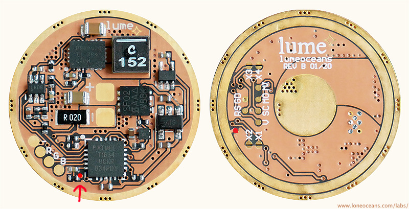
Using this image posted previously by another member: on the spring side, you can cut the trace going from the ring to the via (red dot) to prevent shorting out the e-switch ring contact. You can do this with a sharp penknife and cut the short trace between the via and the ring. Verify that the trace is indeed cut; some magnification would be useful.
Then, on the LED side, you can connect the E-switch by soldering onto the right side of the black resistor (where the red dot is), and the other contact should go to ground. You can use the (-) pad of the Aux LEDs. Let us know how it goes!
Hmmmmm. It will be challenging but I Aced the solder job on the Lume1 and aux board combo. If it doesn’t work, I’ll just pop the Lume1 into one of my other two FW3A’s. Now I just have to wait for payday.
Is anyone experiencing erratic turbo step down behavior? I set the Lume1 in my FW3C to 65 deg C and I noticed the following:
1. When turbo starts going down in steps (very visible), a double click takes it back to the top of the ramp, then I have to double click again to get full turbo. On the FET+N7135 driver double click jumps straight to turbo. If I let the Lume1 step down for longer, maybe about 30-40 seconds or so, double click jumps straight to full turbo. There’s no clear indication when the step down from turbo enters the ramp, so I never really know if one double click, or a second double click will get it into turbo.
2. When the light is at ambient temp. and I go to turbo, it steps down within 10 - 20 seconds just as my finger starts feeling the heat. But it’s mild and not uncomfortable to hold. An immediate second bump to turbo will do the same, but obviously now the light is hotter, slightly uncomfortable to hold, but far from unbearable. An immediate third bump to turbo lasts 2 - 3 times as long and then I can barely hold the light at the tail between my fingers. This varies a lot and sometimes happens on the fourth turbo run.
 w/ stock FET+Linear driver @ top of ramp (~3A) - new firmware")
 @ 17W setting")