Does anyone have pictures of a M43 Switch PCB they could share?
Front and back would be great but anything might help me figure this thing out.
Anyone?
I can’t for the life of me figure out how blue is supposed to work.
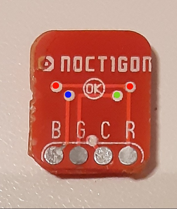
B is only wired to the right side of the switch.
R is wired to Both Red and Blue LED+.
When power is applied to B&C nothing happens because it’s not a complete circuit.
When power is applied to R&C the Red LEDs illuminate.
If I remove the RED LEDs and connect power to R&C the Blue LEDs illuminate.
Front(Switch removed):

Back:
LED- Path:
