Mini-review: Noctigon M44

All of my DM11 with the boost driver flicker at level 1/150. Now I am curious to test for PWM at a few levels above where flickering is no longer visible.

Does the M44 still exhibit “high risk” pwm a few levels up from 1/150?

edit:
I tested the PWM on lowest modes across several lights, also including the M43.

Green safe zone:
Zebralight Sc700fd
Armytek Wizard C1 Pro
Fireflies e07x
Noctigon M43

Yellow zone:
Zebralight sc600w plus Hi

Red zone:
-DM11 B35AM ( at low and even medium ramp)
-Jetbeam jetu AAA

1 Thank

Thank you so much for detailed review and for spending time with us

If I’m reading those graphs correctly, it looks like it’s showing ripple of some sort, which is different than PWM. A PWM signal should read as 100% modulation, turning completely off and on during each cycle, like a fast strobe light.

Here’s an example of PWM. This light was using PWM at 488 Hz, and I waved a thin white object through the beam while taking a picture. It gives the appearance of having distinct “frames”, like a series of pictures stacked:

This is how that type of low-mode PWM looks on a scope: (not my picture)

Here’s what I see on the M44. It’s hard to get a good picture, but the oscillations are a ripple instead of a full on/off pulse. This produces a motion-blur effect with a repeating pattern instead of distinct “frames”:

It may be possible to reduce the ripple effect by speeding up the pulses the MCU sends to the lowpass filter, but this will likely mean slightly brighter low modes and a harder time getting the ramp to look smooth. It also won’t help much on the lowest modes if there are other sources of noise, like if the regulator itself isn’t steady. If it’s like several other regulated drivers I’ve encountered, the MCU could send a solid “zero” signal and it would still be unstable … because the regulator simply doesn’t have sufficient resolution. The moon level and pattern are typically defined by the regulator’s noise floor.

Anyway, what I find to be the easiest way to gauge this stuff is … what I showed it the pictures. Find a thin white sheet of some sort, and wave it through the beam very very quickly, with a dark background. This is a cheap, quick, low-tech way to see the pattern and speed of oscillations in a light source.

10 Thanks

Thanks for the great review :+1:

What do you mean by audible PWM? did the M44 make any noise?

I have a NOV-Mu Fireflies and sometimes it hits my nerve with a high pitched noise.

Really interesting. Here I was thinking “well, guess I need an oscilloscope” :rofl:

If I hold it up against my ear, I can hear PWM on some mid and high ramp settings, but not at hand’s distance or any other realistic usage scenario.

2 Thanks

Yes! You totally own this review! Great and very insightful!

A small rundown on visual/audible artefacts and their causes so that they can be better identified.

Low frequency PWM dimming :
LEDs can be dimmed in two ways, either by lowering the drive current, that’s analog dimming, or by rapidly turning the LED ON and Off, that’s PWM dimming.
PWM dimming can be visible when the switching frequency is too low, below 100~300Hz depending on people, even when not clearly visible it can be uncomfortable. The solutions are to use higher frequency PWM or analog dimming.
PWM dimming can produce audible noise when the switching frequency is in the audible range, up to 16~20kHz. The components that generates the noise are usually MLCCs (multilayer ceramic capacitors) and sometimes inductors (coils). The solutions are to not use noise generating components, use >16~20kHz PWM or analog dimming.

Regulator instability :
Due to various reasons, the regulator can be unstable, for example not enough input/output capacitance, inadequate compensation (for the regulator feedback loop or constant current regulation feedback loop).
In the case of the Nov-mu (or others FF model before the new 2022 drivers) mentionned by @tiry31 above, it is not enough input capacitance, in combination with higher impedance/DCIR (lower current/older) cells, the output can be unstable and oscillate, when the oscillations frequency is in the audible range and large enough, the MLCCs and/or inductor generates audible noise.
This usually happens at medium to high output, rarely at low output. The oscillations being nearly always at highish frequencies this will not generate visual artefacts.
Solution : hardware fix.

Regulator low switching frequency :
To save power, a boost/buck regulator can decrease its switching frequency at light loads, from 200-2500kHz it can go as low as tens of Hz at extremely low output.
In the audible range the MLCCs/inductor can generate audible noise, although high frequency regulators that are able to do very short pulses will usually not make the MLCC generate noise, boost converters seem worse than buck in that regard.
At too low frequency it can be visible.

Solutions are mostly hardware : not use a light load efficiency mode (but then high current draw at low output), add a resistor load in parallel to the LED to prevent the switching frequency going too low (for flickering), use an Ultrasonic mode when the IC is capable…

Low frequency PWM control signal passing to the output :
This is the effect mentionned by @ToyKeeper above.
With analog dimming, the constant current regulator will usually be controlled by a voltage signal, a certain voltage will produce a certain current, half of that voltage half of that current… etc.
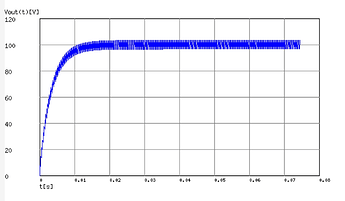
A microcontroller being digital must convert the digital signal to analog, ideally with a Digital to Analog Converter (DAC), but when there is no DAC or we want more resolution then a PWM signal that is smoothed out with a Low Pass Filter (LFP) can be used, this is what most flashlight driver do. The result is an ”analog” signal with a ripple voltage, for example with the Noctigon linear driver values at 4kHz (before dynamic PWM)


(Nevermind the voltage, I put 100V so that we can reason in %)

The ripple voltage at low duty cycle is about 8%, which translates to 8% current ripple.
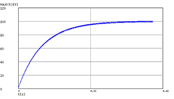
With dynamic PWM the maximum frequency is 16kHz :


Ripple is reduced to ~2%
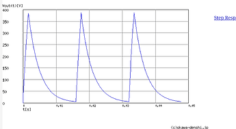
But for low lows, the resolution is increased and the PWM frequency decreases to 61Hz (? with 16bits for 2ch ?) At minimum :

Not enough filtering anymore (400ish % ripple) because the pulses are too spaced out and at 61Hz this will look quite flickery.

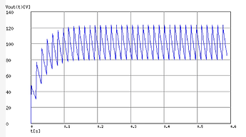
One solution (hardware) is too increase the strength of the LPF, for example by 10times :


Now the ripple is about 40%, which at low output might be sufficiently low to not be visible. The side effect is that the rise/fall time is longer, if you noticed it took about 10ms before to reach the target voltage/current, now it takes 100ms. This mostly affects strobe modes as they are now not able to turn the LED ON and OFF quick enough.

Electronic noise at very low sense voltages:
A constant current driver will regulate the current by sensing the voltage across a current sense resisor, with Ohm’s law Vsense=Iout×Rsense.
Still using the Noctigon linear drivers example Rsense=10mR, (max) Vsense=50mV, thus Iout=Vsense/Rsense=50/10=5A.
This Vsense is compared with an Operational Amplifier to the control signal, also 50mV, that’s how we control the output. At these voltages all is well, but as we reduce the control signal to dim the light to very low output, the sense and control voltages becomes proportionally very low and around 100-50uV (500-1000 times lower) circuit noise starts to become relatively important and so the output will be noisy, more so in noisier boost/buck drivers. This looks kind of like Anduril candle mode.

10 Thanks

Why not use fast PWM instead of phase correct ? That would double the PWM frequency.
Phase correct makes sense in a FET driver because ideally we want to stop switching in turbo for lower losses, but even then it might not be really that important.
With a constant current driver not being able to do 100% duty cycle is not a problem, since the current is adjusted arbitrarily in hardware, one would just set it so that 254/255= 2A (255 would be 2.008A).
But even if the current can’t be adjusted now in hardware, 254/255 is 1.992A, really not that much different from 2A.

Unless of course phase correct is needed for dynamic PWM ?

1 Thank

Really interesting, understood more of that than I thought I would, got to take a look at the source again now :slight_smile: some of the more complex PWM code didn’t really always make sense before.

1 Thank

Flood/throw video. The throw on this light is actually really impressive - I guess the simple fact that there are 8 W1s together overcomes the somewhat floody optics.

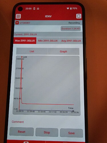
Also, preview of some data gathering in progress to keep everyone excited:


A lot of people, including myself, were seeing the M44 as a D18 replacement - an enthusiast light with some extremely high power, but more modern with aux LEDs and flashing pads. When it was revealed to be a horizontal scaling of the existing 2A/LED boost driver, I will admit I was mildly disappointed, but still excited because there is still nothing else like it that exists.

When the details came out that it was a 2A/LED boost driver, I personaly felt it wouldn’t work that well as a flood/throw light due to how shallow the DT8 optics are. With an M44 in my hand, I can say that the throw is excellent - yes, my DM1.12s are lighter, smaller, and throw further, but the M44 puts out way more lumens, and throws almost as far.

When I went to test the throw on the W1 outside at night, I was amazed. It’s a lot throwier than I thought. I guess, the W1 is an efficient LED at lower currents, so 2A means the W1 is still being driven at a reasonable level, while LEDs like 519A or W2 that can take higher currents are closer to the bottom of their operating window. That, plus the simple fact that there are eight of them, makes this actually a great thrower in my opinion. Sure, you can get more throw for the dollar, but with the flood channel too and the extremely high efficiency, it’s a unique combination.

On a more personal note:

I’ve been going through a very difficult time in my life recently, and all of this happened relatively unexpectedly for me, that I would be possibly the first person to get her M44s, and my decision to do a review at all was impulsive and a way to distract myself from some bad things that were going on in my life, but I’ve really enjoyed everything and this community has made me feel welcome. Certain community members, in particular @ToyKeeper herself, have really gone above and beyond in making me feel welcome - I know I’ve been here for a short time in comparison to some people, but I tend to be passionate about things I like (in less than a year I went from buying my first new light to finding and fixing bugs in anduril, after all… :P), and it makes me happy to know other people out there are getting happiness from my work too.

I want to thank everyone, and I hope that I can keep being helpful to a community that has given me light (literal and metaphorical) in a very dark time in my life, and I feel glad I can bring that same light to other people’s, whether with an impulsive unscripted unprofessional review, firmware mods, or just giving advice. Sometimes this community has been a reason for me to keep going. Thank you.

15 Thanks

I’m glad we have you as a part of this community!!!
Great review! That is onenthing I love about the community, no bs, all love!

4 Thanks

Runtime testing done!

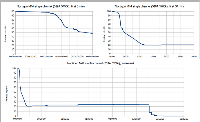
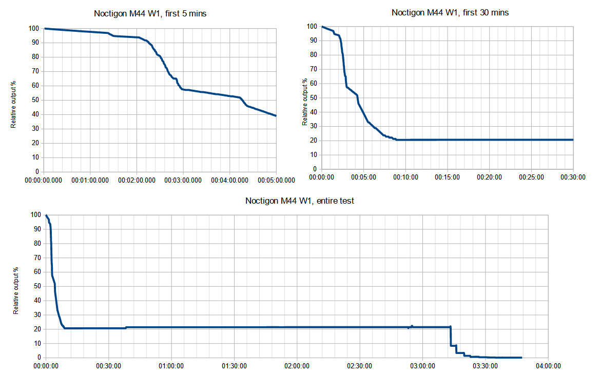
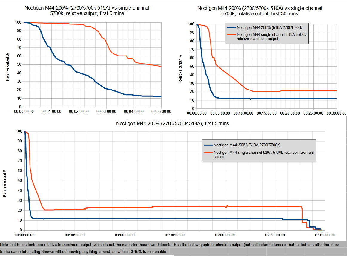
All measurements with a UNI-T UT383BT in the world-renowned (people in more than one country have heard of it) Integrating Shower. I don’t have a tube or sphere or any way to calibrate output, so these tests are all relative to 100% output. Using 3x Molicel P28A charged to 100% for each test.

Runtime was very close to the same with all LEDs (which makes sense for a 2A/LED boost driver), so not all combinations were tested (I did test thermal stepdown with each different 519A channel and compared to some other lights I own just to validate my test setup but stopped the test at the stable level). I did test 200% (turbo in the ‘both’ channel mode) but got the same runtime as with a single channel active, which seems to be incorrect, but I need to check the source code and probably do another test run before I’m sure. I also haven’t updated my M44s to the latest firmware version, and the one they shipped with is somewhat old (2022-05-30) - I don’t think there would be changes that affect it, but I haven’t looked at the history yet - I’m oncall this week so a bit busy even for background tasks.

Anyway, the data:


The difference between these results is within an acceptable margin of error, so at least for most LEDs, the M44 is not substantially different in thermal or runtime performance (which makes sense with 2A/LED).

3 Thanks

What firmware is on that? That’s not how mine behaves.

As a sanity check, I did a quick measurement just now. My cells are only about half full, but here’s what I measured on turbo:

  • Channel mode 3 (both): 7130 lm
  • Channel mode 4 (manual blend): 4330 lm

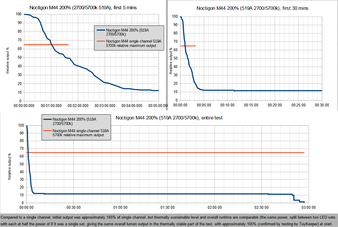
If the manual blend mode can be considered 100%, the “both” mode gave me about 165% as many lumens… and it should reach near 200% with full batteries. Not exactly 200%, since 2X power doesn’t mean 2X lumens, but it should at least be close.

I finally remembered to upload the M44’s code today, if you want to see how it works. The “both” mode goes up to 100% power on each channel at the same time, for a total of 200%… while the “manual blend” mode divides 100% between 2 channels (to keep power steady while changing tint, and to keep tint steady while changing power).

2 Thanks

2022-05-30. Haven’t looked at the config since you pushed it yet, but it is possible I screwed up somehow and accidentally used ramping mode or something (I tested I was in the right mode by checking 3H went to turbo before starting the test, but it took me about 8 attempts to get 3 good full runs due to various mistakes. I forgot to start datalogging before the test twice :rofl:, and on my first attempt I didn’t notice there was a time limit on the datalogging by default so it stopped really early ). I need to charge some batteries back up but I’ll pull the 200% result until I know.

In terms of absolute output, battery charge shouldn’t matter until it starts to get reallly low on a boost driver - if I stopped a runtime test at the sustainable level, let the light cool, then restarted, it should be able to get the same initial output figures.

1 Thank

Wolfgirl, I’m sorry to hear that you’ve been going through such a hard time, but I’m glad you were able to find a glimmer of light here to help get you through it. Darksucks
I hope you stay around, I love reading the advances that have been going on with the new developments in Anduril.

Best regards, Bob.

2 Thanks

Great work, thanks!
Why does the last graph (whole runtime) show a drop to 10% while the others show a drop to 20% only?

Edit: incorrect assumption by me, see next post

Thanks. Don’t worry, I’m here for the long term, and paying forward a bit of that happiness I’ve felt is one of my favourite ways to pass the time.

2 Thanks

I mean the titles of the graphs may be wrong then. W1 30min shows a drop to 20%, while W1 full test shows a drop to ~11% at the 30min mark. This appears contradictory.à
EDIT: It’s all corrected now! Thanks!

1 Thank

Edit: Got a chance to take a look at the M44-specific code, and it definitely does support 200%. My guess is I was accidentally in tint ramp mode or something :person_facepalming: - I’ll do another runtime test for actual 200% later.

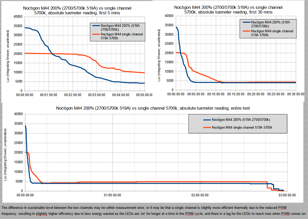
Edit: Tested with my W1/519A M44 (because it was the one of the two with charged batteries) and yes, both channel mode does go to 200%, there is a noticeable increase in output as measured with my luxmeter, but I completely overlooked one thing: it would still thermal throttle down to the same level, with the same power consumption and heat generation!. I guess I need to do some testing with actual repeatable max levels, haha.

Updated runtime testing:


The difference between these results is within an acceptable margin of error, so at least for most LEDs, the M44 is not substantially different in thermal or runtime performance (which makes sense with 2A/LED).

It is worth noting that I do not have a lumen tube or integrating sphere (yet?..), so I can not measure absolute output. The 200% turbo on the 519A reaches the same runtime as the single channel 519A because it still has the same thermally sustainable level - the initial output is higher (@ToyKeeper measured 165% overall output, which is close to what I got with my uncalibrated luxmeter), but it steps down to the same actual power level, just split between two LED sets). As soon as my lighs cool down from testing, I’ll do some relative luxmeter comparisons.

Here are some quick and dirty luxmeter measurments on turbo (distance between light and meter is 1m):

W1: 73,611 lux
519A 5000k: 16,962 lux
W1/519A 5000k 200%: 87, 659 lux
519A 5700k: 17,033 lux
519A 2700k: 11, 848 lux
519A 5700/2700k 200%: 28,669 lux

Figured it out (as soon as I started doing something else, as always…) it’s because the relative maximum is not the same, and at first I assumed it had to be because the runtime was, which in hindsight doesn’t make any sense at all (guess my brain was still calibrated for FET lights :rofl:).

5 Thanks

Hi wolfgirl, hope things take a better turn for you soon and I’m glad you’re finding some comfort in this community. Thank you for your enthusiasm, which in this case has been the final convincing factor for me to order an M44 if you’re keeping a tally :sparkles:

2 Thanks