Mod - TK75 with HX-1175b1 at 16.8 volts - Pic Heavy

Summary:

  • 16.8 Volts (2P4S)
  • Attiny13a swap with JonnyC's Star Momentary modded by Tom E for strobe:
    • PWM's 1,3,9,27,81,125,255
    • 90 second turbo time out
    • LVP
  • Momentary switch that bypasses MCU for full power:
    • Can be used while any mode is on to create unique signals.
    • Can be used if desperate and LVP is not letting light work
  • Lock-out switch installed
  • 7 amps per emitter. Yay!

Saw that a new TK75 is coming out. Sounds great. Big head (but still reasonable sized for jacket pocket carry), light weight for size, shallow reflector for wide spill, and 4 emitters (the perfect amount and beam pattern). I want one but don't have the bucks for one. So I looked at mine and decided it's time to upgrade. Liked what RacerR86 did here. Based on that mod, it appears the TK75 has hardy XM-L2's.

I've been wondering how the HX-1175b1 driver would do with 3S hardy XM-L2's and 4S cells. Buck drivers generally have less ripple if the load's Vf is near the input voltage. 3 XM-L2's in series should be able to absorb more ripple than 1S or 2S. Since the TK75 has a neat thick copper emitter base and great thermal path, I had no choice but to go that direction. RMM has a nice TK61/75 driver option here.

Another thing most lights don't have is a way to manually signal. This light has 2 momentary switches. So one will bypass the MCU and feed VCC directly to the buck converter pin that is feed PWM.

I haven't seen many good tear down pics. So I tried to squeeze in a few here, but also tried to not take pictures that would be redundant to RacerR86's thread. So here goes.

Top of Head:

Not much to do here. The integrated shelf is nicely finished and flat. Also, the leads are thick and short.. Only things that bothered me was a very rough finish to the bottom of the emitter base and not enough thermal paste. So Lapping, more paste is all was done up here.

Driver:

Cavity:

There is not enough vertical space for the driver in its stock form, but there is plenty of air space in the plastic spacer to relocate the large inductor. Used copper sheet to make an adapter plate.

Low Voltage Proction. 100K R1, 5.1K R2.

MCU and Momentary Switches. Put an Attiny13a on one of wight's OSH Park adapter boards just to protect the pins. PWM has to be soldered directly to the pin though. Used Star Momentary with Tom E's strobe mod. PWM's 1,3,9,27,81,125,255. Will be tuning the turbo timeout and LVP based on results from usage. When I get happy with the settings, I will report them.

Connection to battery carrier contact plate.

Needed a way to deal with parasitic drain. Used an old Judco switch that has been in several lights. Used an RCA jack center post for a plunger and some thick grease for water resistance. Would like to change this in the future to be water proof.

Battery Carrier:

Used 2 carriers to create a 2P4S configuration. Each individual bank of 2 cells is connected in parallel so that they remain in balance with each other. The carriers will be permanently connected as neither will work alone and one only a top and the other only a bottom.. The mod will involve the following:

  • All carriers:
    • Remove all brass rods (2 per carrier).
  • Bottom carriers:
    • Bridge positive cell contact pads to each other.
    • Bridge negative cell contact pads to each other.
  • Bottom PCB of Top carrier:
    • Remove diodes. This will disconnect the positive to negative path.
    • Connect the positive cell contact pads to the nearest side post (formerly a negative brass rod contact point).
    • Connect the negative cell contact pads to the nearest side post (formerly a positive brass rod contact point).

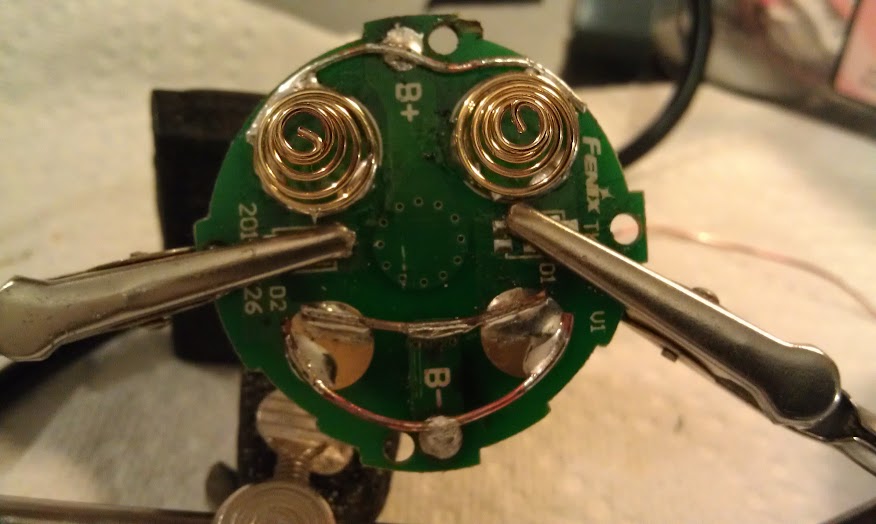
Some stuff inside the carrier.

Here is modded Bottom PCV of Top Carrier.

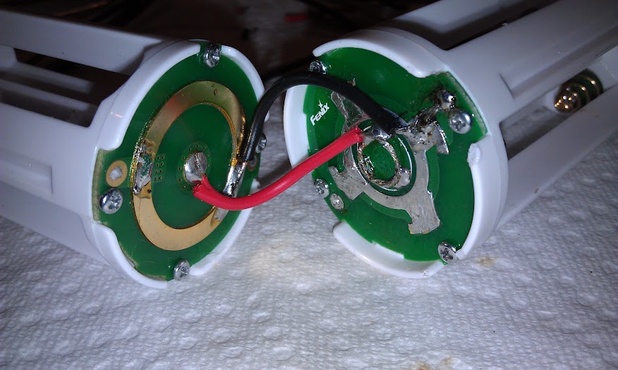
Here is Bottom PCB of Bottom Carrier. Just joined parallel cells. The Top PCB's are already joined in the stock PCB.

Beams Shots:

Before, Mouse over is after. After was taken aft rain with high humidity. So moisture in the air absorbed some of the light.

Conclusion:

Mas brighter and lots of mode options now. Miss the variable strobe though. The emitters seem fine at 7 amps. The MCU by-pass switch really increases the range of things the light can do. There is audible hum in modes 4, 5, 6. Mode 6 is by far the loudest. Potting the MCU should help, but would like to figure out how to resolve with FW first.

7 amps per emitter? Isn’t that like xhp70 territory? That’s going to give those xml2 s a serious work out lol!

I cheated and stuck a TK-seis-um in mine, but I didn't even try for 7A because I didn't think the emitters would do it, so I settled for 6A and am happy with. You've got some good 'ol ones if it is running at 7A! Lucky dog. Hardest part for me was "fixing" the carrier.

Man, I'm a ditz. When I did this, I totally forgot about your driver RMM. That should be a much better option. I probably would have still went this route because I already have several HX-1175b1's and money is a bit tight right now. I wish I had considered it though. That driver sounds real good.

light junkie wrote:

7 amps per emitter? Isn’t that like xhp70 territory? That’s going to give those xml2 s a serious work out lol!

I would say better as this set up will get more throw. An XHP70 at 7 amps would be 4 dies at 3.5 amps if set up for 6 volts. This light is 3 dies at 7 amps each. So you would have to run an XHP70 at around 11 amps to get equivalent wattage consumption. You would then get more lumens, but still less throw.

However . . . Depending on the beam profile and such, I may go one XHP70 and 2 dedomed XPL's (Parallel to each other, but both feeding the XHP70 in series) at 12 amps. That would be 6 dies at 6 amps each. Would need a short turbo time out, but I don't use high much at all. My wife on the other hand doesn't seem to believe in any other modes than high and strobe.

Your solution makes for a way cooler thread though!

Thanks RMM. Much appreciated bro. :)

Was a bad night atmosphere wise for beam shots, but took some anyway and added to OP.

Wanted to include video of manual signalling with the light in a low mode, but I can't get the video to work. I will try again later.

Tough crowd. Seemed like some ideas in this thread would be of interest to modders that could be used in other lights. Ideas such as:

  • The HX-1175b1 can be used to drive 3S XM-L2's (old hardy ones) to at least 7 amps.
  • HX-1175b1 mod ideas to make it physically fit in different lights.
  • An alternative use for duel momentary switches that allows one to create what ever manual signals they can imagine when combined with FW modes
  • Some good inside info on the TK75 for folks interested in the light and mod ideas such as:
    • Battery carrier mod for 2P4S where the individual S's are paralleled for more safety.
    • Lock out switch location idea

EDIT: Thought on newer XM-L2 that fail below 6 amps. I wonder if something was changed in the bottom pad connection material. I notice that mine all seem to have a more pronounced oxidation circle than in the past. It covers a good portion of the thermal pad. Obviously, solder will not stick well to the oxidation and it will also restrict the thermal path in and of itself. I remove the oxidation with 2000 grit wet sandpaper. I hope to check this idea out soon and am really hoping it is the cause of the failures.

I wonder, doing a mod similar to this, if it would be possible to drive 3x XHP70s?

I figure you’d have to grind or drill out the bottom of the reflector to accomodate the larger size, but you could easily get 12K lumens, right?

I was thinking about doing this on an Acebeam X60M, but I already have a TK75 3x XM-L2 with a second battery carrier and extension tube, and Acebeam isn’t extending a BLF discount anymore.

^ That would make one heck of a light. I think it's an awesome idea.

The reflector holes are large and will clear the XHP70 by a good margin. The hard part would be keeping the reflector from shorting on the emitter bases and clearing the leads. The shorting problem can be solved by lightly sanding off the metalized finish on the back of the reflector. If the wire leads don't clear the reflector, you could probably use copper tape/foil to make a low profile connection in the place of lead wires connected to the base.

You would need to run the emitters parallel in 6 volt configuration. I've pushed the HX-1175b1 to 12 amps and it may be able to go a little higher if you heat sink the driver well. I don't know what RMM's TK-seis-um driver is capable of current wise, but it sure would be easier to install.

Best wishes if you do the mod. Please create a thread on it if you do. I would love to see it.

EDIT: You might want to consider going with one XHP70 and then have 2 xml/xpl's in parallel feed the XHP70. So it would be equivalent to 2 parallel runs of 3S xml's. That should probably give you all the flood you could use and still have throw. Would be way easier to drive hard too.

EDIT2: Sorry for not replying to your question about lumen output. I don't know the answer to that. Guess you would have to decide what current you would feed the emitters, divide that by 3, and then look up lumen output chart and multiply that by 3.

:open_mouth: Amazing mod congratulations! H)

How many kcds with this configuration? is dedomed? or dome on?

Thanks!

Thank you gaston01.

I took a quick throw measurement yesterday and was disappointed that it was only 180kcd. I have the domes on. RaceR86 got 206kcd (I think) at 6.6 amps per emitter. I need to make sure my light meter's battery still has enough voltage. I've been using it for years and it still has the same cell. 180kcd doesn't sound unreasonable. I'm just hoping there is a measurement issue and that it is higher.

So is there a way to push 21 amps? I don’t think RMM’s driver can do that much.

Divided by 3, that’s 7 amps per, and at 7 amps that’s a little over 4500 lumens each according to THIS post.

16.5A would still get over 4K lumens per.

Or am I dense and you could run them in series supplying 7A? Scratch that, I’d have to get nearly 20V to the emitters to do that. Could do, 8S1P…. :smiley: :stuck_out_tongue:

EDIT - Vinh has his TK75vn70 up an running, so it’s possible to drive them. But can they be driven to 4K lumen or more each?

^You, my friend, seem a bit of a mad man. My flashlights would run from you in fear.

You may want to consider DD. XHP70's configured for 12v can be driven by 4 cells theoretically. This thread here started to talking about it.

I remember what Vinh did. 1 driver for each LED, this would give plenty of amps. And I could run 2S2P / 2S4P leaving the carriers unmodified maybe.

Now to figure out what driver. The FET+7135 looks promising…

Sorry for derailing your build thread - you gave me a lot of inspiration and a LOT to think about! :slight_smile:

No prob. Ideas like you're thinking about is the most interesting stuff. You have me thinking now too, but smaller. I'm thinking the XHP50 would fit on the stock TK75 base without modifying except for traces.

3 Drivers? Hmmm, I have no idea how to pull that off at the moment, but I like the way that sounds.

Here’s what Vinh got back in March for both of our ideas:

(pulled from his Lounge thread on CPF)

Fenix Tk75vn70 XHP70
Sony vtc5
10,282@ turn on
9082@ 30sec
4528 high
328 mid
38 low
Throw - 107,000 Lux

Fenix Tk75vn50 XHP50
Sony vtc5
8299@ turn on
7699@ 30sec
2949 high
101 mid
18 low
Throw - 138,000 Lux

7699 is still crazy bright, especially given the lux. Hmm, XHP70 or XHP50? And if you instead modded a new 4xXM-L2 TK75 or TM16…. :smiley: :slight_smile: :smiley: Heat might be an issue, but 4x XHP50s driven to 7-8K lumens should, in theory, be more efficient, no?

There's no reason to use a buck driver for XHPs...too many watts and the batteries line up just right for 3P XHP emitters in 12V (4S input).

Would the Seis Um driver not work with 6V XHP70s in parallel with the cells in 2S input configuration? Or would the amp draw be too high?
Sorry for the noob questions, I’m learning.

EDIT - yes, I’m a noob. Seis Um has a ~10A limit, trying to drive 12-15A wouldn’t work. It might (if I read right) be okay to drive at ~3.3A per emitter, but that’s it.

^ With a buck driver, you really need some voltage overhead for the driver to work properly. So you would need at least 3 cells for proper regulation of XHP50/70 in 6V configuration.

Just like with RMM's example of 4S cells for 12 volt config, 2S cells for 6 volt config would be best driven direct drive ("DD" as I referred to it above). Plus with DD, your current is only limited by what the cells can deliver in any particular light. You will have less regulated run time, but more usable run time due to the efficiency. I don't know about Seis Um, but buck drivers are in generally 80% or less efficient.

When I said you had me thinking now too, I was playing with the idea of one XHP50 and 2 dedomed XM-L2's all in series going DD with my 2P4S setup. I like this idea because I'm don't really want to modify the reflector or base at this time.