I posted this on Reddit a few days ago and was told I should show it off here. This project was inspired by a Reddit post of someone taking measurements of the LED and I thought, why not.
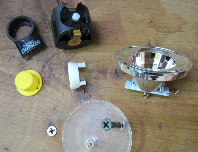
I purchased it for way too much on Amazon and immediately tore it apart after receiving it. The first to go was the cheap PC lens - it wasn’t very optically clear anyways so all I used was a pinvise to make a small hole in it and stick some pliers through it to wrench it out. Unfortunately as it was designed so that the plastic lens would sit under a lip in the head, a glass lens of the same size would not fit. Only a lens larger or smaller than the stock one could be used and it would have to be glued on if it were to look nice. The body is made of thin walled aluminium tube with the head area drawn out before milling (the insides weren’t deburred and it took a blood sacrifice during further disassembly). The dinky 1W LED it came with was mounted on a strip of FR4 and screwed in to the back of the plastic reflector, so those couldn’t be used either. in fact, everything apart from the metal tube and tailcap was discarded, as it turned out the reaction force of the lip was the only thing preventing the battery spring from sending the insides of the light out the front.
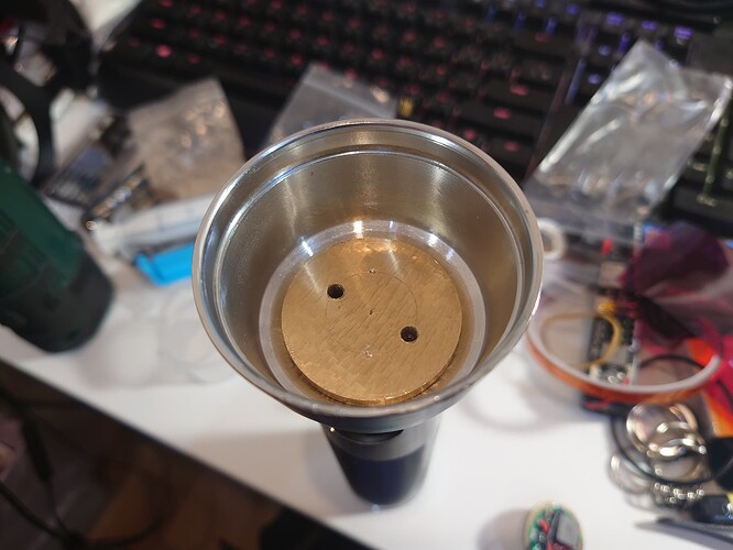
There wasn’t much thought as to what LED I was going to put in it, I happened to have a couple spare XHP70.3 already on an MCPCB so I decided it would probably work if I gave it enough thermal mass. This resulted in a bit of researching materials before I settled on some 38mm brass round stock which a chunk of would fit in the head in the area joining the battery tube area (the tube was 32mm in diameter for D cells so the brass pill/shelf would have to be machined down)
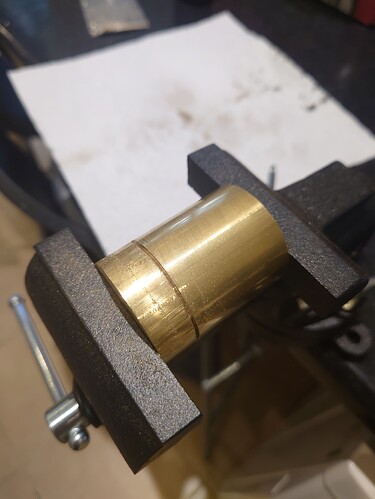
To fit the pill in the tube part of it had to be machined down to 32mm diameter, and I chose to use a 3mm cylindrical carbide burr but with a knockoff dremel because I didn’t have access to a lathe:
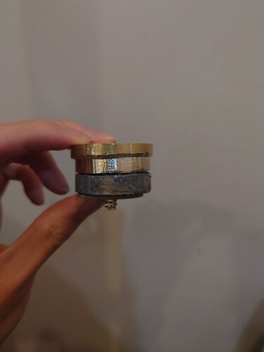
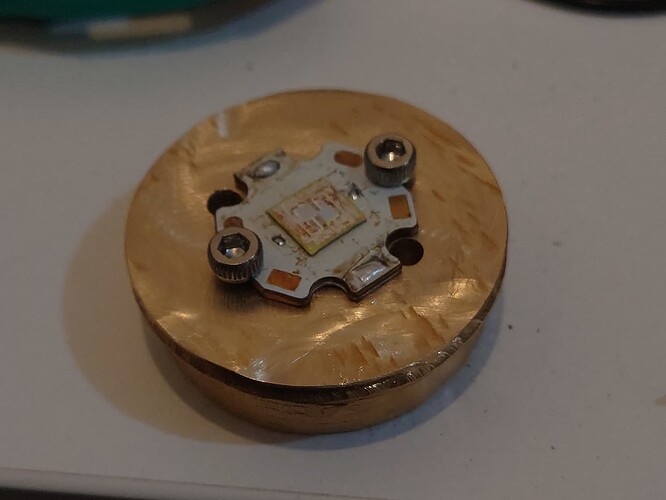
A spacer made of metal epoxy was also produced, but it was not electrically conductive and I did not consider how I was meant to ground the driver yet, causing some interesting design choices down the line. Holes were also drilled in the pill, 2 for wires and aother 2 which were tapped with an M3 thread to screw down the MCPCB. I found out the hard way that freehand tapping isn’t the easiest thing in brass and resulted in a self-stripping tap for half the depth of the hole:
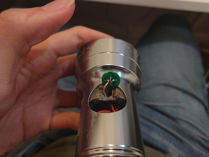
Next was a test fit with the driver - this is when I realised that I needed a hole in the side of the spacer for the e-switch. The driver used was the Convoy 6V8A L6 buck driver:
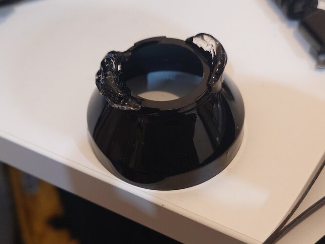
Now for the optic - I prety much just looked for one that just about fit the weird internal dimensions of the head which resulted in me choosing the LEDiL Carmen 50. It needed to be modified to focus the beam correctly but that could be done with some crude additive mnufacturing using UV epoxy and a file:
Once I got everything to fit, some metal epoxy was applied around the pill for it to be permnently mounted to the host and prevent the battery spring from sending everything out the front. Some more cursed design choices were made, such as simply soldering a thick wire between the driver and tailswitch to ground it, and a janky frame made of cardboard and UV resin to keep the 26650s aligned in the tube and allow space for said ground wire. I also decided to use the original switch retaining ring which was moulded to fit that hole exactly to make it look closer to original, so some metal epoxy was used as an adapter.
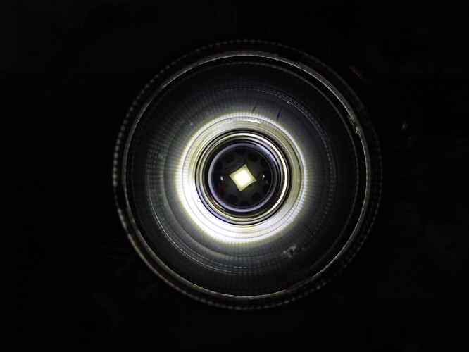
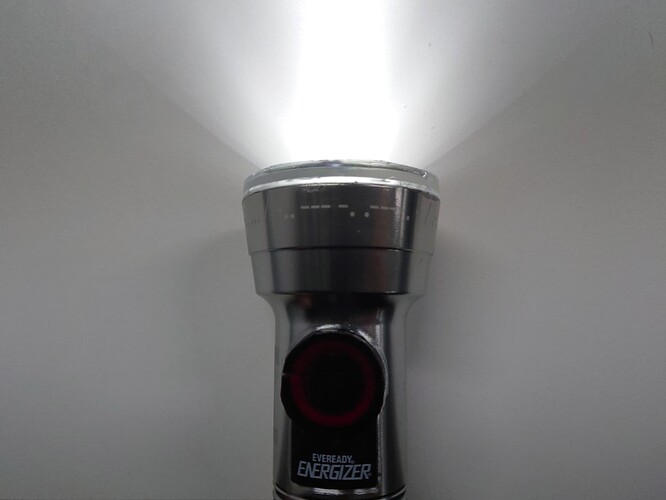
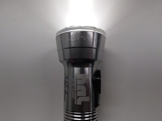
Completed torch pics:
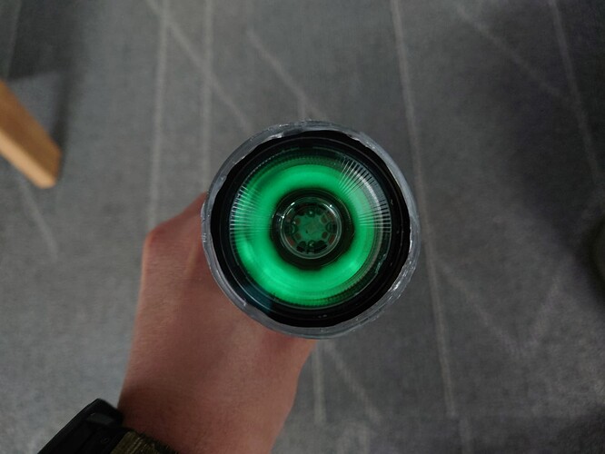
And added a bit of glow powder mixed with the UV resin under the TIR because why the hell not.
Edit: Fixed image dimensions because I’m bad at maths
