The automotive bulbs don’t mean that it’s not 18vac system. Hot wire bulbs work regardless of current feed to them. I regularly hook up 120vac bulbs to my 98vdc solar array. Drives them great. No regulator need for traditional bulbs because they provide the resistance themselves.
Why go through all the trouble and expense of using separate LED drivers and a buck converter? The unit I linked to does both. It is a buck converter with the ability to do constant current output.
It is a nice sullution, that’s for sure!
Since he already has the drivers and needs to add a rectifier & cap to this unit, trouble and expense are quite comparable I guess.
Your suggestion yields the opportunity to drive the LEDs quite hard if desired tho.
(But I guess in a watertight case one still would need a creative sullution for cooling)
I will consider your option if I need to drive the LEDs harder.
-Garry
I’ll continue following this…
I have a ’72 Elan (pull start, no battery) so if I go to an LED headlight I’ll probably need a similar solution.
It’s not that interesting of an option anymore, but since this converter is just under 2$ shipped I figured I could as well test the little thing anyway.
I testet it with an 12V halogen lamp that draws 1.5A at 12V.

Input: 24.6V

Output: 1.5A at 12.1V

Results: well, the whole board heated up within seconds. I was unable to hold the board for more than a few seconds.
Unfortunately someone took the temp probe, so I have no measurements on that.
Not that big of an suprise. 22.05W in, 18.15W out makes 82.4% efficiency, but the 4W still have to go somewhere. Difficult on a board you could put into a matchbox
I liftet the chip and clamped a heatsink on it very professionaly (:P) to test how much heat the other components contribute

Heatsink gets now really nice warm and you can hold the board. Inductor and diode still get hot, I would estimate ~50°C, but that should not be a problem. Input cap is in direct contact with the heatsink and gets hot, but since it’s no low-esr type it may without that too.
I will leave it on until tonight when I go home, but I already can say that I would not recommend it for use in a confined space. There is no use for a converter that eventually will go into thermal shutdown after some use. This is probalby also true for the more or less similar converters linked in this thread. With a heatsink and some moving air it will probably do fine tho. Nothing wrong with the board operating at 60°C or so.
I really would not want to operate it on higher power levels.
I will bring a second lamp the next days to see what comes first: thermal shutdown or self destruction.
But it’s a national holiday today and I am quite alone here. Don’t want to trigger the fire alarm without anyone to tell it was a false alarm. ![]()
Thanks for the info! It doesn't help that in my situation the engine's exhaust is right under the headlights (so it gets hot up front there). If used in my situation I'd likely have to mount it further away and run longer wires to the lights (not that bad to do, although I was trying to avoid it). I had already figured the boards like these need a heatsink added.
-Garry
Nice work dave_. Great pictures too.
Thanks!
I guess pictures weren’t really necessary. On the other hand, people can see than what one did and maybe spot an error.
Btw: output voltage ripple in this configuration as almost 200mV at 57kHz. One would have to make sure any following regulators can take that without going berzerk or add better output/input filtering.
I still think the Super Simple DIY driver solution is the best though. Since you wouldn’t be running the lights on battery power only (just 12 volts), you could go 4 xml’s in series (2 per side). Imagine that, a lawn mower with 4 xml’s driven at 3 amps each.
EDIT: You would need to hook directly up to the battery. But the voltage would be higher with the engine running.
He would have his ‘respectable’ light output for sure. ![]()
hahaha awesome thread! ![]()
Thanks dave_
texaspyro, is this the same but without the fancy led controls?
www.ebay.com/itm/DC-5A-0-8V-30V-Constant-Current-Voltage-LED-Driver-Step-Down-Power-Module-new-/121108371961
Possibly… but it does not have the heatsink and may not be able to handle as much power. They don’t say what switcher chip that they use, and there are usually some hidden gotchas on just what the allowable range of input/output voltages and currents that they can handle.
Wow! Today I received the "AC DC 24V to DC 12V Converter Power Supply Voltage Regulator Waterproof Module" I ordered on May 2nd! Came China Post. Tracking never updated (still says processed through a sort facility in China). EDIT - This was my fault. I forgot to switch tracking to USPS in my tracking app.
It's as expected, a nice solid module. Highly recommend this seller. Not sure when I'll get around to trying it out though as I've got a lot going on.
-Garry
+1
I made an array of 20 5mm LEDs (5x4 in series) to light a shed using a 12v motorcycle battery and a small solar panel. It’s remained totally maintenance free for 10 years! Of course, the battery output isn’t what it used to be but the LEDs are still plenty bright. I wouldn’t hesitate to run 4 XMLs in series for the easiest, most efficient and trouble-free 12v headlight system.
Why dont you just buy two of the new 4x Skyray Kings and strap one to each side of the hood away from the exhaust heating? Then you justify purchasing more SRKs too and can use them for whatever else later ![]()
Well the last time I mowed (a week ago) I ended up mowing into the dark. Flipped on my headlights and was disgusted like usual (currently the higher wattage replacement bulbs). I then had the idea to pull out my EDC (Convoy S2 w/ XM-L T6 4C @ 2.1A) and use that - Wow! Usually more than enough light on high and pretty much enough on medium (40% -> 0.85A). So I verified that two XM-L's @ at least 1.0A each should be enough (higher the better of course :) ). The 4C tint was good, although now I'm thinking to go a bit warmer, perhaps higher CRI as sometimes I still struggled to make out cut vs. uncut grass at times. The XM-L's I bought and have allotted to this "mod" are T6 3C's, so even less warm than the 4C I tested. It was nice being handheld so that I could turn the light where I needed it (so perhaps a headlight should be used too, or I could add more XM-L's for side lighting :) ).
Due to that frustration last week I've finally started building my setup. I gathered up two cpu heatsinks (hope they are large enough), sanded off the anodization, and mounted P60 pills to the sides of them for driver mounting. I spent quite awhile going through all the Chinese packages on my workbench to find the supplies I had ordered!
I'll post up a build thread once I finish. I am taking pictures along the way and will be sure to get before and after beamshots! Of course my wife thinks I'm nuts!
-Garry
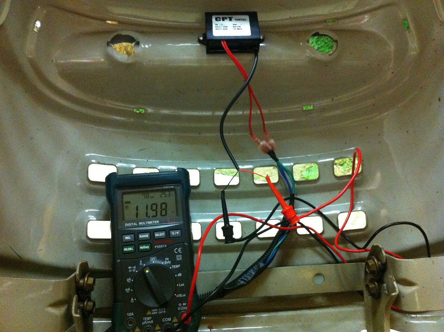
Well I've been making pretty good progress on this project for the past few weeks now. I do plan on doing a "build" thread once I'm finished but wanted to share some info and a few photos. First of all that AC-DC 12v regulator from Ebay works great (remember, the headlight wiring puts out 18v AC)! I get a steady 11.98v DC with no load no matter the throttle position (voltage does not rise/fall with the throttle).
Here's a pic of my homemade heatsink modules mounted (front emitter view):
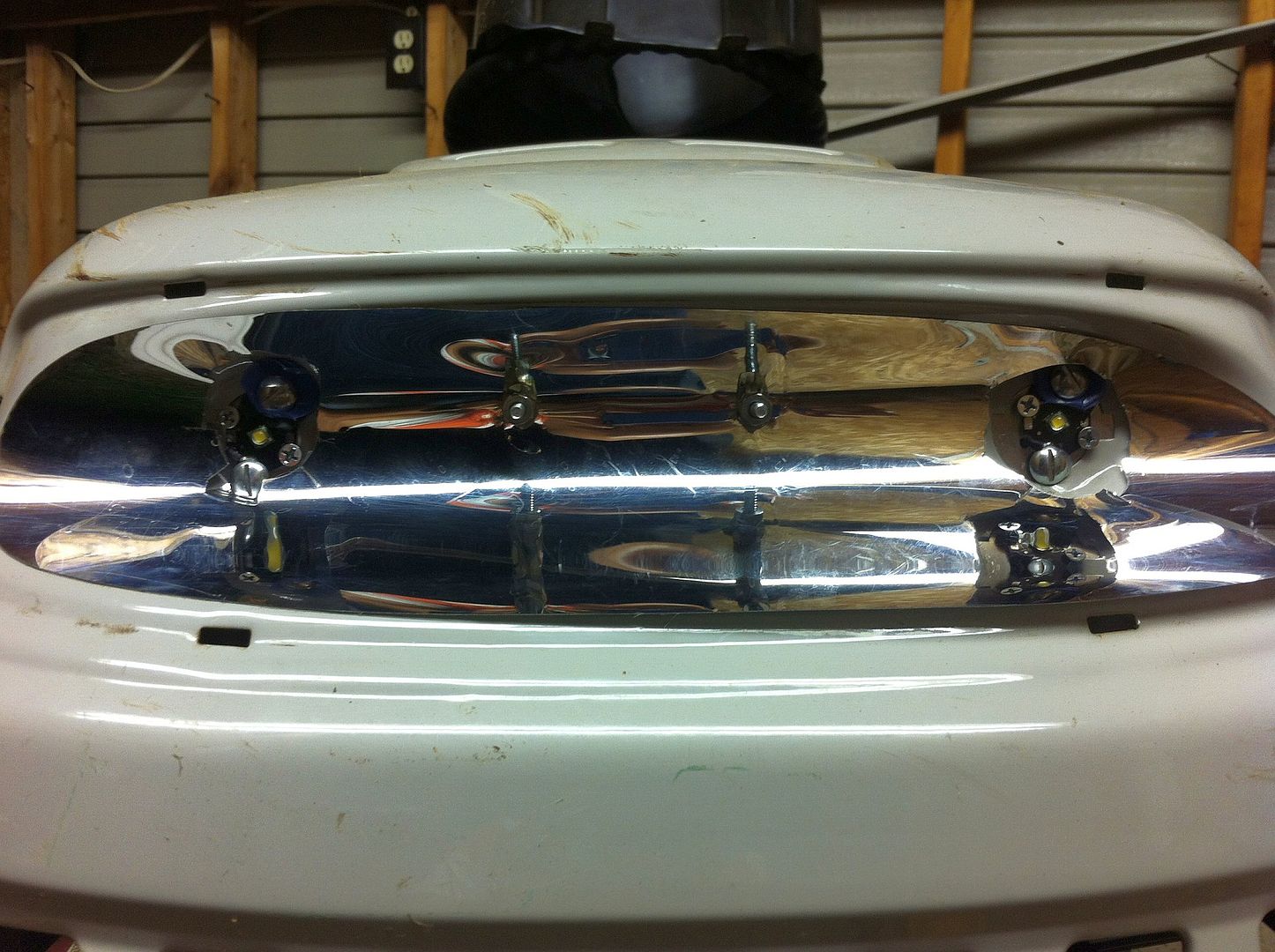
In the above photo you can see where I completely goofed up my measurements for the mounting screws (large head screws) placing them way closer to the emitter star than I intended. It works, but I had a heck of a time not shorting out the positive wire to ground (notice the blue plastic "washers" - they are cut from a coffee can lid). "Test for shorts first before applying power" is my new saying!
Rear View:
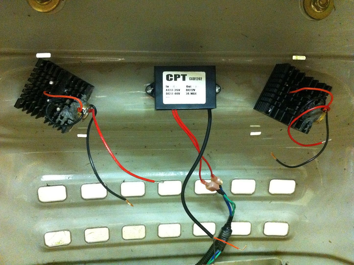
You can see in the above photo how I tapped right into the existing headlight wiring with terminals (and taped back the second headlight wiring).
Another goof up (just keepin' it real man, keepin' it real):
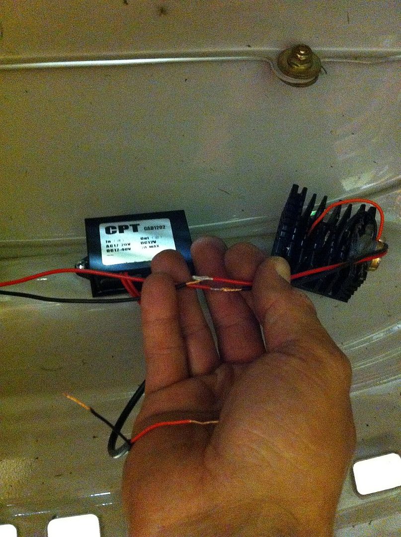
DOH! My wiring is too short! Double DOH!!! In the pic it looks like I am holding them in order to show positive going to negative, but that's just the way it turned out. The 3 positives go together and then 3 negatives go together (2 to driver, 1 from AC-DC Regulator).
Well I pulled the wires together and used alligator clips to keep them connected while I fired the mower up (lights don't operate unless it's running). And guess what . . . they work!!! The optics aren't mounted yet so it's full flood "candle mode". The output wasn't bright at all, but I'm figuring it's an optical illusion do to no optics in place. The front end of the mower (under the hood where the regulator / drivers are mounted) gets really hot due to the exhaust being on the front lower side of the engine; hope my work holds up to this heat.
You may have noticed in another thread that comfychair has talked me into going with the LM2596 modules to drive the emitters, even going so far as to setup low beam and high beam output levels operated by a toggle switch. This is because in my testing of the single mode KD driver the output is rather disappointing - only about 1.36A to the emitter.
Getting closer!
-Garry