Wondering if this set up exists? I know I have seen momentary drivers, but not with use of a dial. I have seen lights with this set up, but not for building.
When you say “momentary”, do you mean the light only works when the switch is pressed/semi-pressed and stops when released? isn’t that part of the switch design rather than the driver? (for mechanical switches anyway).
for e-switches there are a lot more possibilities…
and for rotary switches - they would “snap back” when released?
sorry if I misunderstood the question.
What I mean is use with a dimmer or ramping switch.
All Crelant light use dimming side switch and momentary tail switch.
My short review of smaller model 7G3CS
Looking for a driver that supports a dimming knob. Wicked hunting lights use an intensity knob. Pretty much what I’m looking for. Check them out.

Now its more clearly to me, that is a great future, but I don’t have any idea about driver that will support that kind of dimming.
Sorry
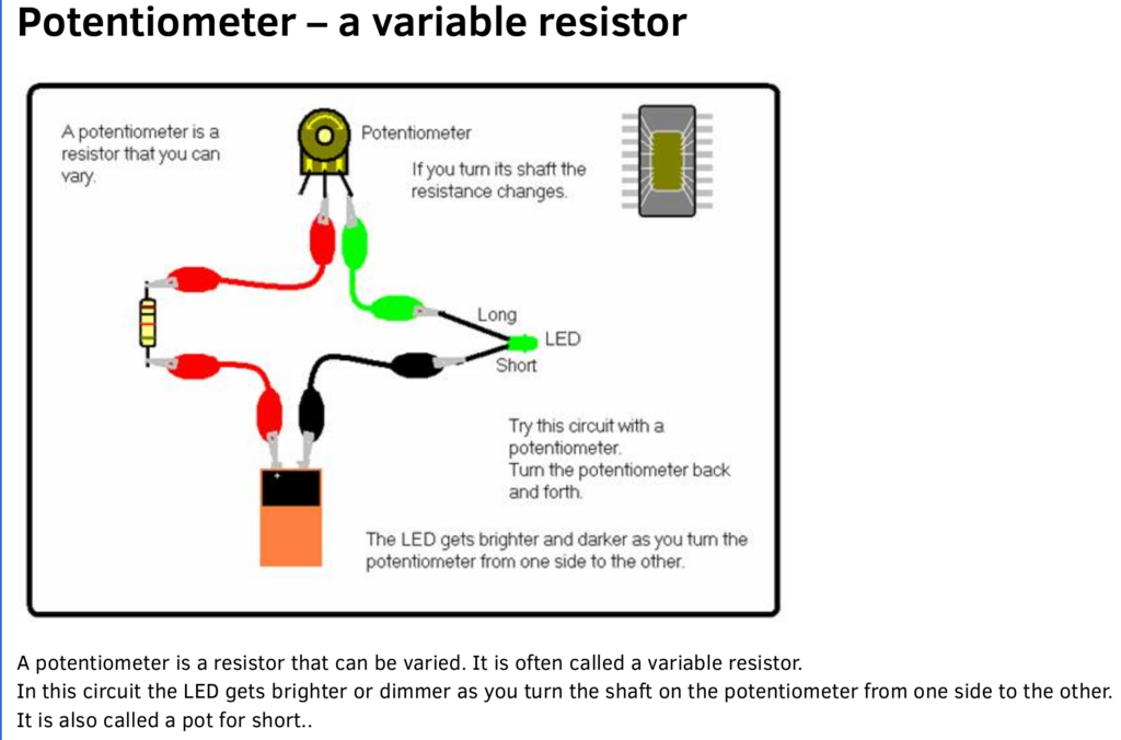
If there isn’t it would be very easy to design and build. Just a FET driver with output at 100% and using a POT resistor to limit output current. Turn the dial on the POT and the output changes.
The better way would be to hook up the pot to an adcinput of the controller…more efficient and the pot doesn’t need to be very beefy.
There was a similiar threads only some weeks ago…
Hmm, not exactly sure what you guys are talking about. Have to do some reseach I suppose.
Some have indents for fixed modes,but others are infinitely variable.Visually linear output ramping would be best.One problem,they are only available as complete torches,not just drivers.
For a 3v LED and a single li-ion cell this driver would be easy to develop in this community. If you need I can design the driver as long as a firmware person tells me what they want on each pin.
Would a single mode nanjg 101-AK-A1 driver work? Now this may be a dumb question, but if turned down, would it affect the voltage? I’d so, it would trigger the low voltage protection.
Sub
So I found this. Is this basically what I need to do?
I’m very basic terms yes. If we to use an attiny as well we can add reverse polarity protection and low voltage protection
Im sorry, im confused what needs to be done to the driver to make this work. Can you explain? Would appreciate it.
The circuit shown above is the simplest form of a variable intensity light. The important part of this circuit is that all the current flows through the light as well as the potentiometer. Which means that it needs to be beefy enough to handle the maximum current you want to drive your light (the A6 can get to 5A and more with bypasses and other massaging).
The other method is to use two ‘separate’ circuits. One low current circuit to adjust the amount of current that the LED gets. The pot would adjust the input voltage to a pin on an atTiny25 (or 18 or whatever), which would then ramp up or down the current to the LED.
The reverse polarity is not done by the ATTINY. It is done by a diode. A “basic circuit” like the one depicted earlier doesn’t need reverse polarity protection. The LED itself is a diode - Light Emitting Diode. Reverse the polarity, the LED just wont light but no harm is done unless voltage is outside the envelop of the LED. Simple stuff like the VR (potentiometer) has no polarity.
On the other hand, when more complex electronics, some would choke, smoke, die when polarity is reversed. Having an ATTINY doesn’t give you reverse polarity protection, it requires reverse polarity protection. With the NANJG 105c, the power to the MCU is routed via a diode that blocks reverse current.
I am more familiar with the NANJG 105c. I think the NANJG101 uses the same method. Understanding this would allow you to understand how drivers work.
There are two main parts. The power part of the circuit, and the control part of the circuit.
The power part of the circuit is your main water pipe, to use that as analogy. How much water flows out of your water main depends on how much the water pressure is, etc. etc. and the faucet setting. The control part is the faucet control.
The MCU in the NANJG doesn’t really turn the faucet more wide open (brighter) or less wide open (dimmer). This is a single level faucet - on or off. So, if you want half the water (half brightness), what it does is it turns off the water second half of every second. So, imagine if you divide the second in to 255 time-slices, you can have it turn on for 128 time-slices (128/255) and off the remaining 127 time-slices, you have just a bit over half. Or, you can turn it on 254 time slices and you are almost almost at full. The cycle is much quicker than a second. Read on.
Now, I said turning it on top half of the second and off the second half of the second. That will indeed give you half the water. But with LED, 1/2 the current doesn’t mean 1/2 the brightness. It is like the gas-pedal of the car. Pressing it half way down doesn’t really mean 1/2 top speed. You can consider it to be around 1/2 but not exact. Regardless, you do have 256 levels of control when you include zero (OFF) as a level.
For a flashlight driver…
The faucet typically is a FET (Field Effect Transistor), a MOSFET (Metal Oxide Semiconductor FET). NANJG uses the AMC7135 which is a current regulator - ie. additional electronics to the MOSFET. The AMC7135 will allow UP-TO posted limit and no more, whereas, MOSFET/FET would allow more if you have more. So with the AMC7135, you know each AMC7135 will let “as much as you can give” through but only up to 350mA for each AMC7135. So there is no concern of rushing more current than the design permits.
The MCU (ATTINY13A in NANJG105c’s case) has something call PWM. Pulse-width-modulation. This is the 255 time-slices maker. It divides each PWM clock cycle into 255 time-slices and can control at what time-slice it changes from ON to OFF - ie: the width of the pulse. The longer it stays on, (ie: the wider the pulse), the brighter the LED. The PWM clock cycle depends on how the MCU is programmed. It is typically some fraction of the the MCU clock. For the NANJG105c, I think the stock software has PWM running at around 9KHz if I remember correctly. That would mean each cycle is 1/9000 seconds. Within each 1/9000 seconds, top n/255 ticks will be ON, and the remaining ticks for that cycle will be OFF. The MCU send this output to the AMC7135’s so each one “hears” the MCU and turn itself ON or OFF correspondingly.
The MCU runs the driver program which decides based on setting the proper pulse-width to the AMC7135. And with this pulse-width “width changing” - ie: modulation, it controls the brightness of the LED. Imagine, with some LED’s it has 4 colors on the same die: red, green, blue, and white. With a more advanced MCU like the ATTINY85, you can have four different PWM each controlling the level of one primary color. So you can even mix it to make any color you want.
I have two ModeFiles for my NANJG 105c driver program. One is {10,20,90,255}. So, the first one turns ON 10/255 of each clock cycle, and off the rest of the cycle - very dim. The second 20/255 ON, then 90/255 ON. The last one is 255 of 255 ON, so that one is full power. I have four brightness levels. Each time the button is clicked, I advance to the next in the list.
The MCU get its power via a diode. That is a one-way valve. So that is the reverse polarity protection.
The driver program can get fancy. For example, the MCU also has the ability to read voltage. In fact, the NANJG stock software will read the voltage and begin blinking the light if it is below 3V. For me, I did something different. I program the “fifth” level to blink out the voltage. Blink Hi 3 times and Low 4 times means the battery is at 3.4V. (Actually, it is hidden that shows up on the 14th click, and the 15th click is the menu - it allows me to change to a different mode-File with 6 levels, or turn on/off certain features. I limit full-power to just 90 seconds because my cheapie lights doesn’t have enough heat-dissipation and on max-brightness, it would get too hot for its own good.) So, the MCU is the brain of the little flashie, and I control what is in the brain, as well as controlling how this brain makes decisions.
Merry Christmas, and I hope this explanation helps your understanding.
Rick
Finally had time to read all that. That was a lot to take in, but I somewhat get what your saying. Going to have to experiment with it, and see what works. In the process of making a testing station so I can try this outside of the host.
So I posted this link to video about Wicked lights earlier on. Then I found an intensity upgrade kit for their lights that don’t currently have one. Ok, now all I see is a pill, containing a red emitter, and some sort of driver I’m guessing. The kit also contains the tail cap that has the intensity switch, potentiometer, in it. Now all the tail cap switch does is complete the negative circuit, so how could you have the potentiometer in the back, and have it work? Wicked Lights W402zf to W403ic Red LED Upgrade Kit W/ Intensity Control Tailcap for sale online | eBay