im in the middle of soldering the components on this MTN 17 DD board. I'm down to the last two capacitors, and I don't know which one is which. They both look the same, with no markings at all. One comes in a clear sleeve, and the other comes in a black sleeve. They are both brownish and the same size. Can anyone help me out.
Assuming you have a multi-meter, but no capacitance meter:
You could try to charge both up to a small voltage (e.g. using the diode test on the multi-meter), then measure voltage to see which one discharges fastest through the ~10 Mohm input impedance of the multi-meter. 10 uF should take a while.
That’s way beyond me. I can hardly see and every time I touch one of these with a tweezers there’s a good chance it will fly into oblivion. Richard supplies these parts for DIY, there should have been some kind of indicator, even a colored marker on the sleeve.
I’m scrunching my eyes with a loop to tell if one is larger, but my eyes start playing tricks.
Stick it down on a table with blu-tac or similar, preferably under a magnifying work lamp.
Then, using both hands, touch the capacitor terminals with the meter probes. Probes with decent tips will make this much easier.
Unless the 1 uF has a much higher voltage rating than the 10 uF, the 1 uF will be thinner (same footprint, but lower profile) than the 10 uF.
Okay. One seems to be a tiny bit taller than the other. I’ll assume it’s the 10uF. It was hard to tell if it was my imagination.
Thanks DEL. I’m going to take a chance and go with this assumption.
Thanks is my first DIY driver, so it’s been slow going. The next one should go easier.
I’ll let you know if I can get the darn thing to work. I think my soldering has been pretty good though.
You’re welcome. I think I made similar comments about add’l instructions about the caps somewhere and I think someone answered there, but I can’t find it so far.
Okay. I tested it and got nothing. Maybe a faint almost imperceptible glow for a second. Ain’t that a pisser. I wonder what went wrong. Could be anything.
Does it matter which way the MCU goes on? It’s looks identical on both sides.
I could test the board for connectivity, but I’m not sure where everything is supposed to lead to.
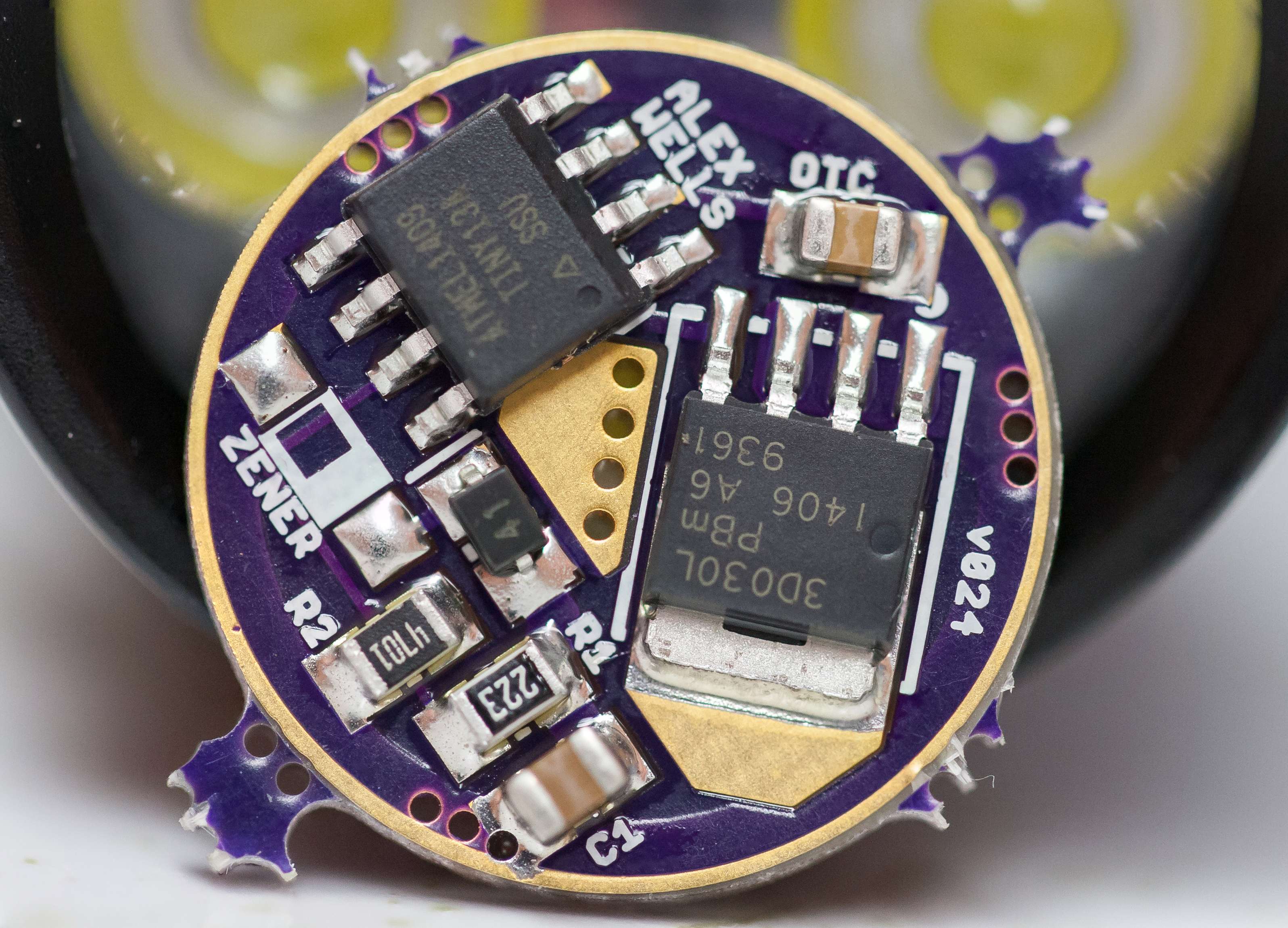
Yikes, most definitely yes - the MCU position matters. Again, it may be hard to see, but there's a circle or triangle on the MCU to mark pin #1, usually on the top, sometimes on the side. If you look under a glass at it, move it around to catch the right angle.
On the board pic above, you see the white asterisk marker just above the center LED+ pad? That marks MCU pin #1 position.
Also, you really need to buzz out all connections - on the whole board after assembly/reflow, but also off every MCU pin. Make sure all solder joints are truly good, and check for any bridges - you need to do close eye inspection - you really need to get a good visual setup - very important: magnification and light. I can do it with these ol eyes, and I work with a tech who is bout 70 who can see this stuff better than me, but it's all about the tools.
It does matter, and there should at least be a recessed round dot on the MCU, apart from the lettering, that dot should be on the side where the OTC is
Okay. Thanks for that guys. It seems I have the MCU on backwards. I can reflow the MCU, but do you think I probably damaged it. I’m installing the MCU on my second board now.
I wish there was a thread with detailed instructions for building these things.
Not sure if it survives or not, others may know better. Also the diode is important which direction it's installed. I think the FET is straight forward.
The diode protects the MCU from exactly that - reversal of gnd and Vcc, and since gnd is pin#4 and Vcc is pin #8, they would flip positions if the MCU is upside down.
Man! You guys are lifesavers.
I built a second board and it works perfectly. The first board should have worked perfectly too except there was no info about the MCU placement.
I reflowed the MCU on the first board, and it’s working fine. I was afraid testing it with the MCU backwards might have blown something.
Once you pointed it out, even with my eyes, I can now spot that dot on the MCU from a mile away.
That is a lovely soldering job on that driver. Mine never come out that clean. I don't know if it's something I'm doing or the type of flux or solder I'm using.
Mine come out look'n pretty much the same. Best way is to be conservative with the solder paste, pre-heat the board before doing the reflow. I use a hot air gun that has low air-flow, even spread.
It's not hand soldered, Dale does reflow as well, I believe hot air.

 djozz dug up that great pic. I've posted some in the past as well, but tough to find them, probably buried in some of wight's threads.