Here one of my homemade LED flashlight. I never used any special tools for it.
No lathe machine, no bench drills.
it doesn’t look nice. but I like to share my work with yours.
This torch powered by Samsung 18650 2600mAH salvaged from dead laptop battery pack.
It still show 2100mAH. so im lucky. I got this laptop battery pack for 8$ and had 6 batteries. 4 were ok. 2 dead.
other parts:
LED: Nichia NVSW119A mounted on 16mm star
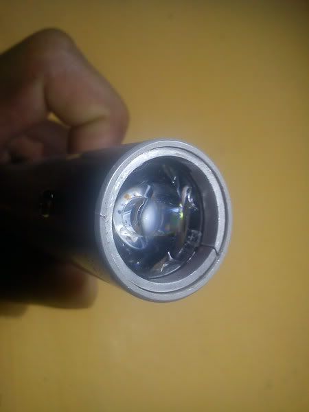
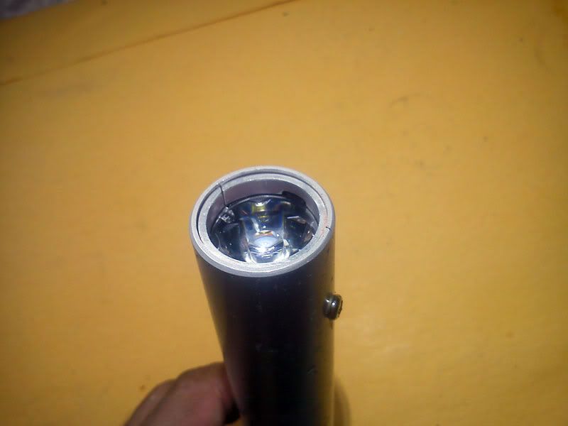
Optic: Carlco plain tight 20mm
Driver: 3.3V LDO regulator KA78R33 & series resistor
Body : Aluminum pipe from old grass cutting machine handle
Heat sink : Salvaged from UPS
I missed some photos that contain flashlight making prograss. anyway here photos I took.
Optic:
Aluminum blocks for mount Star MCPCB. I cut those blocks from solid piece of large heat sink. by hand and steel cutting saw. then grind excess by hand tools
Thread hole for mount screw. drill hole and then cut thread using screw and oil.
Completed!
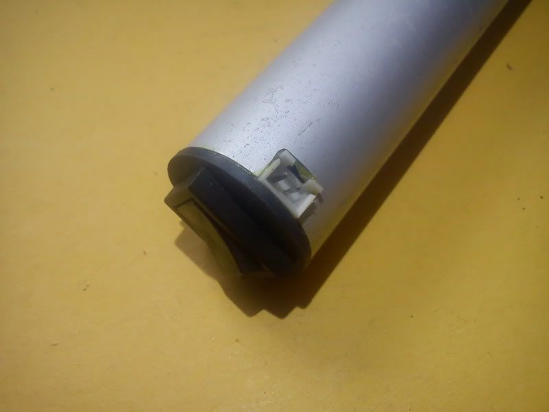
Charging port and on/off switch
Optic mounted using aluminum ring cut from same pipe
The setup is CV charging, but with current limit. 1.5A will be the max charging current even when the voltage difference is high. Once the difference of voltage between charger 4.2V and cell drops, the current drops as well depending on the total resistance.
1.5A is a bit high though for cell longevity IMO. And the circuit will try to charge your 0.5V dead li-ion too if you let it, so be careful with that! :)
Anyway, Pavithra, I have to congratulate you on your ability to use ordinary items to build this light. Nice job! One thing I'd like to know, everyone else normally use current regulator, but you use voltage regulator, any reason? And how's the result?
Reason for using Voltage regulator:
it has very low dropout voltage. so I got nearly full light output battery dishcharging
I have few regulators in my hand and didn’t have AMC7135 like regulators. I will use AMC7135 for next lights.
I modified output voltage & charge current monitor values.
To limit 500mA charging current: R1=1.2 ohm (1W)
To set output to 4.2V : R2 = 1 K.ohm & adjust R4 to 4.2V or combined R=1110 .ohm
To turn off LED after charging current drop below 50mA : set R6 to 10 .ohm
I suspected that’s the one from your description. I tried building V3 of that circuit, but I made a mistake somewhere, my circuit behaves very strangely.
Unfortunately I have no useful way to debug it, other than starting from scratch. Well, you might have some knowledge of how that circuit internally works, if you have any time/will to help me debug it, that might help me save it.
In any case, your info about V2 might make me go revisit this circuit. I started building it before I got my first 18650 flashlight and charger, with only some salvaged old laptop 18650s to test it with. Unfortunately, no positive results so far.