can the zener mod be combined with the reverse polarity protection? My idea is to add the standard diode in series before the 200 Ohm resistor.
The original Nanjg 105c zener mod simply did not have space for all, so it is just resistor instead of the stock diode (and the zener on top of the capacitor). But with all these Oshpark possibilities and larger driver boards…
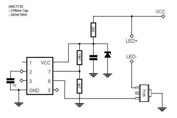
This is the usual zener mod (ignore the off time 1y cap).
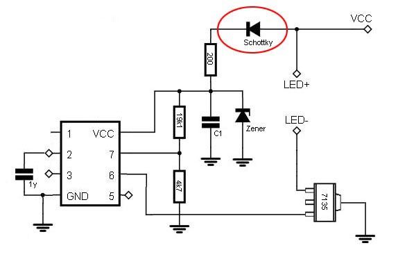
And this is what I have in mind. In my imagination the 1N4148 EDIT: schottky-diode will just work as in a standard Nanjg, e.g. blocking when reverse voltage is applied, and the zener mod will protect the MCU from the higher voltage. Will that work?
Thanks for helping me out on this one.
EDIT: corrections to the naming of parts in the circuit
Note that the voltage divider somewhat lost it's function there; if you make a new board, connect the upper voltage divider resistor to right after the diode, use suitable values (like 100k/10k) and a suitable threshold in the firmware.
There is no need for a series diode for reverse polarity protection. The zener diode/current limiting resistor does that for you. If you connect the supply backwards the processor will see –0.6V.
Thanks DrJones and texaspyro for the explanation. I understand the Zener protects the MCU as a bypass. This seems to come at a cost of a drain through the 200R and the Zener, that might empty the battery.
I also hope to have understood correctly that if I felt… compelled to install a true reverse polarity protection I’d simply add this tiny little Schottky-diode and we’re done? Zener Mod working - and an adaption to the resistors (and the firmware) even gets the low voltage protection back to work. So the all-in-one solution would be this?
Yes it would but note the excess battery drain you’re talking about is only on momentary switch drivers, since the batt is always hooked up the Zener is always burning off voltage draining the cell (while only a couple mA this is magnitudes over what an “acceptable” standby draw is from only the MCU). In a tail clicky / power cycle controlled light this isn’t a problem since power is physically disconnected when off.
I know it’s more of a theoretical problem. Worst case should be 8.4V and 200Ohm (zener ignored), makes 42mA.
Well, the LED won’t light up, you might not see it and leave the tail clicky on… drain 2 batteries unnoticed… get some fireworks later…
0:)
Nah, my thoughts are more like: It works, it has a slight advantage, I got enough space on the PCB and I only need a component worth 5ct. That’s ok with me.
I just wanted to be sure not to render the circuit unusable. So thanks again.