So for the fun of it, I wanted to see if I could get an S2+ with the metal style button to handle high amps. Around 15A.
Is it possible with the limited space in the tailcap?
I did my usual bypass on the spring, and when setting thermal protection, it cooked itself around the 20 second mark.
Any tips or tricks for getting this to work?
1 Thank
Try soldering the 20A switch to the 16mm board. Might be a pretty darn tight fit and I don’t know about the length. Might need to file the button and the pusher down.
1 Thank
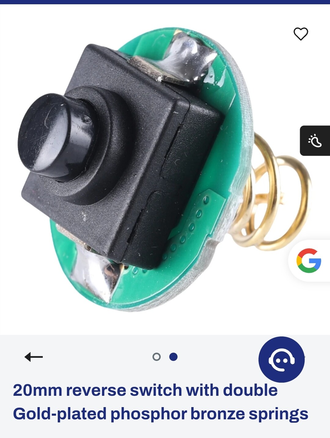

I have both of those switches. They are a little longer, and are 12x12ish mm square. The stock switch is 12x8mm rectangle, but I have an idea to make one fit. It’ll take some modifications to the actual button portion, but I think it may work.
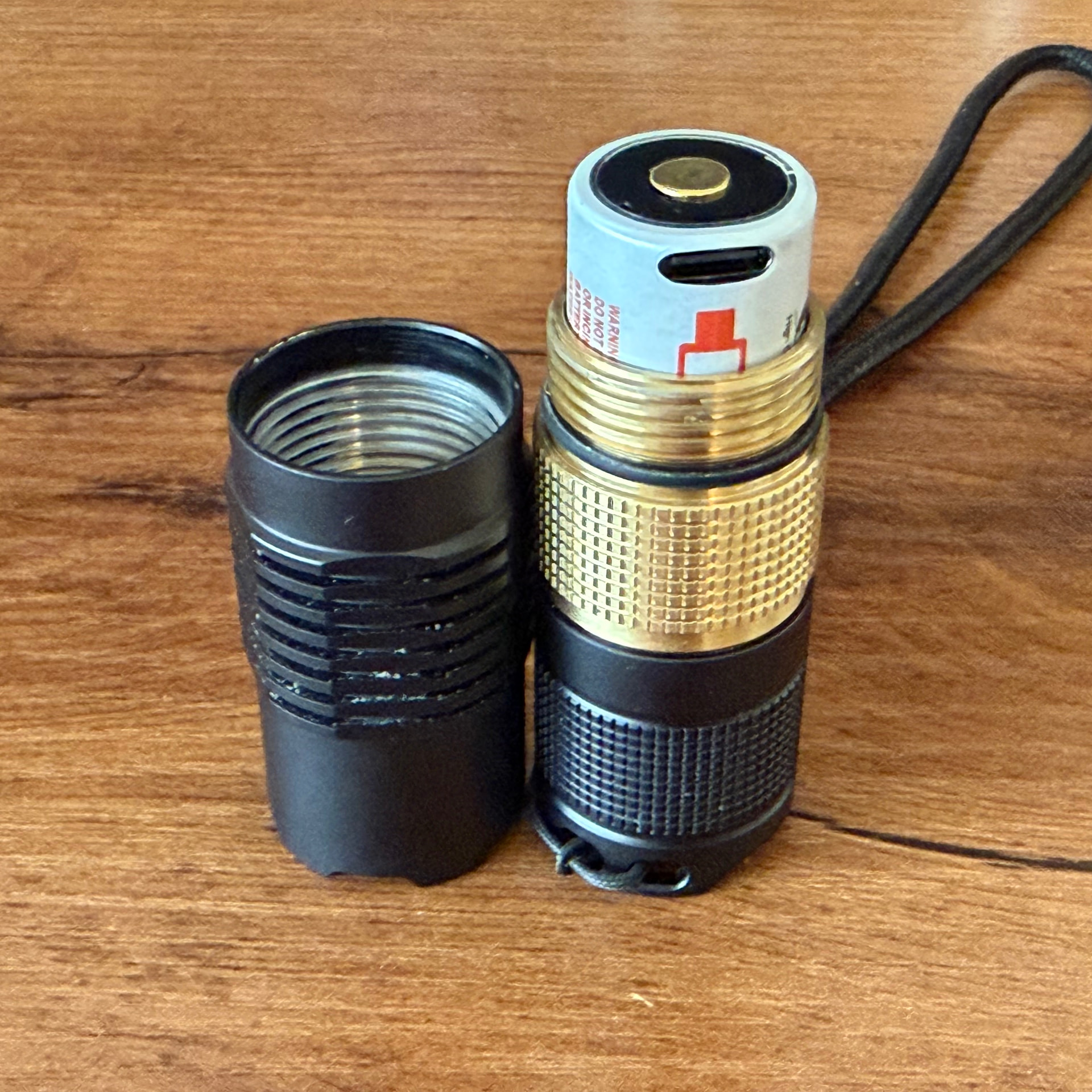
I unthreaded the metal button housing from the tailcap. My idea is to add a spacer under the metal button assembly before threading it back in, to give me an additional 1mm ish space I need for the extra length.
I’ll report back tomorrow on whether or not it works.
If that fails, my backup plan is to drill about 1.5mm into the underside of the metal button where it interfaces with the switch, to give clearance for the additional length the higher amp switch needs.
Keep your fingers crossed for me.
1 Thank
I think it’s possible, I fitted one on a T6 last week!
It was REALLY tight and I had play with different spacers/washers, but it’s working and I’m less concerned of meting it now ![]()
2 Thanks
Ok, cool.
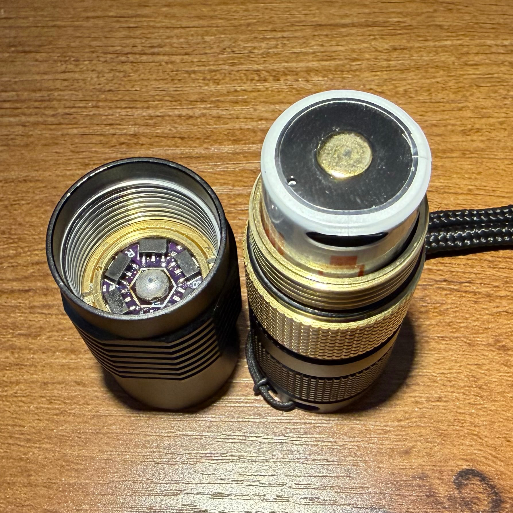
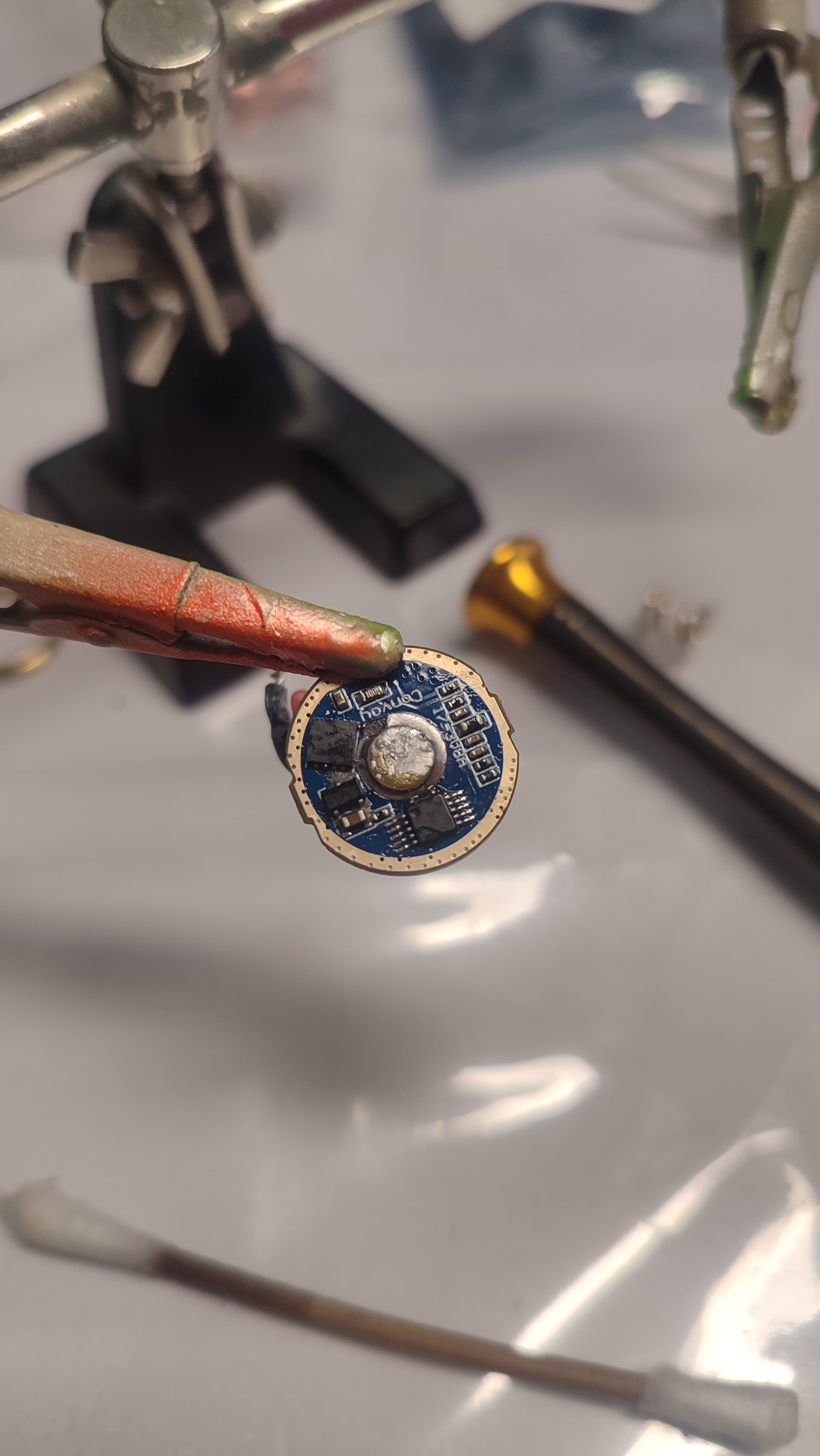
I soldered the 12x12mm switch to the 15.8mm board, and it’ll definitely work with spacers, or with a hole drilled into the underside of the button.
For proof of concept, I put it all together.
The light wouldn’t turn on.
I unscrewed the metal button assembly from the tailcap in increments, testing each 1/4 turn. About 1 full turn from seated, the light functions now. The only issue is with the assembly unscrewed far enough, I lose tailstand ability…but it works.
So I can add a 1.5ish mm spacer under the assembly, or drill a hole in the button.
For right now, I just used an oring for a spacer.
I’ll probably end up drilling a hole in the button for the needed clearance.
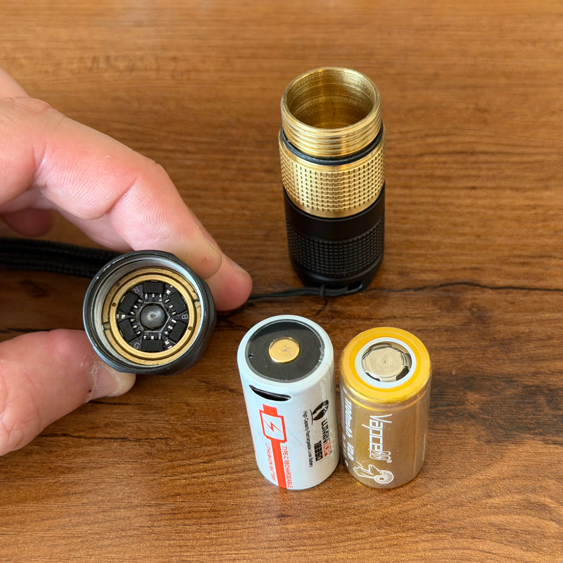
The build is a 17mm Texas Avenger Fet+6+1 with an XHP50.3 5000k.
With a keeppower 1200mAh 18350 it is pulling around 10 amps.
With a Samsung 30Q 18650 it’s pulling around 14 amps.
In the pic you can see the button assembly is unscrewed quite a bit.
If I drill the button, I’ll use the aluminum black button.
If you file down the metal pusher you might win enough length for the switch to function properly and still have the tail stand options. 1 full turn is 0.75mm as that’s the thread pitch and the pusher has enough meat to be removed. If not, then file down the top of the switch some too. I’m just trying thin on my T3 but the difference in length is about 2mm.
2 Thanks
Good idea. I have a few spare buttons, and they are cheap, so I don’t mind tinkering with them.
1 Thank
I need to get it all the way down to almost a sharp edge and kkep the lip for the rubber skirt to stay on
1 Thank
Yeah. That’s a close one.
Most of my tools are in my storage, so I may try drilling first, as I have a drill in hand.
Probably still won’t leave you with enough travel for the switch to lock/unlock as you’ll hit the outer edge of the switch.
1 Thank
Ahh yes. I’ll have to take some measurements of the switches travel.
Worst case scenario, I have to run to storage and grab my mini bench grinder.
1 Thank
So I ended up doing one last thing before breaking out the power tools.
I added a 1mm thin aluminum spacer between the switch and the factory spacer, and a slightly thicker oring under the thread in button assembly.
This allows me to screw the assembly all the way down.
The only downside is I probably can’t use button top batteries as I lost a little real-estate inside the battery tube, but that’s OK, as I have tons of flat tops.
I’m still gonna mess with the the button mods later, but for now it is good.
2 Thanks
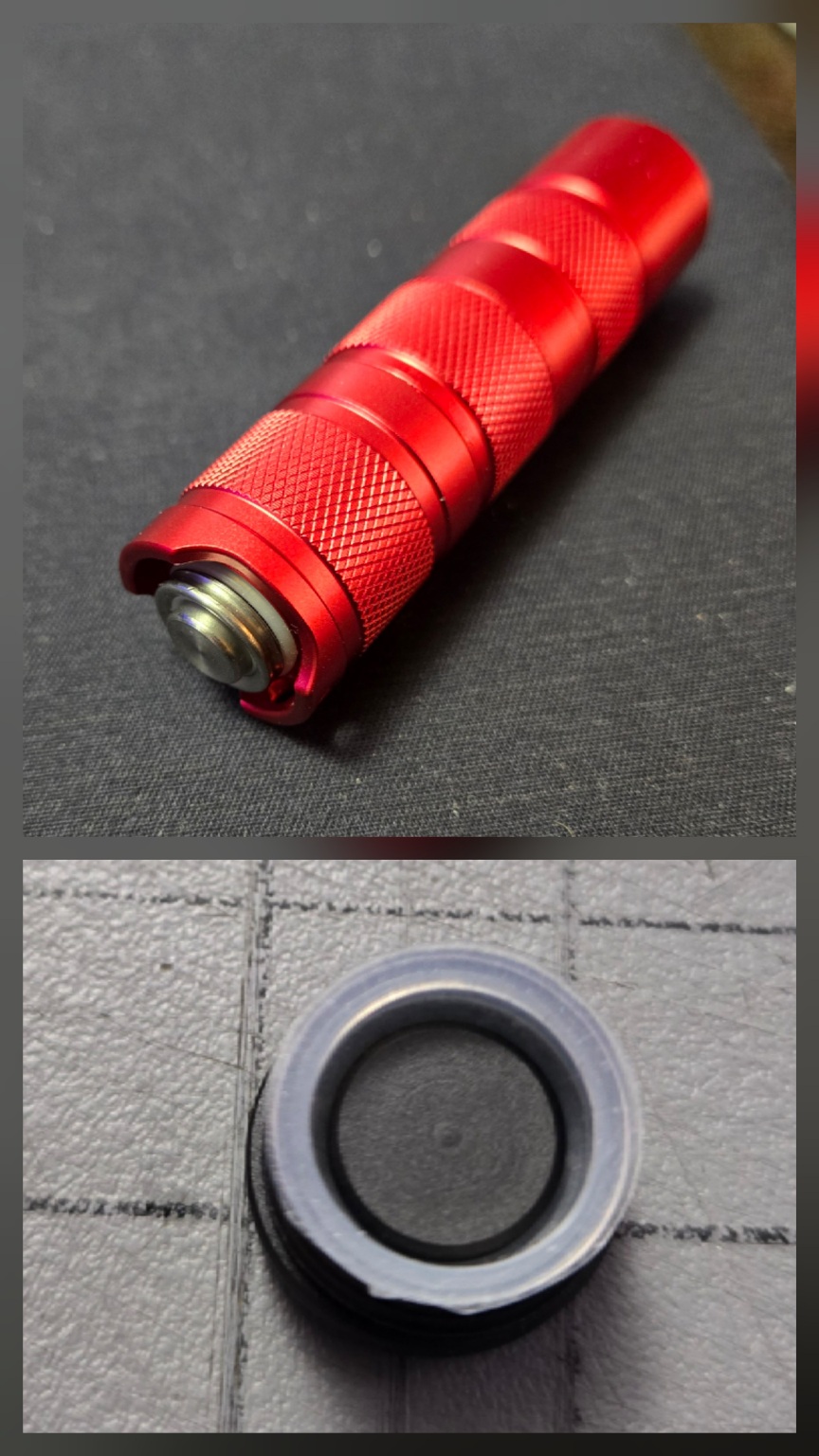
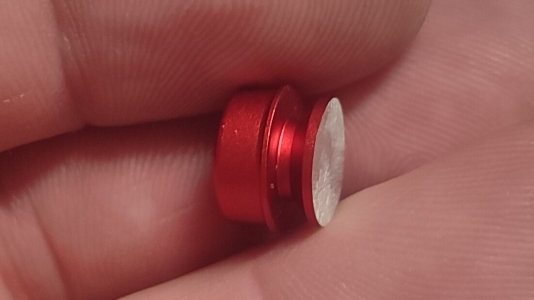
You could replace the driver spring with a brass button to recover some space if you really need to use the button top cells.
I just did that to fit this giant “18350” inside a short tube:
2 Thanks
Yeah, I’d thought about that, but actually prefer flat tops.
I had to do this as it was a T8 also in the T3
2 Thanks
You can just put a bigger solder blob!
The one I did today still works with flat tops
1 Thank
I just remembered I have some thin 2oz convoy tailcap pcbs arriving soon from oshpark. That’ll also gain me a little extra room as well!
FET tailswitch:
1 Thank