Hello, recently got this driver from FFL. While I was testing it with my bench supply it worked fine but then it just stopped working after I ramped up the brightness.
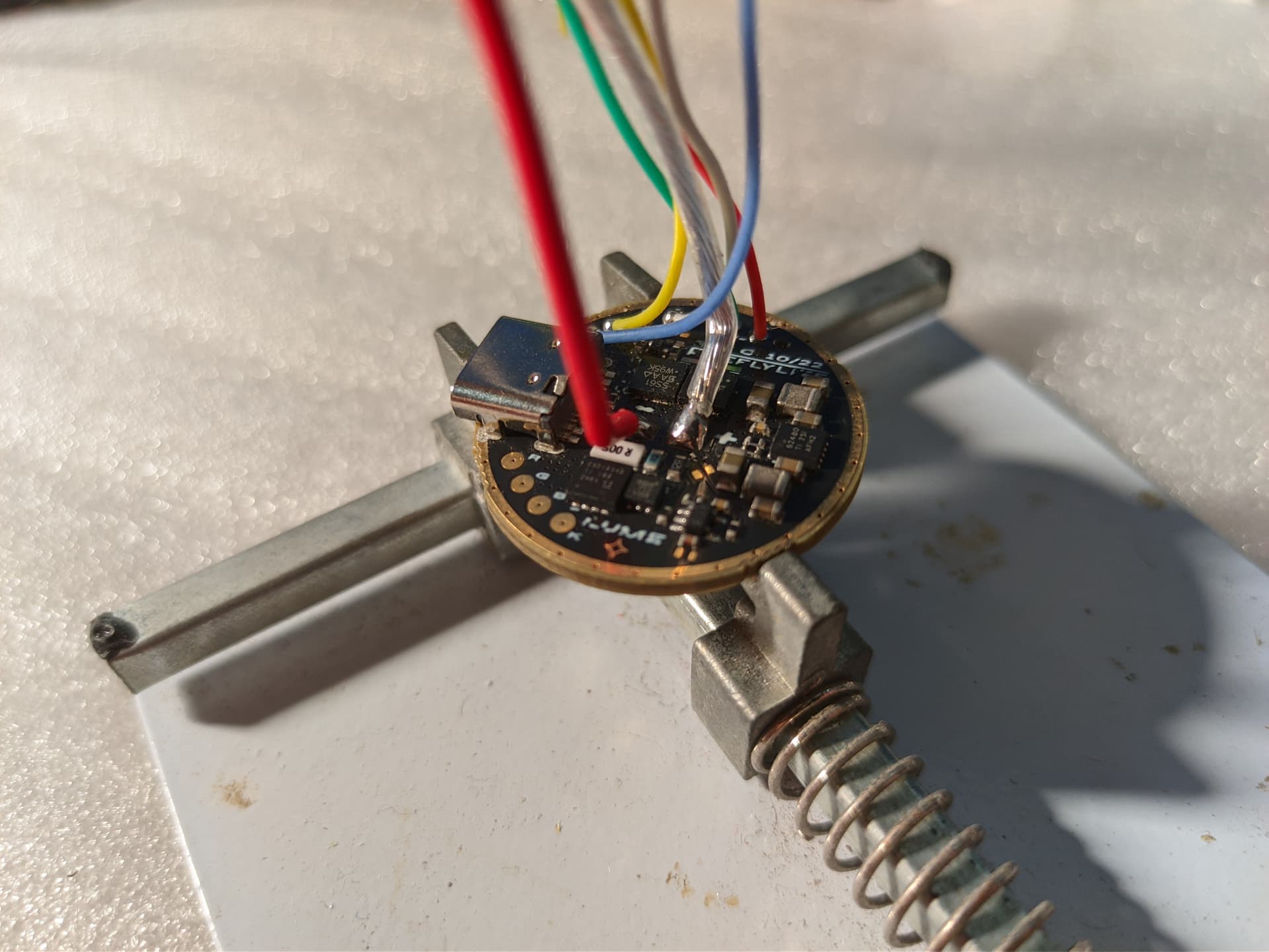
What I did was hooking it up to a test LED I have mounted on heatsink, using my bench supply I gave it 3.5V 500mA limit since I don’t want to fry it if I short anything, but I think this backfire on me. It does the LED blink after giving it power, I power it on and the LED light up normally, for some reason I decided to ramp the power up on the driver, the LED did briefly get brighter before it shut off cause the driver LVP kicked in since it draw higher than the limit I set on the bench supply.
The thing is, after cycling the power the driver won’t power the LED anymore, not even a flash when you give it power to the driver. Nothing smell burning and the voltage for the e-switch is there, the charging also still work. There is no short or anything when I power it, and doesn’t seems to draw any power aside the quiescent current for the driver.
The driver look physically fine.
How did it die when there is no overvoltage?
Did it somehow manage to wipe/corrupt the microcontroller?. Sadly I have no tool to reprogram it yet.
Kinda dumb of me testing this driver out, but still don’t make sense that low voltage killed it when there is LVP.
Any clues or help would be appreciated even tho there is not much that I can do with it. Just feel really sad to kill it
oh sorry, the vise was just there to take picture, the driver was left “floating” when I was testing it. But I don’t think it touch anything, the only thing that is touching the outside ring was my alligator clip for the negative
Buck/boost converters are usually really sensitive about input impedance, and a lab supply in konstant current mode is essentially a super high impedance power source as soon as the CC kicks in. Good possibility it fried because, not despite of the limit
Also, the (usually) long leads from supply to driver are not ideal as well, without adding some significant additional buffer capacitor close to the driver.
Nah, pretty sure the same would have happened with mostly any power supply in CC mode.
Usually buck/boost need quite a lot of input capacitance for low impedance power. On flashlights we often omit some of those and go under spec due to space constraints, and because the battery is a close by low impedance source.
Replacing the battery with a power supply with long-ish leads by itself can cause some problems, but the OCP kicking in is dangerous.
If you have access to a hot air station you can most likely just swap out the buck or boost controller. Should be quick and cheap
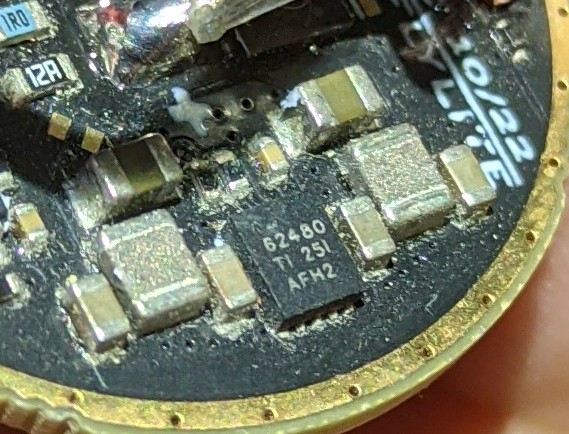
I do have hot air station. The driver uses the TI TPS62480. If I didn’t look up the part numbers on the IC I wouldn’t know that this was the buck controller, never seen inductors this small used for high power stuff before.
Mouser sell it but that shipping isn’t cheap to Indonesia.
Hopefully I can still somehow get it for cheap, would be fun thing to do, assuming the microcontroller didn’t die as well.
(And yes, the driver is that dirty when it received it)
If you have no schematics and don’t know how to detect defective part you have to learn how to do it . Now you just pocking with a stick. Get multimeter or better oscilloscope and search for signal.
You right, just got up and read the datasheet for the TPS62480. Don’t know why I didn’t check and test this in the first place.
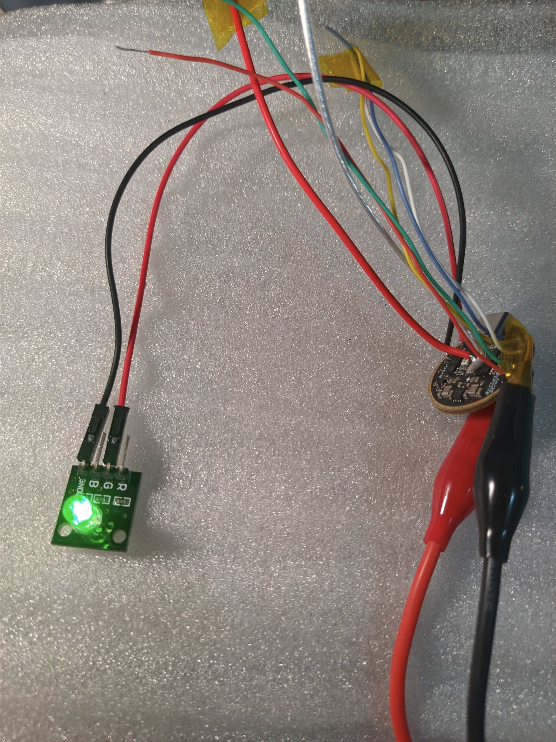
I injected voltage to its Enable pin while also powered the driver, and the driver actually output something. And to make sure it wasn’t the injected voltage that got outputted I change the supply voltage and it follow the voltage correctly in the output.
Now I just need to figure out which pin of the ATtiny1616 is connected to the Enable pin of buck controller, since it clearly not spitting the proper signal for it, but I don’t think I’m gonna gain much from this. I ordered a CH340, see if I can reflash it
Sorry I don’t have the best equipment to do it, and probably could just use the voltage measurement from the DSO. And sorry for shitty video quality and setup lol
Basically I use one of my multimeter on diode test mode to inject 4V into the Enable pin of the buck controller, then I supply the driver with 2.5V to 3V then goes 2.5V and under till the LVP kicked in, the scope show the voltage does follow the supply input so the buck controller is fine.
I think it’s unlikely that you’ve damaged the microcontroller, assuming that you can controller the aux LEDs with it. And if you have, reflashing it won’t help.
Secondly, be careful injecting voltages into stuff. In theory, that enable pin is connected to the microcontroller, so if it’s trying to drive it low, and you’re applying 4V you may well exceed the max sink current for either the pin or the device.
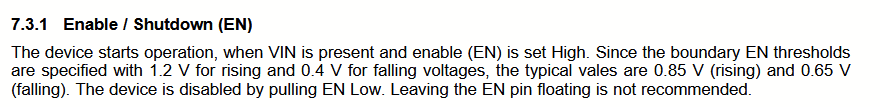
I’d recommend getting some fine tipped probes for your multimeter and then tracing where the enable line is supposed to go, and also checking other voltages on the circuit when the driver is turned on. I’d start by checking the enable pin (should be high when on) and the FB pin (should be 0.6V).
The regulator is supposed to output a fixed voltage, provided that the input voltage is above the nominal output voltage, which is set by the microcontroller, and the behaviour of the driver will be different with a load attached.
I’d also give the board a good clean. It’s hard to tell from the photos if it’s just dirt, or if some of the solder joints look a bit suspect.
Yes, the mcu get proper voltage for its Vdd
The enable pin of the buck seems to be connected to pin 11 of the microcontroller. “Pressing” the e-switch does nothing as the mcu is not outputting anything. I assume it suppose to output something, to enable the buck controller judging from its datasheet
It’s probably connected to three different resistors, so you should be able to test it even if you can’t access it directly, although no signal on the EN pin is a more obvious problem.
Yes, the en pin should go high when the light is supposed to be on. Is there continuity between the driver pin and the controller pin?
I think this file is the hw definitions for Anduril 2 for your driver. The enable pin is PB3 which is indeed Pin 11. It should also be connected to the power pin of the op-amp, which is the 5 leg chip near the “E” of “LUME”.
Yeah there is a continuity between both pin, tried measuring it directly from the mcu and there is no voltage at all.
I guess there is only two thing left to try, first I’ll try reflashing it to see if it does anything and if not then I’ll order a replacement Attiny1616.
I hooked up an LED to the output of the driver and feeding it proper power, then giving signal to the enable pin does make the buck side of it work.
Just to be clear, are you able to control the aux LEDs via the button? If so, then that suggests the firmware on the controller is fine, and either the output for the PB3 pin is damaged, or the firmware is refusing to switch the light on for some reason. A couple of things you could try:
Firmware reset (13H, or hold the button while connecting the power)
Check the voltage of pin 7 (PA6) for any signs of life. This should be a voltage between 0 and 2.5V that controls the brightness of the LED.