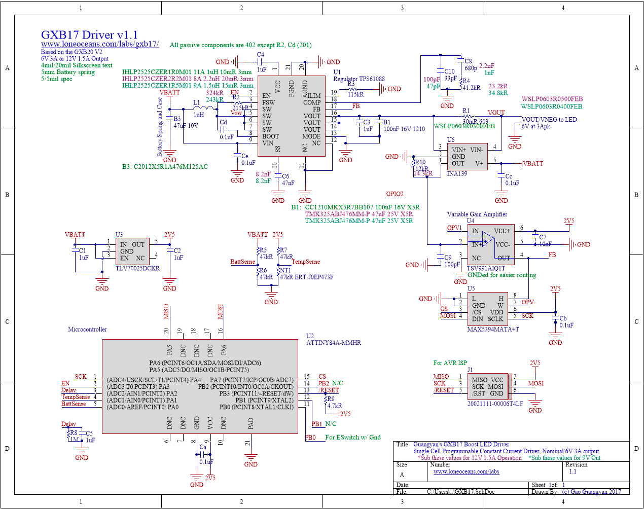
Hello everyone. I’m an electrical engineer from Spain who recently got into the flashlight world and decided to try and design my own LED driver. I wasn’t very happy with some of the fixed current driver designs out there and that’s why I went for a boost converter configuration: From a single LiIon cell input to 6V LED output (or two 3V LEDs in series).
As explained in the title, the design is divided in two parts: The boost converter itself (which is completely working. I’m able to get up to 96% efficiency from it) and the control loop. I wanted to control the converter to get constant current instead of constant voltage: In order to do this, I substituted the simple voltage divider going into the feedback pin of the boost converter for a current monitor + amplifier. This way, I can read the current at the output of the converter, and transform it into a reference voltage that I feed into the boost converter IC feedback pin.
Here’s a picture of both PCBs. The big one being the boost converter, which works fine when I use a simple voltage divider made of resistors. The small PCB is the current loop. The potentiometer controls the gain of the current loop, which allows me to vary the output current of the driver.
Here’s the boost converter schematic. It’s based around the boost converter IC with integrated switch TPS61088 from Texas Instruments. In the datasheet they state that the feedback pin should receive a voltage of 1.212V coming from a voltage divider between the output pins.
Here’s the current loop. I use an INA250 as current monitor (due to the super low, 0.002 Ohm integrated shunt resistor), a TLV8811 OP Amp to amplify the output of the current monitor, and finally a TPS71728 linear regulator to keep an stable voltage for both the current monitor and the amplifier.
As explained, the driver board, when used with a voltage divider to give the voltage reference to the feedback pin, works like a charm. I get a stable output with no noise, perfectly stable across the whole input voltage range. The input voltage is also noise free, both when using a battery or a laboratory bench power supply. The efficiency is also always above 90% from 0.001A to 4.5A.
But when I try to control the output current with my current loop PCB, that’s when the problem starts: For the same input and output voltages, and same power consumption, the output is constantly oscillating and I get tons of noise on the input voltage as well. The average output voltage and output current are more or less where they should be, but the efficiency drops to 60%, the feedback loop starts to oscillate… It’s just a mess. Here is an oscilloscope capture of the input voltage (yellow) and the output voltage (blue). Note how the input voltage gets a nasty oscillation when the output voltage rises every cycle. The circuit itself also starts making sound at the switching frequency (when controlled by voltage, the oscillation frequency is way over the human hearing limit, but when using the current control, there cycle happens at around 500~1000 Hz).
Here is another capture of the input voltage (yellow) and the feedback voltage produced by the control loop PCB, which is fed into the FB pin.
Is there an obvious mistake in my design? Why does the whole thing oscillate like that instead of giving an stable output like when controlled by voltage?
It would be very appreciated if you could post your thoughts or questions, so I can solve the problem and iterato on the design to make it even more efficient.
Thank you in advance for the help!


