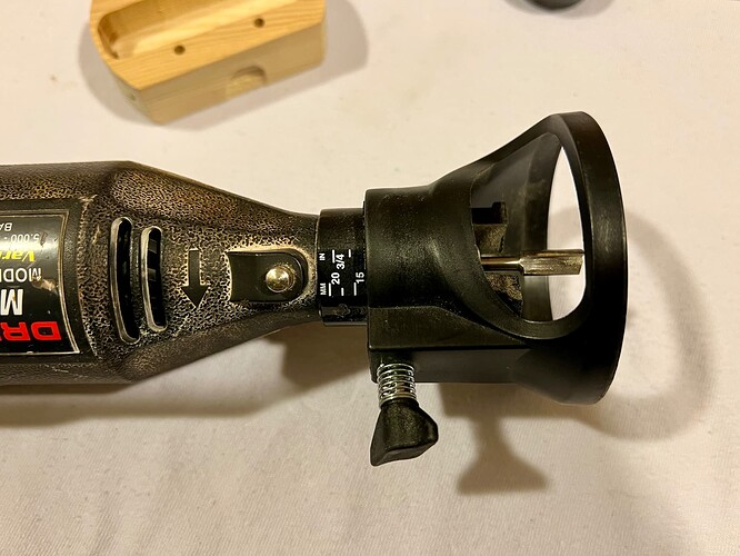
Does the Dremel have a depth stop? I’m going to try using a bit like that for a project
Yes, the depth is adjustable. I’ve also used it on drywall to make holes for outlets. It’s a nice Dremel attachment.
Ah… that smooth greens … Love it
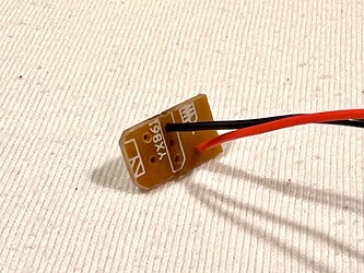
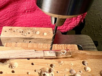
I used 26 AWG Teflon wire for the ancillary light. I installed them thru the back of the circuit board and then drilled another hole in the plastic hose to route the wires.
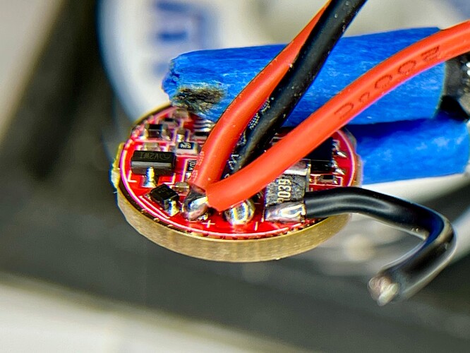
For the main LED I used 22 AWG silicone wire. I used a DMM to determine where I could connect the positive and negative from the battery to the component side of the driver. The positive can be soldered to the positive LED wire and the negative can be soldered to the sense resistor.
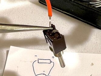
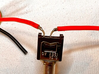
Then I attached the positive wires to the main switch. I bent the switch leads to go into the direction needed for the wires. My dad taught me a technique to protect sensitive components from the high heat of soldering, which is to attach a tweezers in-between the component and the soldering so the heat is absorbed into the tweezers rather than going into the component. The switch may not be that sensitive, but wanted to be safe just in case.
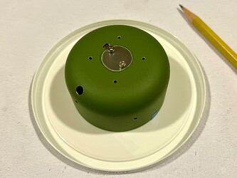
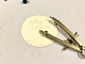
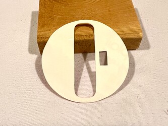
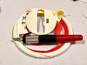
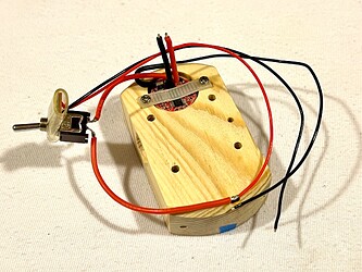
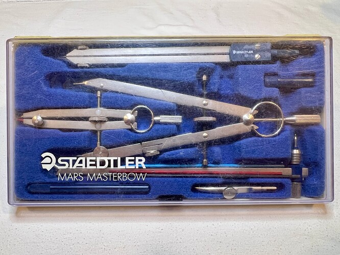
For the inside, I’ve thought about making a cover for the wooden body to make it look more “professional”. So I tried making one from a plastic container cover. First I traced it from the canister and then needed to make it smaller using a caliper that I haven’t used since college.
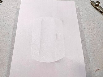
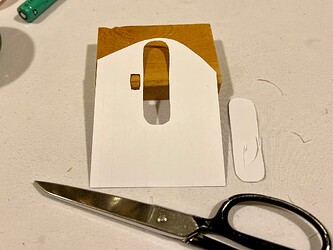
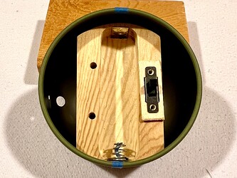
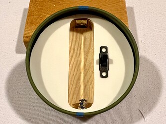
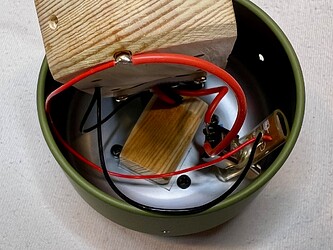
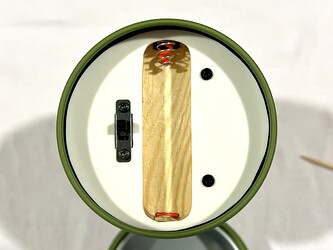
For the battery and switch cavities, I placed some paper over the body and pressed down to make outlines. Then cut them out using a scissors and put it onto the plastic cover to draw where I needed to use a precision knife to cut them out. The first cover I made turned out ok, but the second turned out much better.
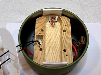
Here’s the inside without and with the cover, so obviously (to me) it was worth the effort.
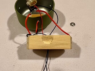
Next was soldering the wires to the battery connectors. There wasn’t a lot of room to attach the wires, so I taped them into position. Then added some soldering flux and quickly pressed a blob of 700F solder onto the wires.
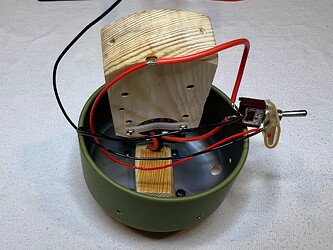
With the wires now soldered, time to start assembling the light. First was to screw the bulb base into place, then secure the driver, and push the LED wires thru the hole of the canister. Then screw the switch into place. I had to Dremel the switch body cavity a little bigger to accommodate the wires.
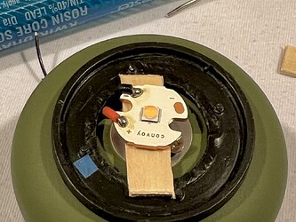
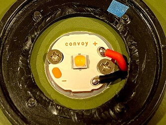
Then I soldered the LED wires to the MCPCB, added some thermal compound, and screwed it into place.
Then I positioned the wood body into place and secured it with the 4 screws. I love it when everything starts to come together!!! ![]()
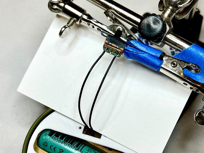
For the ancillary light switch, I used extra long wires in order to accommodate the inside cover I made. So the last part of the inside assembly was to solder the wires to the switch and then screw the cover into place.
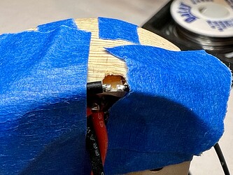
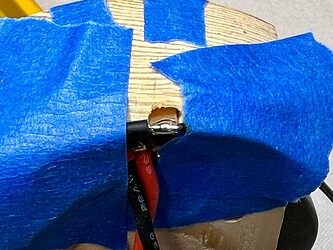
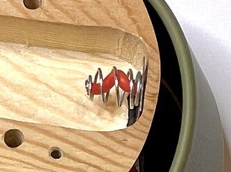
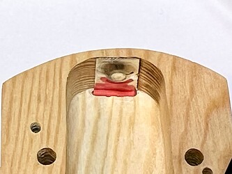
BUT WAIT!!! I noticed that the spring bypass wire became disconnected. ![]() So I had to take the light apart enough to remove the spring and replace the wire. This time I went with a 22 AWG wire and twisted it in the spring to help with the springiness. Before the wimpy spring became shorter and a non-protected 14500 was not long enough. So I guess this setback wasn’t necessarily a bad thing. I also used the sleeve of some silicone wire and squeezed it next to the battery contacts to keep them in place.
So I had to take the light apart enough to remove the spring and replace the wire. This time I went with a 22 AWG wire and twisted it in the spring to help with the springiness. Before the wimpy spring became shorter and a non-protected 14500 was not long enough. So I guess this setback wasn’t necessarily a bad thing. I also used the sleeve of some silicone wire and squeezed it next to the battery contacts to keep them in place.
Then re-screwed the body back into place and finally screwed in the inside cover.
Next up will be the final assembly.
Me too. I still have, and use the Staedtler drawing instruments from university 60 years ago.
You’re doing great with this.
Two things got me going on this project. First was the canister that we got from our neighbor when they came back from a trip to Japan. They gave us a bag of goodies including the canister which had some cookies in it. I liked the canister and held onto it.
The other was the toggle switch. It was in with a bunch of electronic parts that I got from my dad. I like the look and feel of it and wanted to use it for something. AND, the switch was made in Japan!
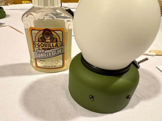
For the final stage of assembly, I needed to secure the bulb to the base. I thought about trying to screw it into place, but there just wasn’t enough space. So I reluctantly had to glue it. I put some Gorilla Glue around the permitter of the base and set the bulb in place.
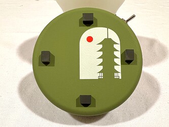
And lastly I attached 4 rubber feet to the “bottom” lid.
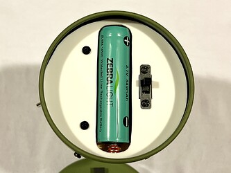
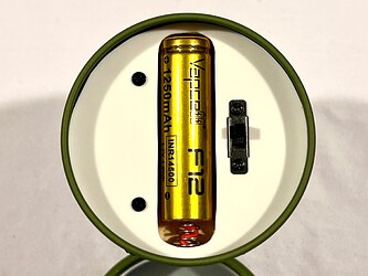
Here’s how a protected 14500 battery fits vs a shorter non-protected flat top battery.
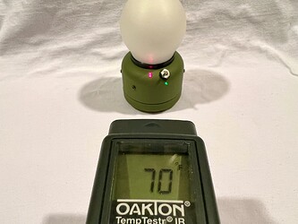
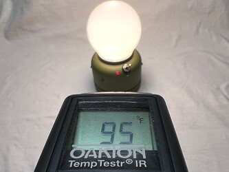
I then tested to see how hot it got when on high. After about 5 minutes, the light went from 70F to 95F. So it got pretty warm, but definitely not hot.
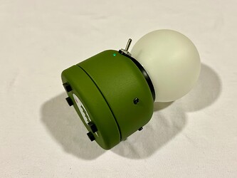
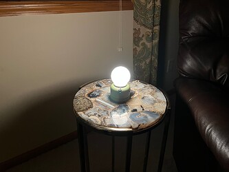
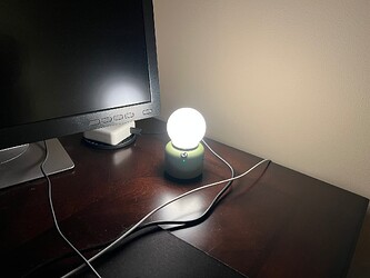
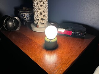
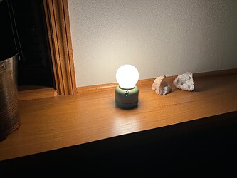
Here are some pics of how the light looks when being used around the house.
That’s it, all done!!! It was a fun project to work on. The toggle switch is so easy to use and the bulb creates a nice even glow of warm 3000K light. And it will definitely get used. My wife said it would look nice on her nightstand, but I think I will keep it for now.
Thank you for your interest!!! ![]()
You may need to make a version two, or simply an encore.
That’s the thing about wives, whenever they see nice things that you have, they will want to take it.
It’s a nice fun project and the result looks good! Congratulations! It’s unique, almost like a lantern.
Agreed, sounds like a great excuse to visit Japan and pick up some more canisters!
Thanks! It took a lot of hours to make and I’m glad it all came together in the end.
