very similar to newer version of MT-G2 EasyWhite (XFL10K)
attractive price in comparison to established high power emitters (XHP70.3, SFT-70)
weird naming of types
multi die (also somewhat similar to Sanan emitters it seems)
quite high turbo ratings (pretty sure these are somewhat conservative if you keep the earlier LED overcurrent testing document by Cree in mind), up to around 120-140 watts for XFL10K
only 5000K to 6500K 70 CRI (80 CRI only for smallest version XFL05K), but 80 CRI only available at Mouser for one whole reel. 80 CRI XFL05K is given a current of 1.65 Amps at Mouser instead of 1.75 Amps for 70 CRI variants.
green tints likely (no color binnings below BBL)
new footprint size (10*10 mm) for XFL10K (seems it could fit on MT-G2 board)
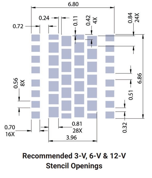
interesting footprint layout (more than two pads for each cathode/anode)
I am pretty sure these emitters are specifically made for the Chinese market to compete with Sanan/Lumenpioneer emitters. This could explain also the attractive pricing.
Good spot! There’s a lot of assumptions that the flashlight market is too small to be of interest to the big chip manufacturers, but they do seem to consider portable lighting a viable market.
These look a lot like the first-generation MT-G: lots of tiny dies with generous spacing between them, more space than the San’an emitters. Unless the optic is heavily diffused I’d expect the beam to be ugly as hell.
Ya I wonder why they went so over the top with it. I get that it has the weird solder pads but still. Seems unnecessary. Either way I will definitely not be following that if I ever reflow these lol
Thanks for making that summary earlier btw
It’s definitely a response to all these cheap sanan-type emitters getting more popular. Good for them, recognizing they should get in on that market. Why let other manufacturers undercut you when you can undercut yourself lol
No but honestly good for them. Quality control will probably be a little higher from Cree than from whoever makes these now. I’ll pay an extra $1 or 2 for a Cree over an SFN. And we’ll actually have datasheets
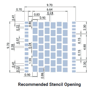
Strange stencil, I’m trying to understand why they’d do that…
Perhaps to control the volume of solder on the large footprint? Introducing the mask reduces the solder by, what, 15%? This would be for cost reasons or reduction of solder to prevent the die from “floating” on a solder blob.
Does thickness of solder have an impact on the thermal properties? Perhaps they’re deliberately keeping the layer thin to maximise thermal transfer?
Maybe it’s got no technical reason and is just to see who copies them?
Maybe, but lead free solder (especially Sn-Cu-Ag alloys) have a much better conductivity than leaded at the cost of crystallising weirdly after multiple reflows
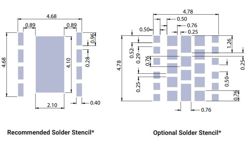
Its pretty standard for manufacturers to leave a little space or two or three in the middle of the stencil somewhere, I think to allow the solder to flow into the empty space, but cree kind of goes over the top with it.
This isn’t unique to these new LEDs though, heres the xhp70.2-