The white flats don’t play nicely with FET drivers, they get overdriven due to their low forward voltage which results in a huge loss of performance and possible damage. In theory it’s possible to manage this using high resistance batteries, but i don’t know how effective this is in actual practice.
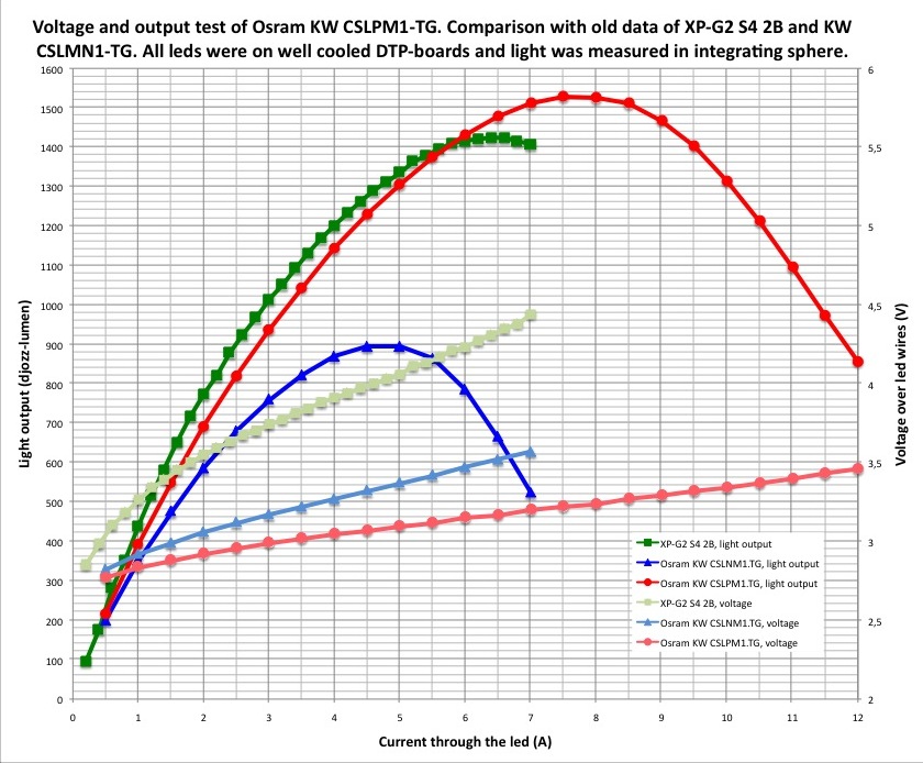
Here is the 2mm output graph that Djozz produced showing the output dropping above 8A: https://farm5.staticflickr.com/4874/46015321372_cee6f5b38d_o.jpg
It’s taken from the first post in this thread: OSRAM CSLNM1.TG & CULNM1.TG 1mm², CSLPM1.TG & CULPM1.TG 2mm²
The 1+5+FET means that the driver is fitted with 6 x 7135 chips and a FET, and controls 1 of the 7135s independently from the other 5 for low modes, then adds in the other 5 x 7135s as a group for medium to high modes, and can then add in the FET for modes from high to turbo.
ONE7135 means 1 of the 7135 chips is on and letting through 350ma, ALL7135 means all the 7135s are on, and as there are 6 they let through 6x350ma which is 2100ma, or 2.1A. Turbo means the FET is fully on as well so drawing maximum power from the battery which i’d guess is approx 6-8A depending on the battery.
The 4 and the 11 relate to brightness levels 4 and 11 out of however many the driver has been programmed with, but i don’t know how many that is.
But given the sequence - I think 3,4 and 5 would be low, ONE7135 would be medium, 11 would be medium high, ALL7135s would be high and 17 would be extra-high, but i’d wait for someone more knowledgable to map those across properly.