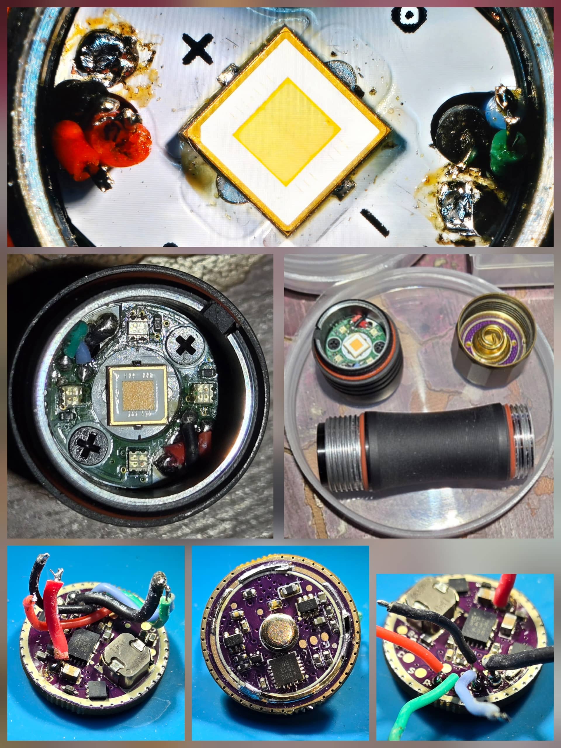
I have a KR1AA that had a broken driver contact ring. You can see the broken contact ring in the middle bottom picture.
I didn’t have any luck finding just the contact ring, so I ordered a driver from Jackson. I did not have him solder the wires to the driver, but wires were provided.
I ended up using my own 24ga silicone wires for the emitter leads, but used the provided wires for the Aux RGB. All of the provided wires need to be cut to the proper length.
I used the original wires on the driver for length reference.
It was a bit fiddly working in the tight confines of this small light.
I took lots of pictures to use as reference for wiring. Hopefully this is helpful if someone else is looking to do work on one of these.
It’s important the wires lay over eachother properly so they enter the head in the correct order. You can see how they need to be organized in the bottom left pic.
Top pic shows how they need to enter the head.
I didn’t get any pictures of everything as I was putting it back together, but it pretty much looks identical to the “before” pics.
All wires need to enter the head at the same time, which is very fiddly. I feel like I got really lucky there, as I only had to dig for one of them with my tweezers as it had gotten stuck in the wire hole.
The main emitter leads need to be soldered before the aux board is put in place.
The angle of the main leads can hinder the aux board fitting properly. I had to re-angle/re-solder the negative lead twice before getting the angle perfect.
Then the AUX leads get soldered. Red, Black,Blue,Green. In that order. You can see how they cross over each other in the middle left picture.
A cut off toothpick proved to be extremely handy to hold the RGB wires in place while soldering to the AUX board.
Success!
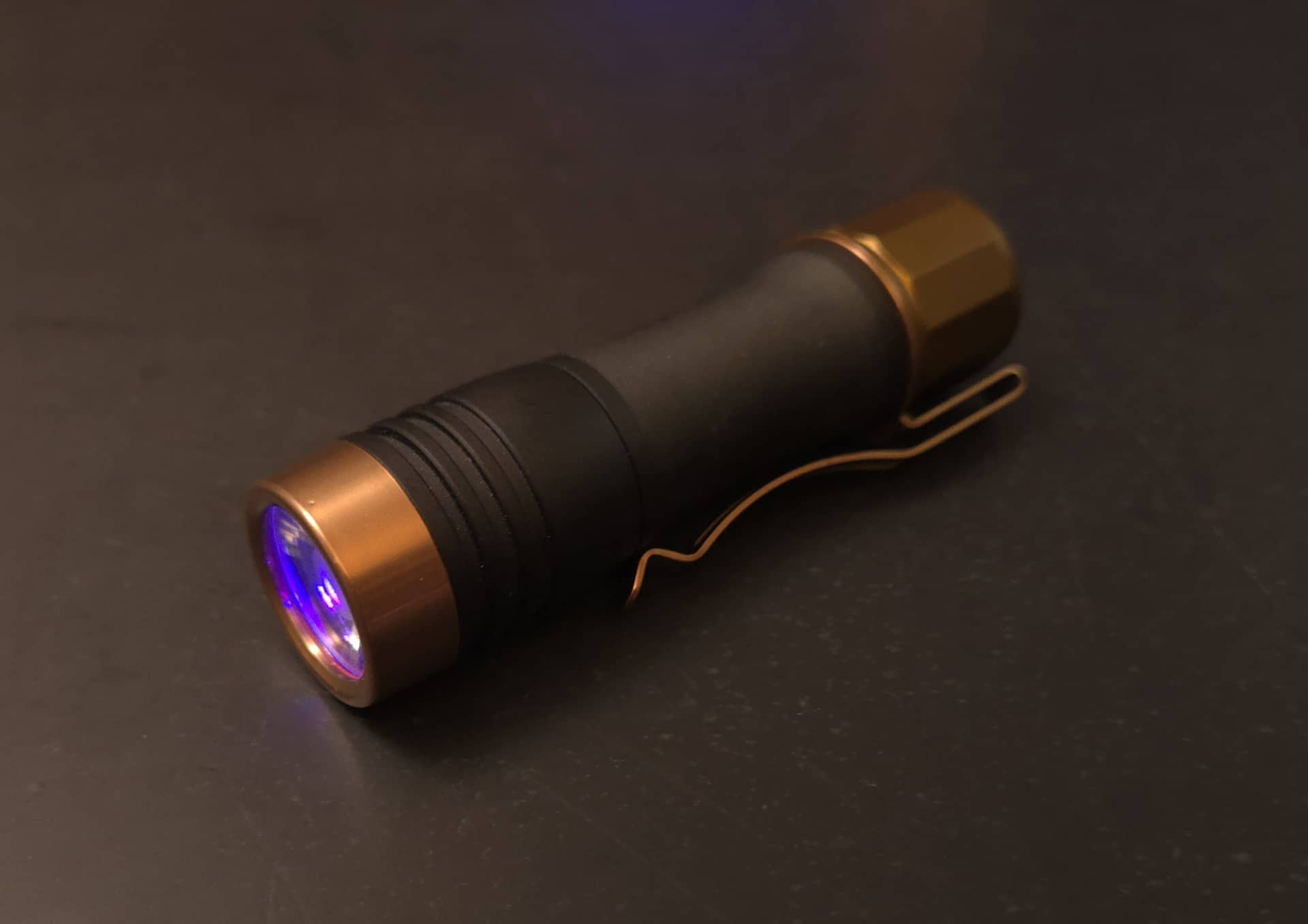
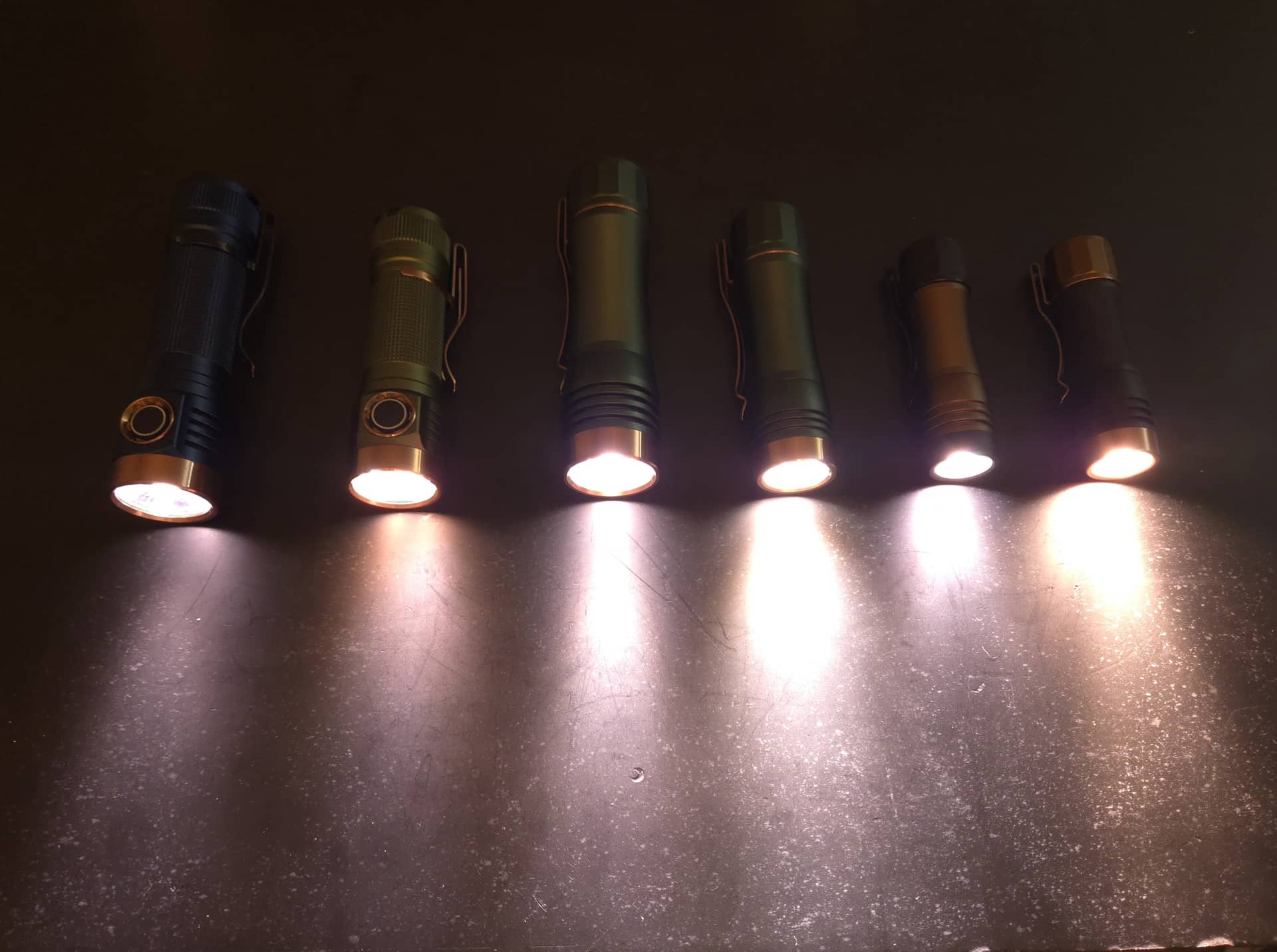
SFT-70 3000k
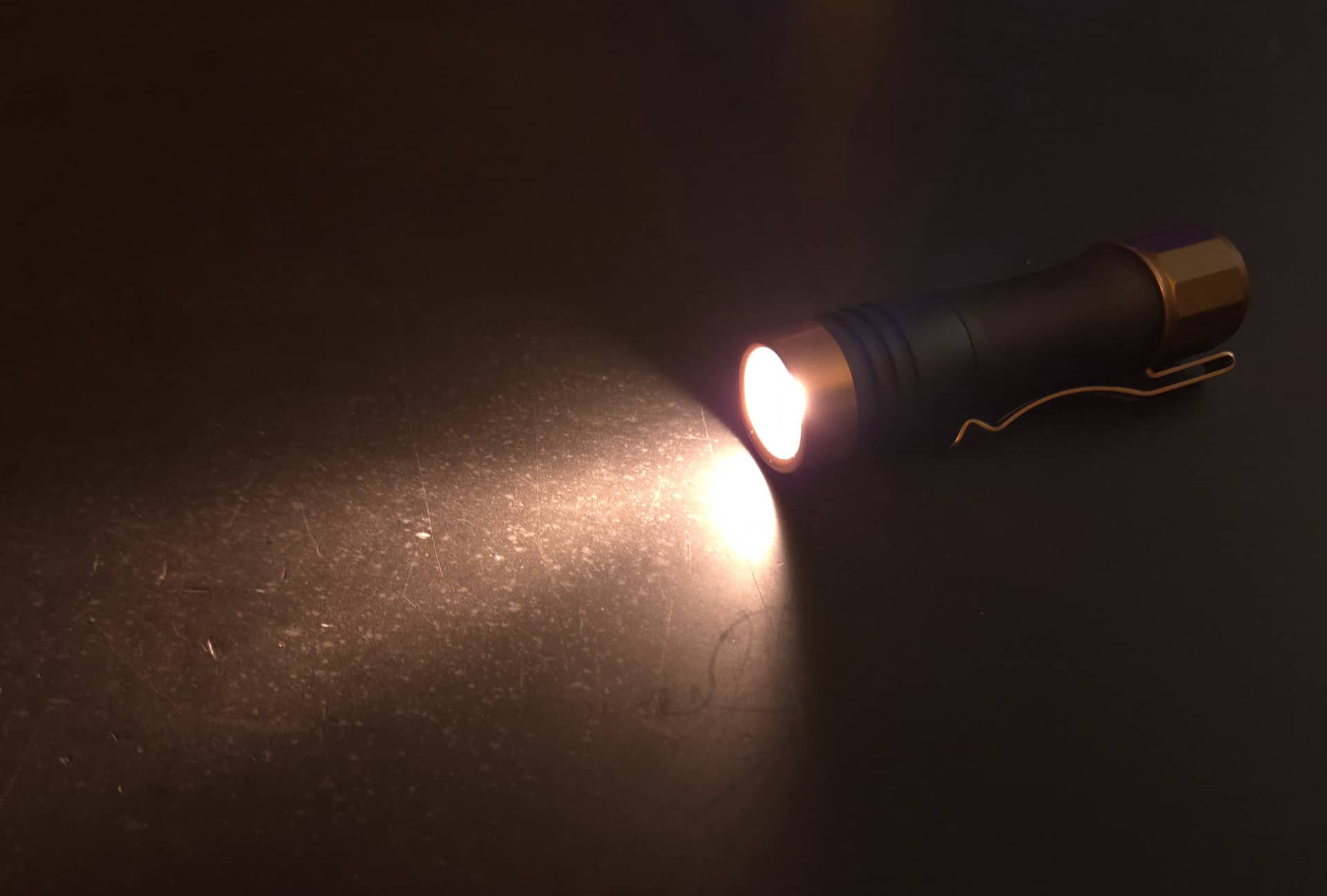

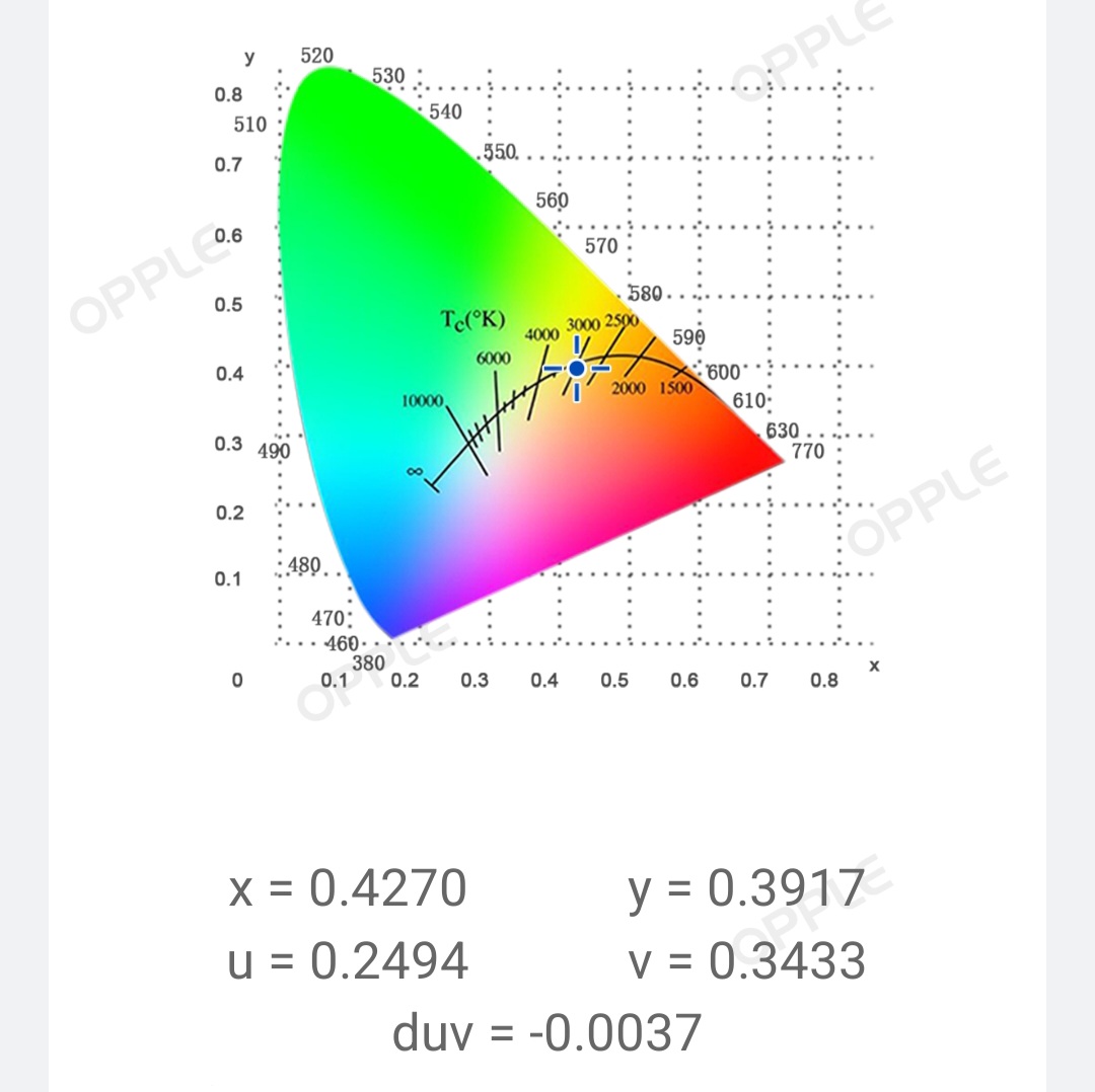
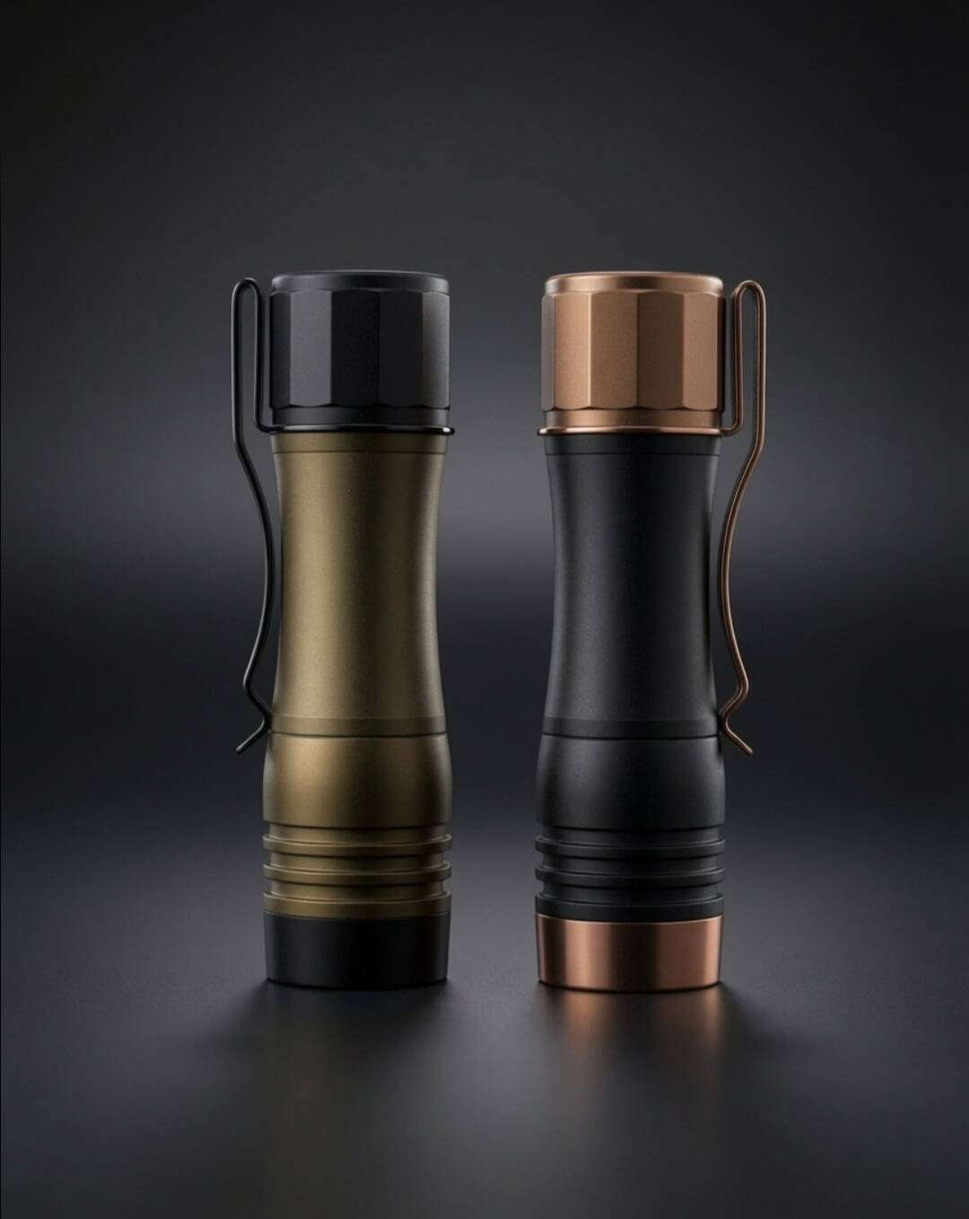
Enhanced glamor shots of the twins. Brown build has NTG50 4200k.
Hank collection
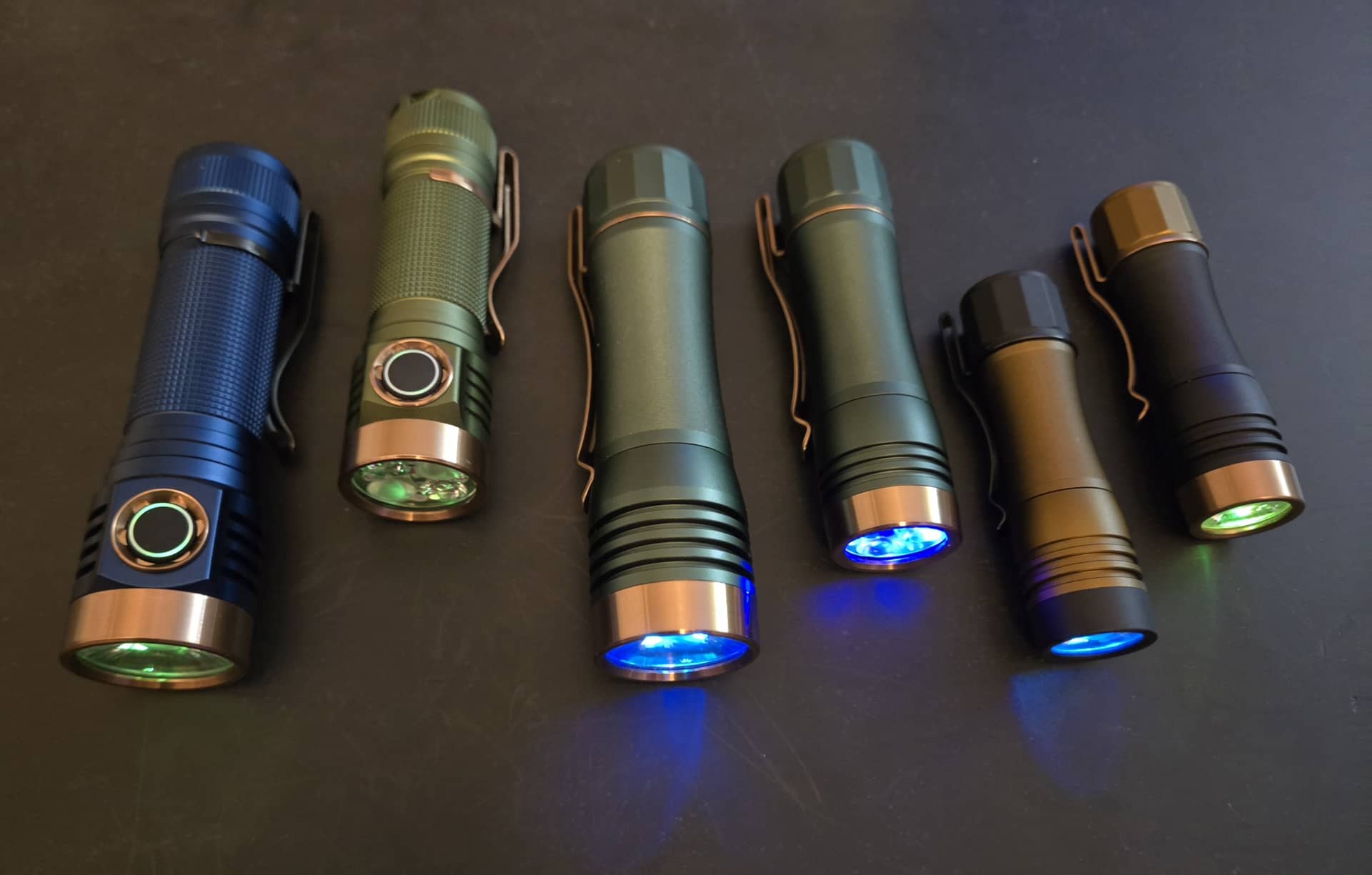
Hoping this helps someone in the future.

