I just got some 15mm DD boards in, the new ones, and I’ve previously ordered the kit of components for it from DigiKey. Now I can’t find the list that shows what goes where! Reading through the 47,939 pages of this thread is tweaking a killer headache.
I got 2 sizes of capacitors in that order, can’t exactly remember why.
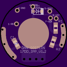
Is the 1 Uf or the 10Uf the one for this 15mm driver?
R1 is the 19.1k
R2 is the 4.7k
D1 is the diode
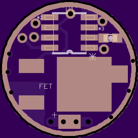
FET is the 2502 MOSFET
And of course the ATiny13A can only go in one place, whether upside down and backwards or not
So, the C1 is which variant? The 10Uf? If my beaten up memory serves correctly the 1Uf is for off time memory on the 17mm board.
There is a place for R4 that was intended to be a gate pull down resistor, this is now for the 1Uf cap. So this 15mm driver takes both the 10Uf (C1) and the 1Uf (R4). Whew!
I got spoiled to having the component list on the OSHPark listing with the board.
I built this 15mm driver for the Maxtoch SS 14500 light that looks just like this Brinyte Mod 65 With a freshly charged AW IMR14500 it pulls 4.65A and makes 941 lumens out the front. Not bad, hope it’s waterproof, cause it DO Get Hot!
Thanks man, I’ll look into the DRC commend, I’ve used it some but not every time. I did move tha via too tho, I changed all the cap/resistor pads to 0602’s and fixed the shorts. I shouldn’t order boards that I finish up late at night till I look at them the next day lol.
Email info in about something off topic man, found something really interesting I need your opinion on.
DRC is great but I stopped using it after I began trusting my own judgement. Risky, I know lol. It just started to give me the shits with the stuff it was complaining about, right or wrong!
what drivers here work well for purely low output? to give some context, I want a driver that will work really well for an amber XP-E(2) and will basically be just for around the house in the dark.
I don’t need crazy bright modes, but probably just 2 modes that are low output (relatively).
edit: maybe compatible with a single AA but also up to 6v?
Let’s get realistic. I’m not sure what your level of savvy is here, but you’ve put two esoteric requirements on there. You are referring to a driver which can accommodate a low Vf and is a buck/boost driver and there are none of those in this thread. A normal AMC7135 driver can drive an LED like that at low currents from an 18650 but efficiency will be low (60% or something). You won’t care, runtimes will be fine and heat will be low. We don’t have any boost drivers here at all, so look elsewhere (IOS, FT) for that if you need to run on a AA. For up to 6v you need a buck driver and Mattaus’s Knucklehead may be able to do it (nobody has tested it with a low Vf AFAIK) or when my QX5241 buck is ready that may be able to do it.
EDIT: and I’m in a bad mood, so please excuse my attitude
Gettin’ hot in here! >) you might have to compromise on the voltage requirement. A 500mA AA driver is one option but it won’t work with high voltage cells. A search through DX will give you some idea what’s available and Calvin at Ilumn can hook you up with a low power driver.
Single AA to 6V is too wide an input range I'm afraid. I've toyed with the idea of a single AA driver but they are just so hard to find the ICs for (in outputs that are relevant to us).
tterev3 provided an open source SEPIC driver based on the LM3410 chip. It requires two inductors but is highly efficient and will provide full regulated output from 2.7V to 5.5V (basically a single Li-Ion cell). Output maxes out at 1.5A but by changing the set resistor you can practically have any current you want up to 1.5A. I have a single mode design I was working on (no IC), but with an IC added you could get multi-mode going if you wanted.
I know the board has been cleaned up and there have been some revisions simplifying things for a better functionality, is the position marked with a “4” where the 1Uf cap goes for off time memory? This would utilize 2 caps, the normal 10Uf and the additional 1? Other than that I think I’m good to go on my first build with these new boards. This is similar if not the same as the new 15mm board, right? I did build my first 15 and it works great!
Can you write in copper? (ie can you put text on the top/bottom copper layer with additional text directly over it on the tstop/bstop layer [assuming no connections] and have that be your wording)? Not all of the component labels and stuff, that’s still screen, just like one big word (name of driver) in copper to look cool?
Sure, there’s nothing stopping you. Just maintain the design rules, as usual. It’ll be gold plated, I assume that’s what you are looking for.
EDIT: remember, you may not get perfect layer alignment. It may make the most sense to have the stop larger than the copper. Either thicker text or just a rounded rectangle or something. That way misalignment won’t result in stop partially covering your text = unattractive.
Ok guys here’s my first shared project. Its a 15mm driver specifically for nitecore AA sized (running 14500’s) piston drive lights, either the D10, D11 or D11.2. It runs a PIC MCU with open source code from tterev3 (available here).
Note this is untested as is but Everett’s looked it over and we both agree it should work. He has his done with the PCM air wired and I have a very similar board in mine but running an AVR MCU.
This is obviously a DD driver however after I have it up and running as proof of concept I’ll be updating it to a linear driver with selectable current via changing/stacking sense resistors, look for this to happen within a few weeks at which time the DD version will become unavailable.
As for the PIC MCU tterev3 would be happy to sell you them I’m sure (but not sure if he had any of the SOIC 12f1822’s in at the moment). You could also source the chip’s yourself and I can flash them for you for no charge (or you can get a PICkit3 for ~$35 and do it yourself).
This driver can be used in any e-switch lights that take a 15mm driver direct or piggybacked, simply connect SW+ to the bottom ring. Note bottom ring IS NOT GND, it’s the pickup for the piston (aka e-switch + input), if needed you can hook an external switch up from the top direct to MCU pin 2 if the bottom isn’t access able.
Also note obviously a lot of debate has happened around the cap location when using a FET, on the BLF drivers where the cap needed moved to before the diode it’s needed because a boost circuit is created and freaks out the FET (that’s what the gate resistor “fixed” before this was discovered). On this driver with the PIC MCU the boost effect doesn’t happen because of lack of a vdivide (the MCU has an internal reference for battery monitoring) so the cap needs to be in this location (after the protection diode), this can also be seen in Matt’s Medusa project. HOWEVER I did put extra copper so you can simply scrape another set of pads for a cap just to the right of the + input/output should go insist on having one.
Edit: board is labeled 4.0.1 however it’s technically 4.0.2 (name is correct, silkscreen is wrong). Also the via’s that are masked on the top but exposed (and labeled) on the bottom are for programming but using this version of 12F1822 its possible to use a SOIC clip (rewired from AVR)
 With a freshly charged AW IMR14500 it pulls 4.65A and makes 941 lumens out the front. Not bad, hope it’s waterproof, cause it DO Get Hot!