I found a wall pack from a 4 9v cell charger (http://www.batteryjunction.com/ipowerus-9v-charger.html) that is 12V 1.0A with a connector that match's the Dymo LabelMaker, but + and - are reversed. The Dymo is the odd case - so I cut the wire cord and patched them switched - worked great! They bought this @work, but decided to go with another Li-Ion cell format, so the charger and cells became expendable.
Nice find TomE.
Brian, an extension of the bottom board for an alligator clip with the lower jaw cut back would make that hands free.
Sorry for getting snappy guys! My mistake on that URL, of course one of them was suppose to go to the cutouts page :-(. I hope you can imagine my frustration after having people jump in to explain something I thought I’d linked to, heheh. I wish I made that double-links mistake less often, pasting the wrong URL is actually something I go back and fix a fair amount.
Moving on: the text is supposed to appear in the silkscreen layer, so if you don’t see it then it’s definitely not there.
Since I’ve been off the forum for a bit I missed MRsDNF’s conversation with Dan. I never did get in touch with them like I said I planned to at the time. I’ll drop them a line and see if there’s an easy fix for the way I was doing it. The “cutout” text is recommended specifically for closed shapes, I don’t think that matches what I used, so we’ll see.
Good to see you back wight tterev has a new thread on buck design you might appreciate. I look forward to seeing how it unfolds and hopefully demystifies some of the aspects of buck drivers.
Thanks RBD! I hopped back on just in time to see that thread pop up, but I’ve only skimmed the OP yet. The more design discussion that happens around here the better for all of us.
In the meantime please mark a caution on all of my PCB adapters in your OP until we get things sorted out on them. TIA
I honestly found that I liked them the way they were as I could machine them to what ever diameter I liked internally. I've been stepping them so the driver sits inside. No stress wight. 
I don’t think we have a convention for designating the offtime cap on the silkscreen. Maybe “OTC”?
agreed
Lead on mc duff. OTC works for me
Just a little something I’m working on for the holiday’s (a huge learning experience for a board with absolutely zero components, no .sch at all)
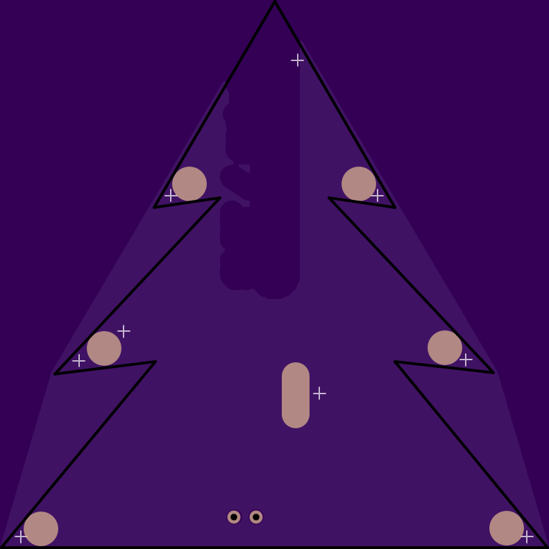
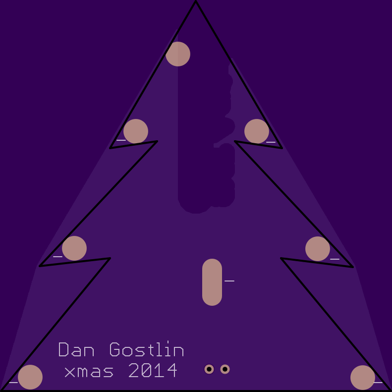
There is a slot in the top of this one (not rendered) and a matching board with a slot in its bottom, they fit together so it stands up 3D and has a bunch of LED’s on it. Unfortuniately its very expensive. I’m gonna consider doing a batch of 6 5” ones and selling 3-4 to get my 2 for free, just doing 2” (50mm) ones its $40 worth of boards.
Any chance of getting the BLF 17DD-Zener Revision 2 driver updated to the latest level, like the BLF 17DD v1.0?
couple of things:
- OTC support
- remove old design resistors
- add a rev # to the silk screen
Can Mattaus do this on his own or does he need help?
He certainly knows how to handle those things, I can’t speak to whether he has the time and inclination however! ![]()
Warhawk-AVG may already have the BRD and SCH files for that project. If neither of them is able to make the tweaks and you are looking to get it done soon I could also drop Mattaus a PM and see about handling it (I do not have the BRD/SCH files).
EDIT: nope, see post #1337. Warhawk-AVG doesn’t have the files.
It would basically be the same thing, since you don't use the normal diode anyways on the zener mod. You can run fast PWM with it, just jumper over the gate resistor if you feel like it. The "RMM" version has the OT cap pads already (see Matthaus's OSH profile).
The only revision you could make would be to get rid of the gate resistor. Whoever does the new ones, please don't put solder mask over the BATT+ vias.
You mean unmask the other half of the little area where the 4 vias are now in the current boards?
IMO you should strongly consider this approach. IMO the means don’t justify the ends when it comes to those PCBs. A paper circuit should be over 10x less expensive, “correct” xmas colors, and allows for customization beyond LED color during assembly. Also if it turns into a hit w/ the family in December you can manufacture more quickly - unlike w/ OSH Park!
No, just make it like the earlier versions of the boards. The "1.0" versions have masked vias on the BATT+ and along the outside ground ring. I prefer to be able to fill them with solder if needed. Does it make a difference? I actually don't know.
I see the difference you are referring to now. Solder-filling shouldn’t make a difference based on the small amount of testing I’ve seen, but exposed +/- vias aren’t really hurting anything either. As you pointed out RMM17DDZ_V2 already seems to have all the bases covered though, I see no big need for a new version. It could be cleaned up by removing resistor pads which need to be jumpered, but that’s about it.
I don’t have the zener builds
I think I agree - it's darn close to a zener 17DD latest greatest, just that R4 should be jumpered and R5 left blank?
Why aren't these OSHPark boards listed in the OP? Richard - are those 2 RMM boards the ones you sell? Did I miss discussions on these?
Wow! Mattaus has been a bizy boy - he's got like 6 pages of boards with the RMM 17's on page 3  .
.
6 pages and remember that he removes defunct stuff, so he’s even more prolific than it looks.