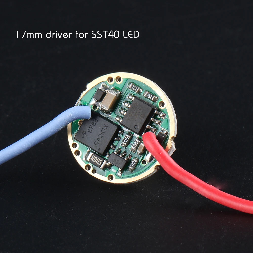
Speaking of regulation, it's either regulated or not. So, if the driver is regulated that's what it will do. Linear or buck drivers cannot boost voltage, only reduce it. In the case of linear drivers like the one you linked above (found it here too) or Simon's newer drivers (all of them are dubbed or advertised for SST40, by the way), any excess voltage and current is burned by the driver in its MOSFETs; the driver senses outgoing current in its sense resistor, this happens because when current goes through the resistor it causes a voltage drop in the sense resistor terminals which is amplified by a current sense amplifier (it amplifies the sense voltage at the resistor terminals) and fed into the MCU. The MCU uses this information to precisely adjust the MOSFETs' VGS; this controls the resistance of the MOSFETs to the flow of current, i.e. uses the MOSFETs in linear mode, and this way it can precisely control how much current is flowing (think of electricity like a gas, and imagine the MOSFETs are like a gas valve, and the MCU is someone who opens the valve just enough for the required amount of gas to flow). When less than the maximum allowable current is sensed, the MOSFETs are of course driven “all the way” or in saturation mode (in this case the amount of gas pressure is not enough and the MCU just fully opens the gas valve).
The newest single cell 8A buck driver from Convoy is a very smart choice, because it is a switching driver. This means it does not burn excess voltage (times current which is power) as heat in the board, instead it uses a buck converter to efficiently and precisely adjust the voltage to the led for the required amount of current to flow (sensed with a sense resistor, of course). The reason for such a powerful buck converter in limited space is that it is meant for single cell operation, and thus it is not necessary to employ a much bigger inductor which would be required for it to work with 2S cells input.
If you can swap sense resistors in drivers, adjusting the sense resistor value has a direct effect on the amount of current the driver handles. As an example, Simon's Ø22mm 6A drivers (this or that). They are meant for 6A maximum driving current and employ a 10mΩ sense resistor (R010); this means V = I × R = 6A × 10mΩ = 60mV of sense voltage (in case you are wondering, the current to the emitter entirely goes via the sense resistor). Knowing the sense voltage we can re-calculate the sense resistor value for a different current. Since you'd like to increase current, you could stack another sense resistor atop the one in the driver (more conductance) to raise the current. How much? Well, for +1A let's do the math: R = V / I = 60mV / 1A = 60mΩ; this one was :-D easy. On top of this, I just found an advertisement which precisely sells 2010 imperial 62mΩ sense resistors here, which is super close. Proper driver cooling is recommended if raising its limits, namely if you do away with temperature regulation (removing the onboard NTC). I can understand, though, that modifying a driver requires certain tools and skill.
Back on CULPM1.TG issues, I find somewhat surprising these underperforming CULPM1.TG units. Must be some bad bin. Got them from Shenzhen silver ingot Technology Co., Ltd. in AliExpress?
By the way, the CSLPM1.TG is about less than half the price of the CULPM1.TG, what gives? ![]()
I have a thrower with a CSLPM1.TG driven at 6.5A or so, I built it for someone else but needs a repair. Nice to see that I chose a proper driving current for it.
