OSRAM IR SFH 4715AS + Luxeon IR short output test - Cu MCPCB vs. mosX

On BLF there are tests available for pretty much every white LED and even some UV/color LEDs, but I didn't see someone actually test IR LEDs, so I did short test of relative output and forward voltage of OSRAM SFH 4715AS.

I used standard 1010 luxmeter which isn't the best choice for measuring IR LEDs, but if it's close enough to LED,it's able to detect IR light just fine. I can't measure absolute light output in mW with this luxmeter and method, only relative output (actual mW output vs. current still can be calculated from datasheet), but this is still very useful to see the limits of this LED.

Forward voltage was measured with 4-wire Kelvin method, to eliminate errors due to wires voltage drop.

I used two LEDs on two different MCPCBs; first one is non-DTP XP copper MCPCB mostly used for this LED among flashlight modders because it showed best performance:

https://www.fasttech.com/products/1611/10018154/3741200-20mm-copper-base-plate-for-cree-xp-series-led

OSRAM LED has footprint that's different form XP, but it still fits OK. Because ORSAM LED has thermal pad that is not electrically neutral, isolated MCPCB must be used.

Second MCPCB is mosX (short for MOSLED EXTREME), an aluminum board with thin ceramic (chemically grown aluminum oxide) as insulator:

https://led4power.com/product/mosled-extreme-mosx-ceramic-insulation-osram-oslon-mcpcb-20mm/

Footprint matches OSRAM LED footprint.

Test results are in table:

Lux values for second LED are scaled/corrected so that lux values are identical at low currents for both LEDs, this helps with comparing LEDs at higher currents. Correction factor is calculated from measurements at 0.4A and 0.6A.

Form test results it's visible that up to ~1A there is little difference in light output, but after that much lower thermal resistance of mosX board causes lower temperature rise of LED die and output declines slower compared to LED on Cu XP MCPCB. At 2.8Amps LED on mosX has ~15% higher light output compared to LED on Cu MCPCB.

2.8Amps is close to max. safe current for SFH 4715AS, both LEDs survived, but long-term LED reliability is not known.

What's interesting is that performance difference between two boards is quite visible for LED that has very large thermal resistance of 9 C/W, both boards have fraction of that, but when LED die reaches high temperature, it seems every additional C has significant negative impact on light output.

____________________________________________________________________________________________________________________________________________________________________________

Edit: 11.06.2018. Luxeon IR vs OSRAM SFH4715AS test

I finally tested Luxeon IR LED, specifically L1I0-0850090000000. Specifications look very similar to SFH4715AS, same typ. output, footprint is completely the same, biggest difference is much lower thermal resistance - 2.5K/W, OSRAM SFH4715AS has 9K/W. This should mean slower output decline at higher power due to lower chip temperature increase.

LUXEON IR is available with three different lenses, 60,90 and 150 degrees. 150deg version could be useful for reflector an TIR applications, while 60 and 90deg are more useful for lens lights.

I tested 90deg, because 4715AS is also 90 deg, but lens on Luxeon IR is quite bigger, and radiation patterns are not the same, so I used correction factor to match relative output (assumption is that radiation outputs are the same, as datasheets say).

Here are test results for OSRAM SFH4715AS vs. LUXEON IR on mosX (lux numbers for Luxeon IR are scaled to match OSRAM at low currents, where difference in thermal resistance has negligible effect on output):

I tested OSRAM up to 4,0A this time, so both LEDs can handle impressive amount of current without failure. Also after 4,0A test, I checked lux numbers at lower currents again, to see if there is damage due to high current, and both LEDs had same lux numbers as before 4,0Amps, so there is no short term damage from high current,at least not on mosX board.

Form test results it's visible that up to ~1.4A there is little difference in light output, but after that much lower thermal resistance of Luxeon IR board causes lower temperature rise of LED die and output declines slower compared to SFH4175AS.

This test confirm that 2.8Amps is close to max. safe current for SFH 4715AS, over that there is almost no gain, and output even starts to decline over 3,20Amp.

Luxeon IR has higher relative output over 1,40Amps, difference is about ~7% at 2,80Amps, and ~11% at 3,40Amps. Also Luxeon IR has considerably lower forward voltage over 2,0Amps.

IMHO this should be stickied. There has been several threads about IR and information was somewhat lacking.

Would you consider selling IR leds on your store already mounted on your boards? That would attract people who don’t want the extra work and risk of doing the reflowing themselves.

Nice results. You get away pretty ok with a cheap non-DTP board but the Mosled Extreme board helps the output and probably also the lifetime of the led.

Thanks for the testing led4power. Not knowing anything about IR Lights would this work well for a night vision scope?

I wiill consider this (I have several LEDs available now).

There is one interesting IR LED from Lumileds which is almost a copy of SFH 4715AS: https://www.lumileds.com/uploads/685/DS191-pdf

but it has much lower thermal resistance, 2.5K/W vs. 9K/W, I will test that LED to when I find some time.

BTW, in that datasheet there is one interesting graph, which shows light output vs. temperature:

This graph shows IR LEDs output drops much more with temperature compared to white LEDs, around 0.5% per degree Celsius, white LEDs output drops 0.2~0.25% per C at >100C die temperature.

This explains why output gain with mosX is higher than what I initially expected (when LED has high thermal resistance such as 4715AS - 9K/W, board resistance in theory has less influence, because no matter how good board is, total resistance can't be lower than 9K/W).

In my test light output at 2.8Amp is 15% higher with mosX PCB compared to copper XP PCB, this means die temperature is about 30C colder with mosX PCB.

They are often used in IR illuminators for hunting, and for home surveillance systems.

I have that Luxeon IR at home for months now, as well as the tiny L1IZ-0850000000000 version, but did not find the motivation for a test yet comparing it to the Osram IR leds. I would not mind if that task is taken out of my hands :innocent:

Btw, annoyingly the 3535-size Luxeon IR led does not have an electrically neutral thermal pad, it is connected to the anode :weary:

Updated OP with Luxeon IR vs OSRAM SFH4715AS test.

Thanks for the new test! This Luxeon led will not shake the earth, but is does perform a bit better than the Osram led and the 0.16V lower voltage at 3A keeps it in regulation a bit longer on a 8x7135 lineair driver.

I was asked recently if I could build a torch to compliment this night vision scope conversion.
https://www.nitesite.com/dark-ops/
Hence the questions previously here.
Not having anything definitive to go on I purchased this led from led4power.
https://led4power.com/product/luxeon-ir-850nm-90deg-led-mosled-extreme-mosx-ceramic-insulation-MCPCB-20mm/
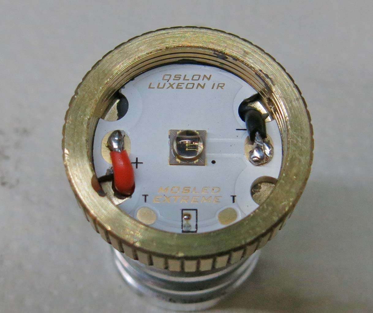
This was set up in a B158 pill. The B158 uses a 16mm MCPCB held down with a threaded plastic retainer and centering isolator.
The chosen led was only available on a 20mm ceramic insulated MCPCB so the pill area was machined out to 20mm.
The led wire holes were slotted and angled on the MCPCB and the matching holes in the pill were also angled to allow the 20 AWG silicone wire to pass through.
The MCPCB was glued to the pill with Original JB Weld.
There was a warning somewhere about these ceramic MCPCB’s being hard to solder to due to the heat absorbing abilities of the MCPCB. Having soldered dozens of DTP copper MCPCB’s I thought to myself no problem. Yeah right. I would confidently say if a couple of these MCPCB’s were placed in an oven and the oven turned on high that the oven would never get hot.
Needless to say after turning the soldering iron up to its highest setting and lots of flux used the wiring was successfully stuck to the correct places.

The driver used was the stock B158 flashed with TK’s renown Biscotti. This allows lots of options to suit different users requirements.
The original battery positive board was removed from the adaptor ring and the driver soldered to the adaptor ring and pressed back into the pill.
Why Brynite dont do this standard is beyond me. I have had no failures of the driver having modified around twenty of these lights for scope mounting on rifles using XPE2 leds.

The bottom of the head diameter of the pill was machined down for a couple of millimetres to allow the pill to recess back into the battery tube slightly as the ceramic MCPCB is a lot thicker than the stock MCPCB.

So how did it all work? I had no idea at first as you cannot see the light output unless the torch is held very close to a light surface in the dark. Only then do you see a faint red.
Not having high hopes as l had difficulty getting my head around that no visible light meant to me no light output.
I rang a friend who had lots of night vision toys asking if I could compare this torch to his Streamlight IR torch and Surefire white light and IR combo torch.
The result blew us all away. Put simply there was no comparison to be had. Even with the B158 in spread mode the difference was amazing.
One thing noted was running Biscotti with this configuration, 100, 35, 10, 1, 0.1, out to 150 meters there was barely a difference seen between the first and second outputs. The driver was left at its standard 2.8 amp output maximum output on high. The lower two settings did not work at all at 150 meters.
I will build two torches next and compare the visible difference between 2.8 amps and 2 amps.
The next testing will be with the new owner of this torch and his night vision set up.

Good and tidy work Steve! And I’m jealous of you lathe guys, I would have fiddled with extra o-rings under the lens and a bezel not fully closed, while you can just turn off a bit of the pill and have a perfect and professional looking solution :+1:

About soldering these boards, I went through the same process of awareness (I could not believe that my 80W solder iron beast was no match for the first VirEnce boards from Clemence). The solution is placing the board on the reflowing hotplate (even if the led is already pre-soldered) and while the whole thing is at reflow temperature, generously tin the solder pads so you know the solder connection to the pads are good. After cooling down it is easy with a hot solder iron to melt the (pre-tinned) led wires with the now already existing solder blobs.

Your thinking outside the circle is beyond me djozz. That would of been a quick fix using an oring under the lens :+1:
Yes, next time I will tin the solder pads before gluing the MCPCB to the pill. :person_facepalming:

Best method for soldering wires to mosX boards is to put pcb on thick piece of paper/paper towel, apply some solder on soldering tip and touch one of the big pads for about 15-20sec. First nothing will happen (pcb will "glue" itself to soldering tip),but as whole pcb approaches ~200C solder will start to melt just fine.After that you can easily apply solder on other pad, and solder wires without too much problem.

Soldering wires while mosX is already mounted is almost impossible (becomes possible when whole pill is at ~200C,but that's not good for LED).

Any seller of those mcpcb IR leds? I need import both of them to Argentina