Polishing a Turd (aka the Gearlight S2000)

It’s been a while since I did a build thread for you all, so here’s one I’ve been ruminating on for a while. I reviewed this light a few years ago for 1Lumen (along with the smaller Gearlight S1000) as part of “the most popular light on Amazon” reviews. Link It’s a 4 AA powered zoomie. It was pretty basic with just a screw-in hollow aluminum pill with a pressed-in shelf, telescopic zoom head, 3 mode linear driver, and a fake xm-l2. In short, it was expectedly bad, but had some endearing qualities.

I have a soft spot for zoomies, and decided why not do the right thing and spend hours and hours planning, trouble-shooting, brainstorming, making custom parts, add enduring much frustration and tool-throwing to make it into a viable, practical flashlight. I did this to the S1000 and it turned out okay, so why not? Hey, it’s only a bad idea if it doesn’t work, right? If youtubers can take dried up animal poo and make it shiny, I’m sure I take a terrible Amazon zoomie good. Here’s the basics:

Host: Gearlight S2000
Battery: 26800
Driver: 26 mm mountain electronics FET+7135
UI: Bistro
LED: L90 9090 size round die 50W on 26mm mcpcb

Problems:
Batteries. The light uses a carrier with 4 AAs in series. It’s roughly 120mm long and the 26800 is 80mm long so a roughly 20 mm gap to span (actually closer to 25) somehow between the base of the pill and battery top. I ended up going for a 30mm OD, 24 mm ID aluminum tube cut to length. I’ll braze this to the base of the pill.

Heatsinking: The stock pill is very hollow with a 2mm pressed-in shelf. It was bent from the factory from excessive pressing force (the tool mark was visible) so that had to be fixed. Im cheap, so I cut up some old PC heatainks to size and ground them down to round to fit snug in the pill then aluminum and will braze them in place.

More to come on this one as I get along (photos and such) so stay tuned!

2 Thanks

Here’s some progress on the Gearlight. All the parts are here! The LED arrived from the Orient this week, so I’m ready to start fabricobbling. Below are the L90 LED and the Mountain Electronics 26mm FET+7135 driver.

Step one will be fixing the lack of heatsinking by adding thermal mass to the pill. There’s a lot of room in there!

I’ll be filling up the space with an aluminum slug made from a couple of cut-up PC heatsinks (below), plus remains of the fake XM-L2’s MCPCB and the original pressed-in ‘shelf’ (you can clearly see the divot from the overzealous press tool) which is about 10 mm total thickness. This will be adequate mass for the roughly 50 watts of output.

Step 2 will be fixing the main issue with this project: Switching from 4 AA to 1x26800 li-ion. There’s a roughly 25 mm gap to span between the top of the battery and the bottom of the driver. I settled on extending the pill (which also adds thermal mass) using a piece of aluminum pipe. I cut it to length to fill in the space. The pipe is 30 mm OD, and needs to be roughly 29 mm OD to fit inside the battery tube, so I’ll grind it down on my belt grinder (later) then aluminum braze it to the bottom of the pill. The blue line is roughly (probably less than that) how much I’ll grind off to get a nice solid mating surface (also for beveling before brazing).

That’s it for now. Up next: Some hardcore grinding and cutting action, high-speed skin removal (hope not), followed by some fire and molten aluminum (hopefully no 2nd degree burns or unintended fires).

Stay tuned!

4 Thanks

Here’s some work I did over the weekend. Sometimes I forget how much work goes into this stuff (doesn’t help that I do it the hard way). The objective: Improve the thermal properties of the stock pill so it can accommodate a properly high output LED.

Step one: I took the cut-up pieces of heatsink and refined them on the belt sander a bit before brazing them together. I secured the parts in a nice aluminum sandwich in a clamp to keep them from shifting. That went fine, issue was that the ultra-cheap aluminum MCPCB didn’t want to bond to the rest of the parts, so I had a heck of a time getting good fusion. Took three attempts, with the last one the best. I’m using Bernzomatic aluminum brazing rods and a propane torch for this. If you haven’t tried aluminum brazing, it’s awesome and works surprisingly well. That’s a piece of mica fire-resistant material protecting my clamp.

Finished!

Next, time to mark the rough area I need to remove to get the billet to fit into the pill and get to cutting/grinding.

I used my small hacksaw to remove the big areas, and the belt grinder to finish (used 1x30 80 grit zircon oxide belts). When grinding with power tools, don’t forget that your eyeglasses aren’t a substitute for safety glasses.

The billet fits fine and fits flush against the back of the shelf. There’s some gaps, but that’s intentional since it will be filled in with brazing filler. Previously, I re-pressed in the shelf (after removing the divot and flattening the warped areas) using a 19 mm 1/2 drive socket and some blows with the 1/2 ratchet (what, I couldn’t find my hammer).

After brazing (which takes a lot of patience and heat and nearly giving myself a fire haircut), there’s still some gaps to fill in. I called it a night at that point.

I picked it back up the next day, completely filling in the gaps. This time the penetration is complete, and the pill is completely filled in now much heavier.

The marks from the socket are still visible in the shelf, but i’ll sand and blend those in (they aren’t deep at all).

Next step is the pill extension. It’s too wide, measured at 30.5 mm and needs to be roughly 29.5 mm to fit inside the battery tube, so off to the grinder. I mounted the tube on the handle of a skewer and allowed it to spin as I ground down the outside diameter, checking with the calipers every so often. Gloves are mandatory here unless you like getting friction burns and don’t like having skin on your fingertips.

Success! The tube fits in the tube fine, and after some finishing with a mill file to flatten the edges, fit-up looks good. I’ll bevel the mating surfaces before brazing them to get a good strong bond, but that’s down the road since my blowtorch died. The control valve retaining nut was previously broken and I fixed it with RTV silicone to keep propane from leaking out and catching fire during use years ago, but the fix wasn’t meant to be permanent, so the torch is down for the count.

So, on to the next item: The switch. The switch is a cheap, no-name Omten clone and seems to look okay and has a nice click action, so I may keep it, but the spring setup? I may end up bypassing the spring with solder wick and leaving it alone otherwise then fix it for real when (or if) it melts.

That’s it for now. Stay tuned for more. Next steps, fixing the switch, cutting a driver pocket, and brazing the extension to the pil.

6 Thanks

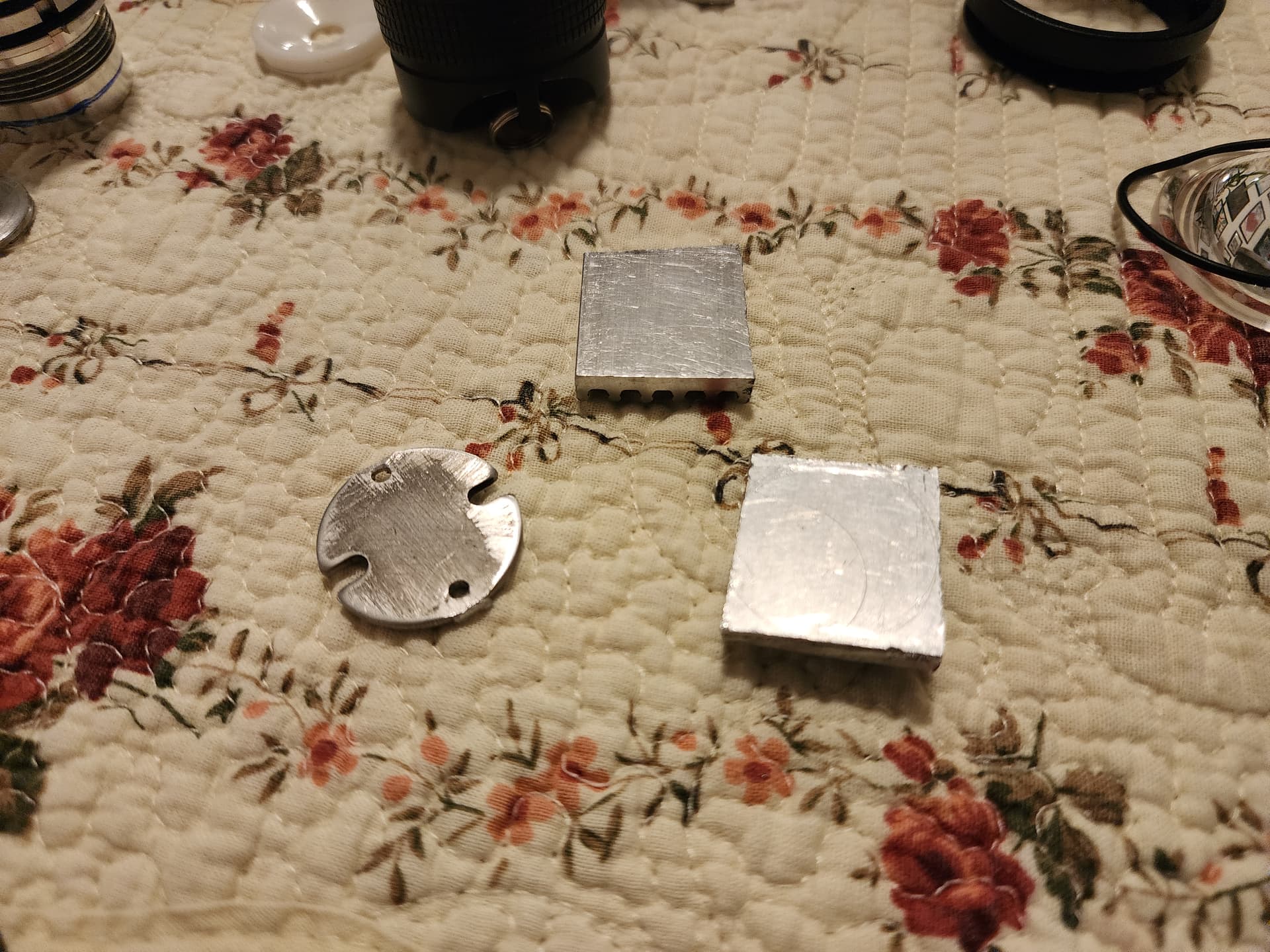
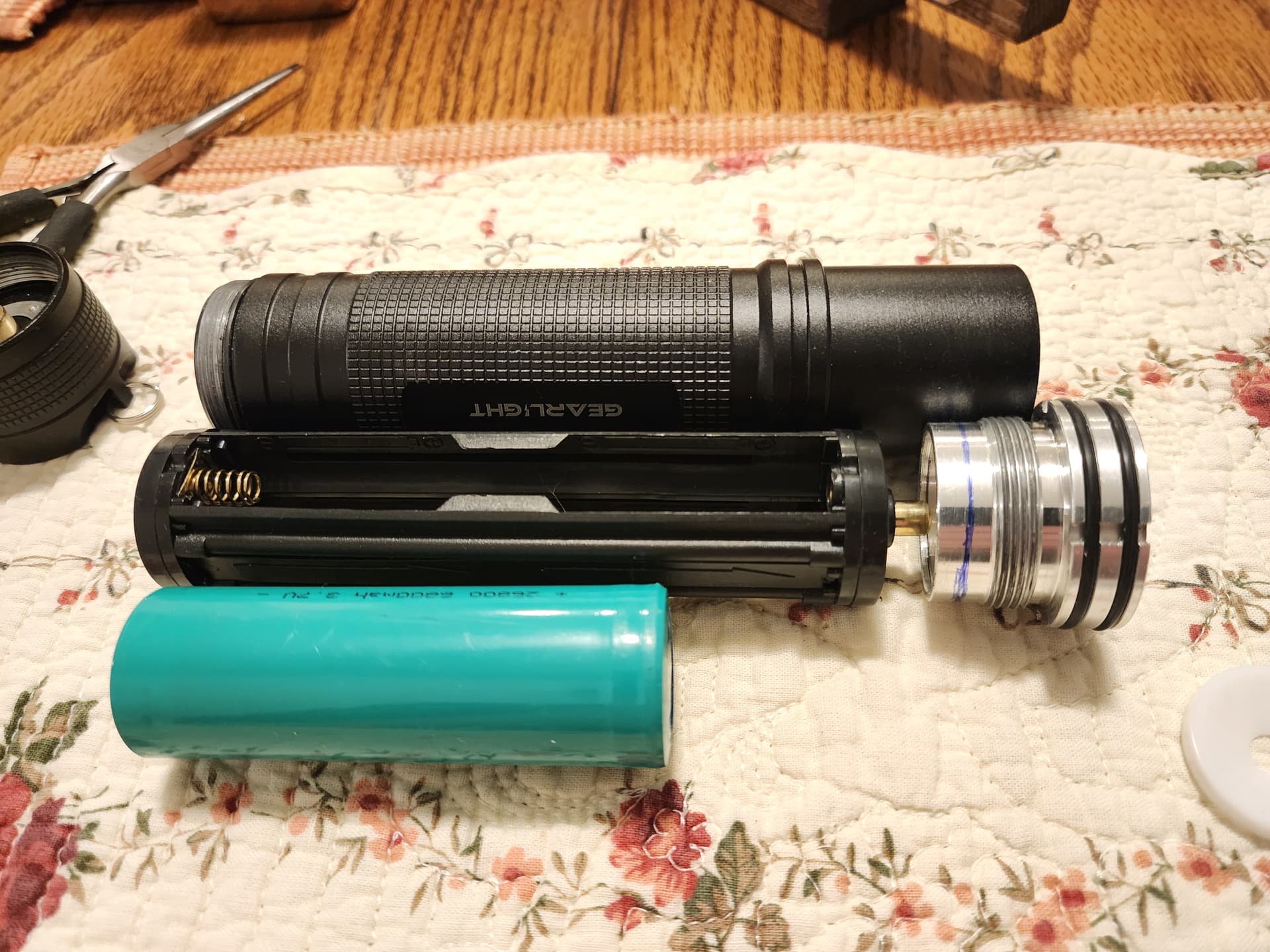
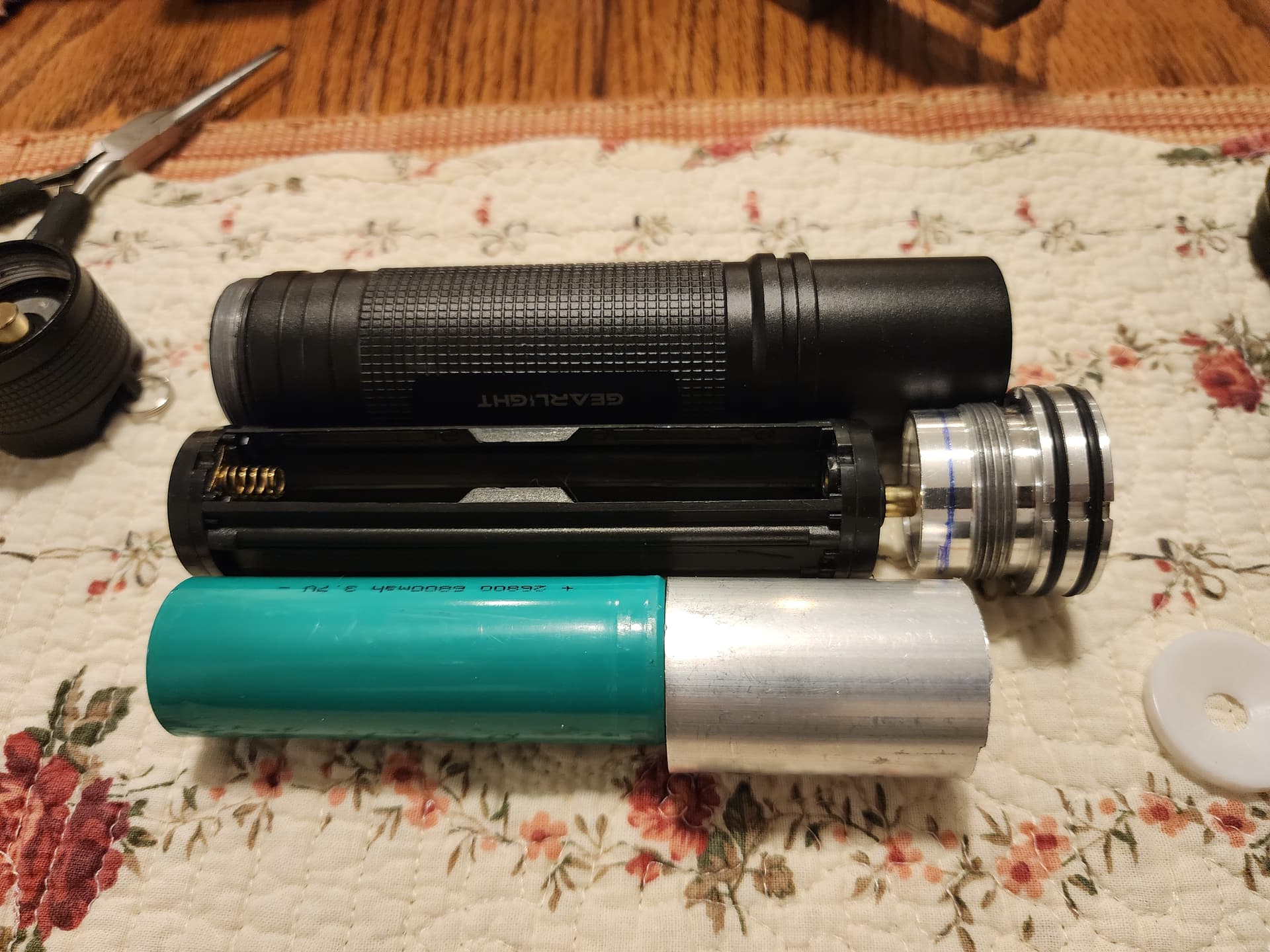
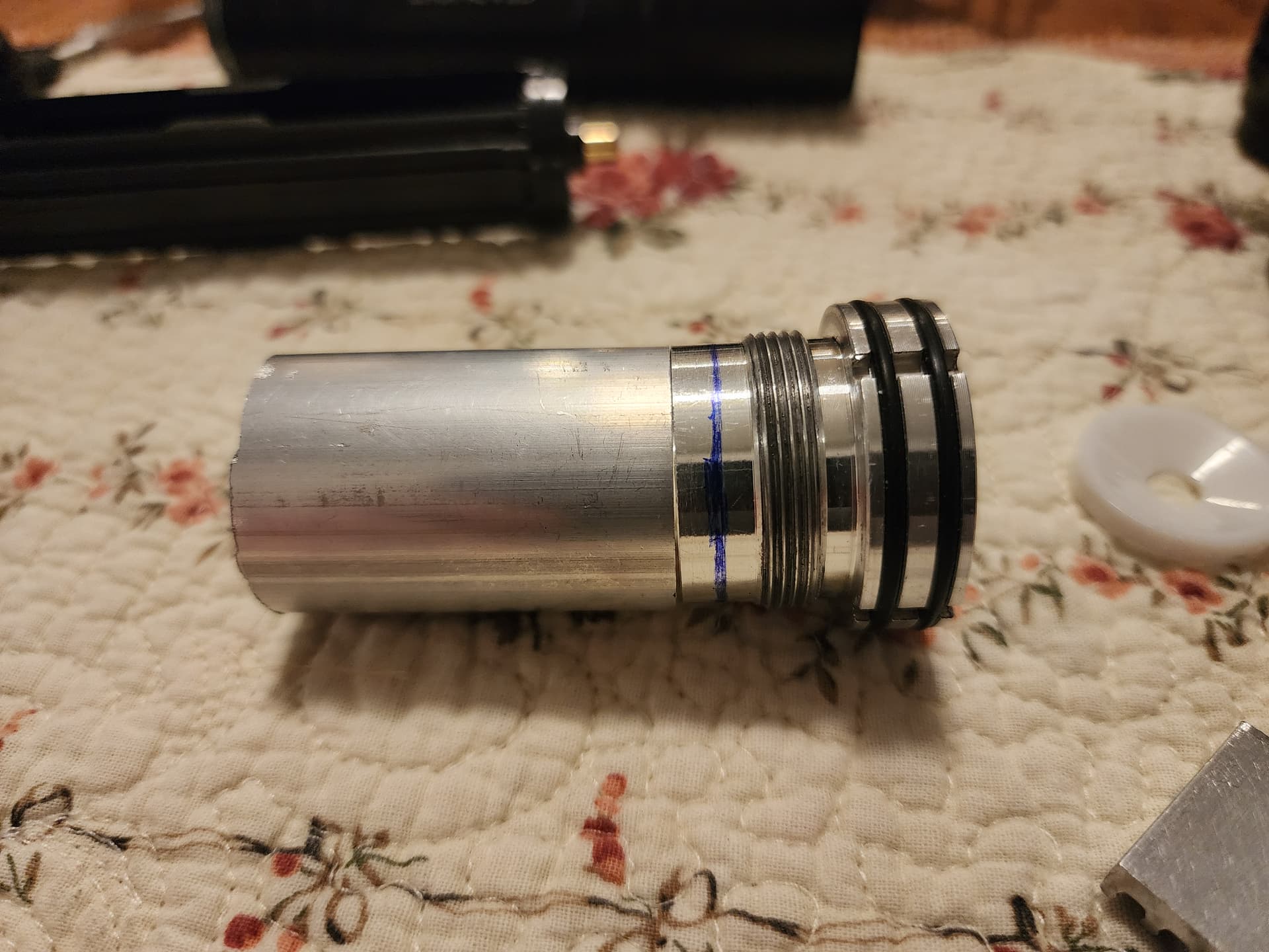
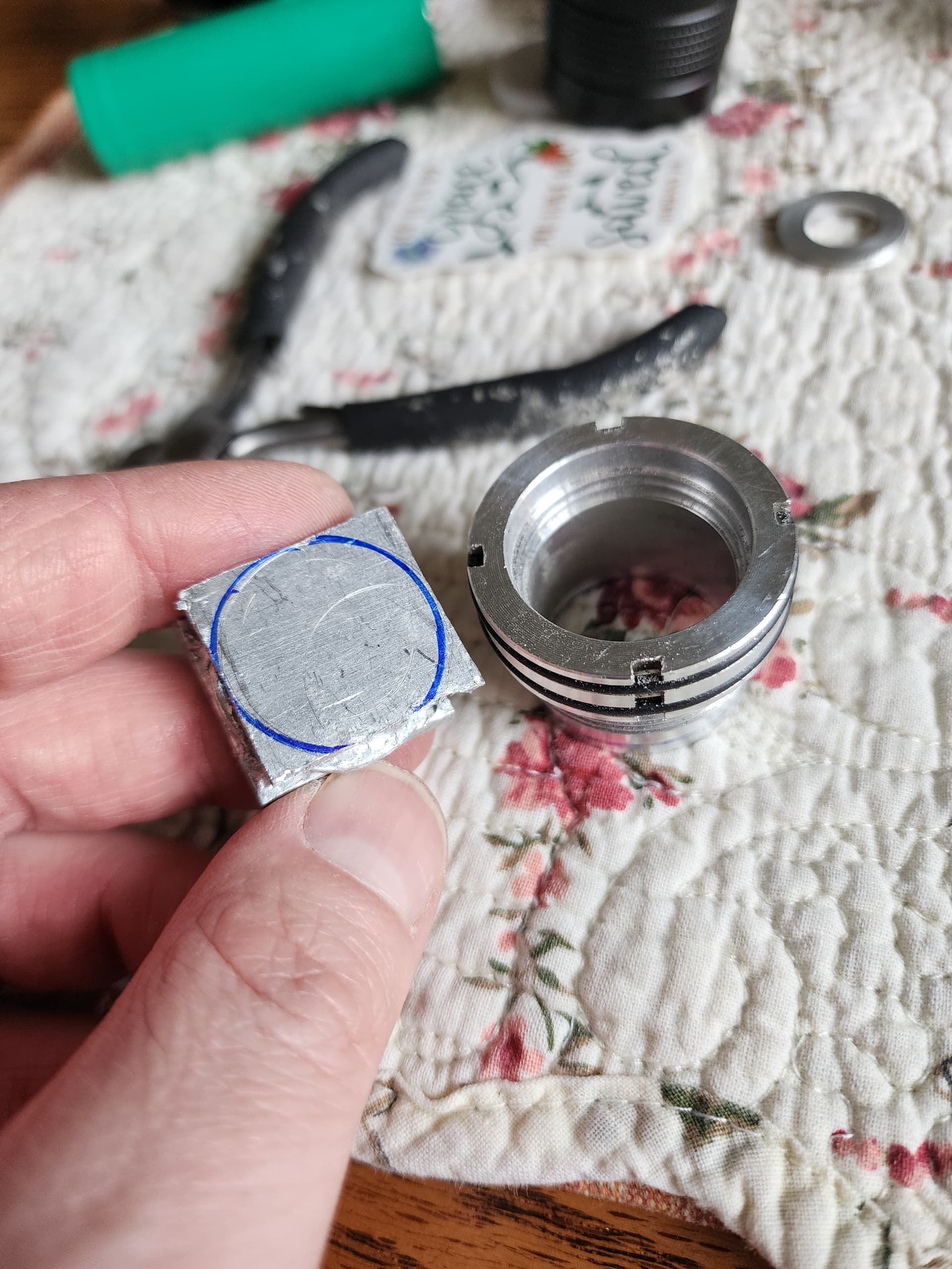
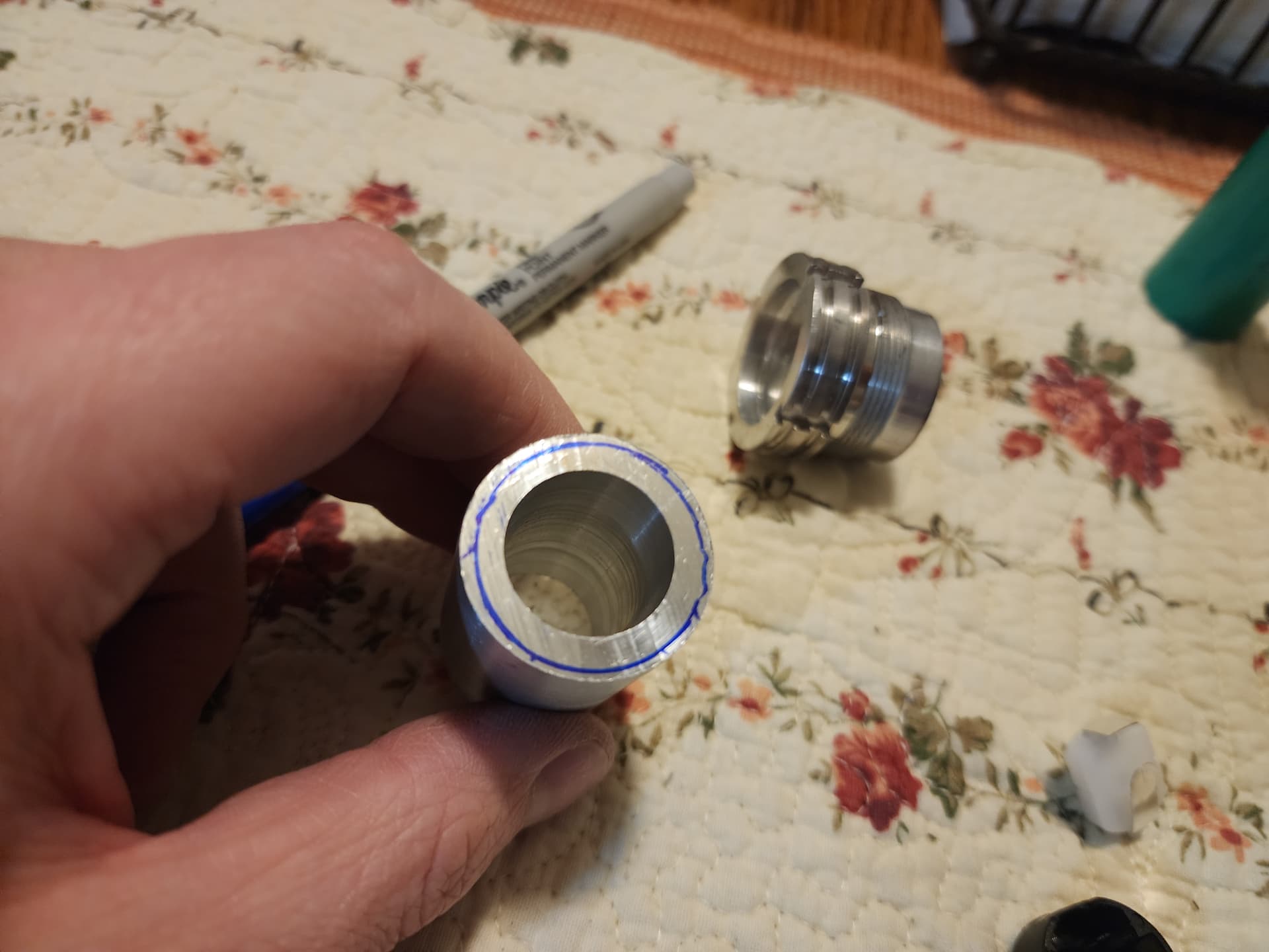
Progress! I carved out some time to hopefully finish the ‘turd’ so away we go! Next up is cutting the driver pocket. Since the aluminum stock is just…stock, it needs a shelf/recess for the driver ground ring. So, let’s make one. Step one is marking out the areas to remove and to make clearance. I laid the driver on the tube and marked out the edges of the driver outer diameter and the inner diameter of the ground ring. I set my calipers to the correct diameter and scribed a line that I filled in with a Sharpie.

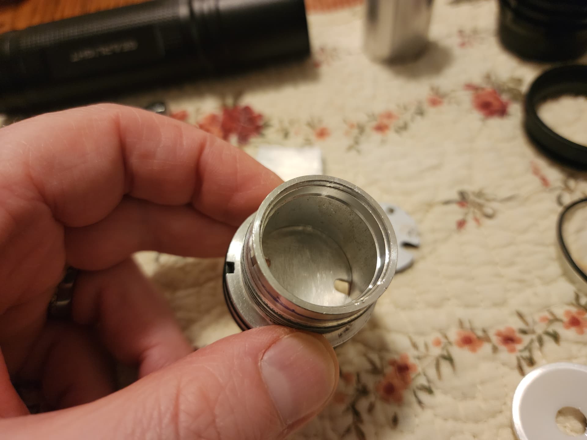
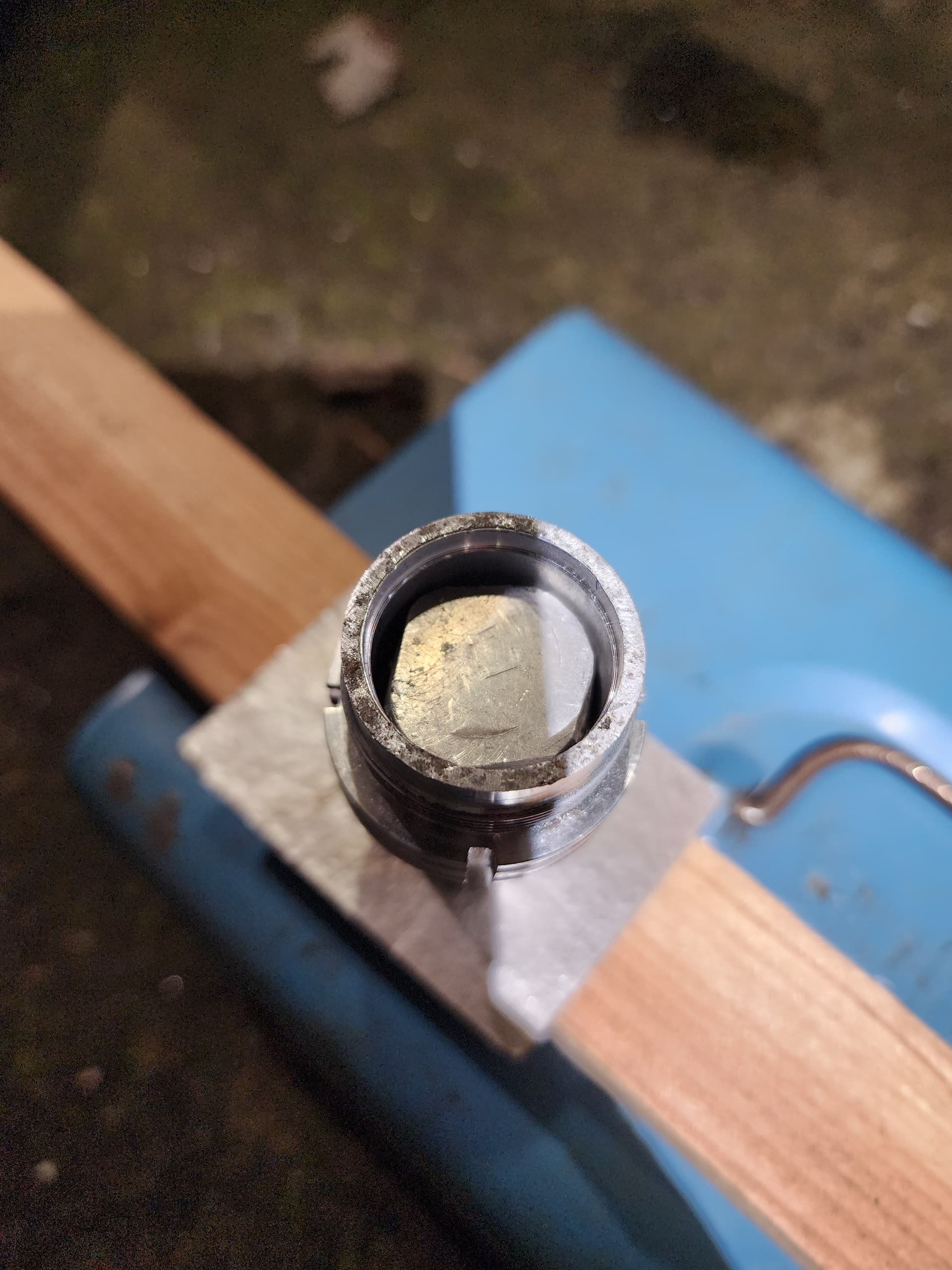
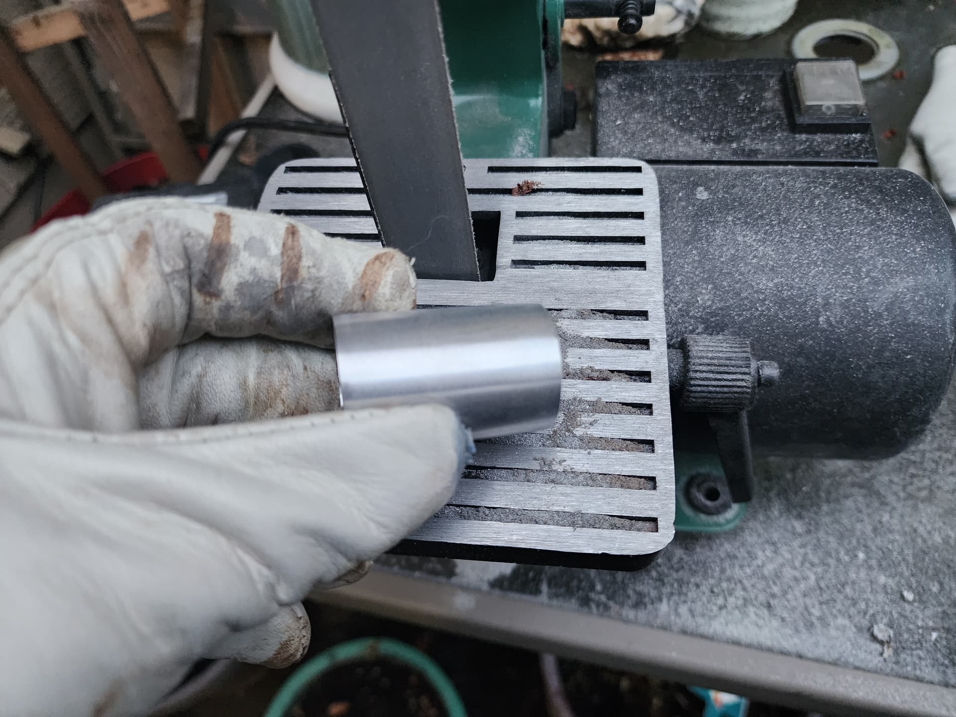
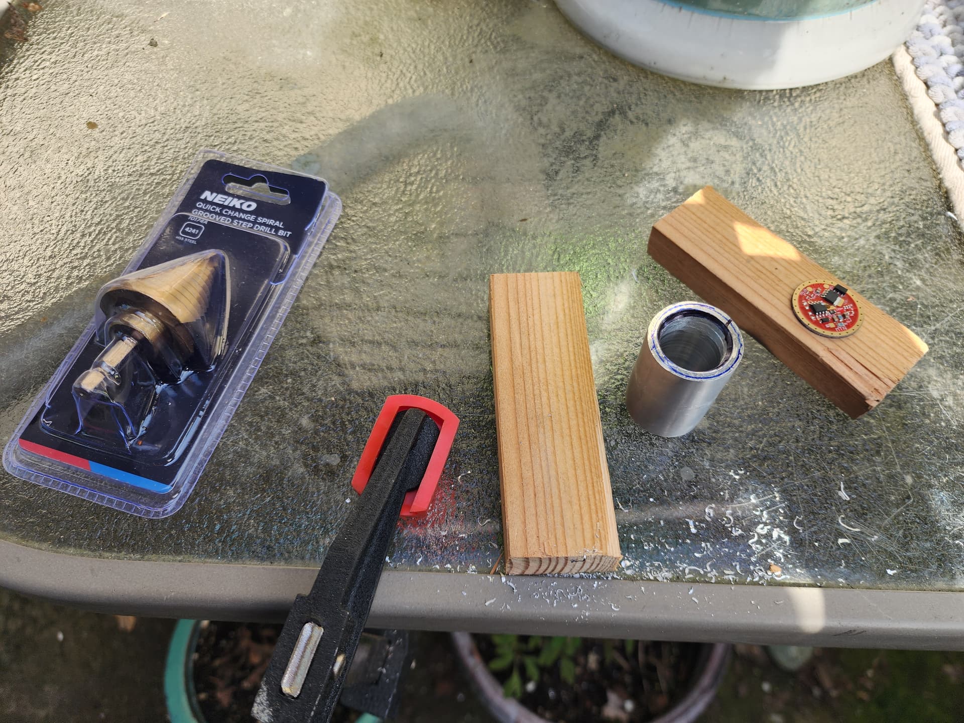
I had to break for a week, but step two is boring out the tube to a larger diameter before cutting the shelf. I tried this with my Dremel and some high speed cutters, then a sanding drum, and it was taking way too long, so I bought a step drill and had at it. I clamped the tube to the table and hogged out the inner diameter to about 24 mm.

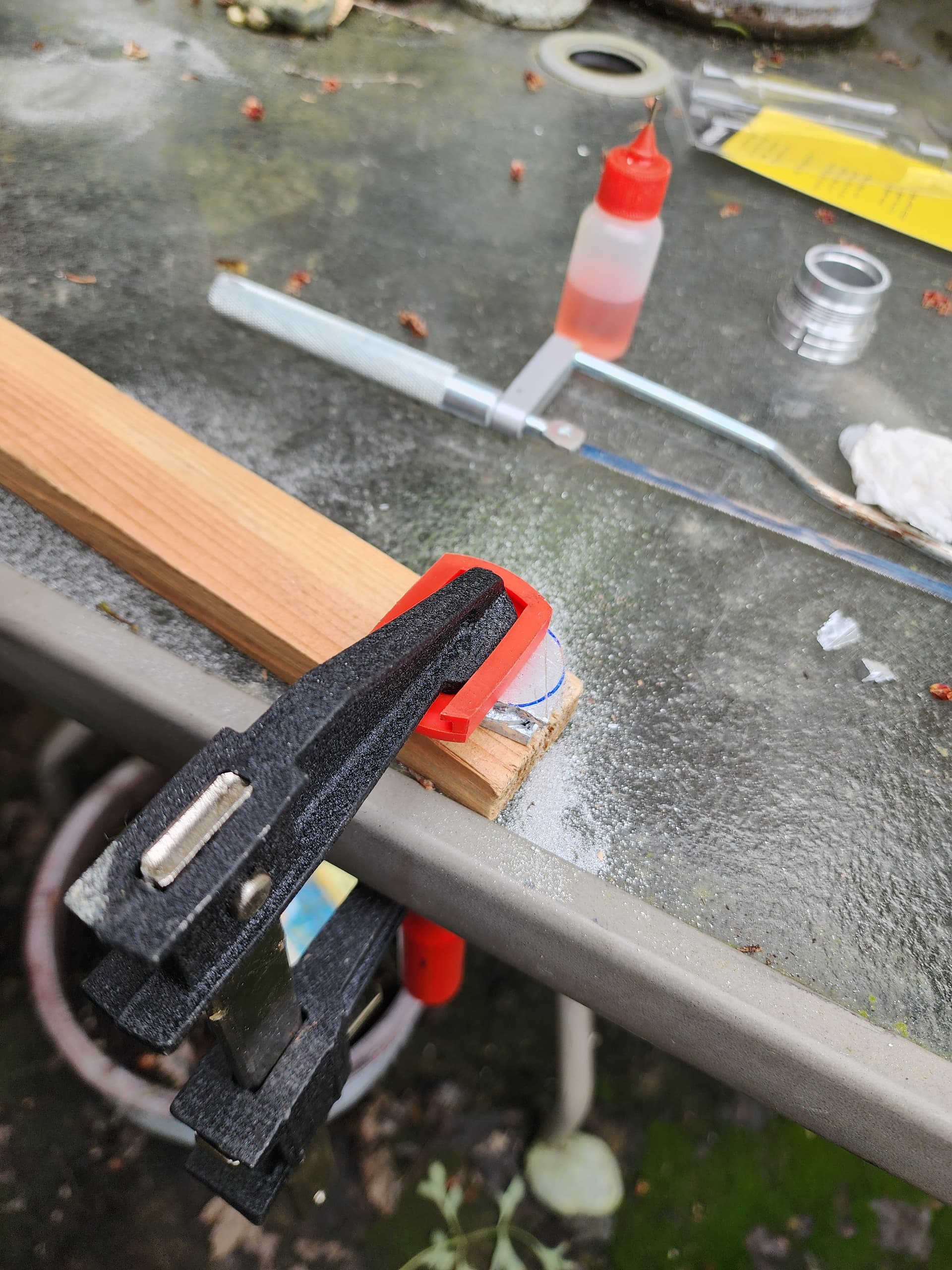
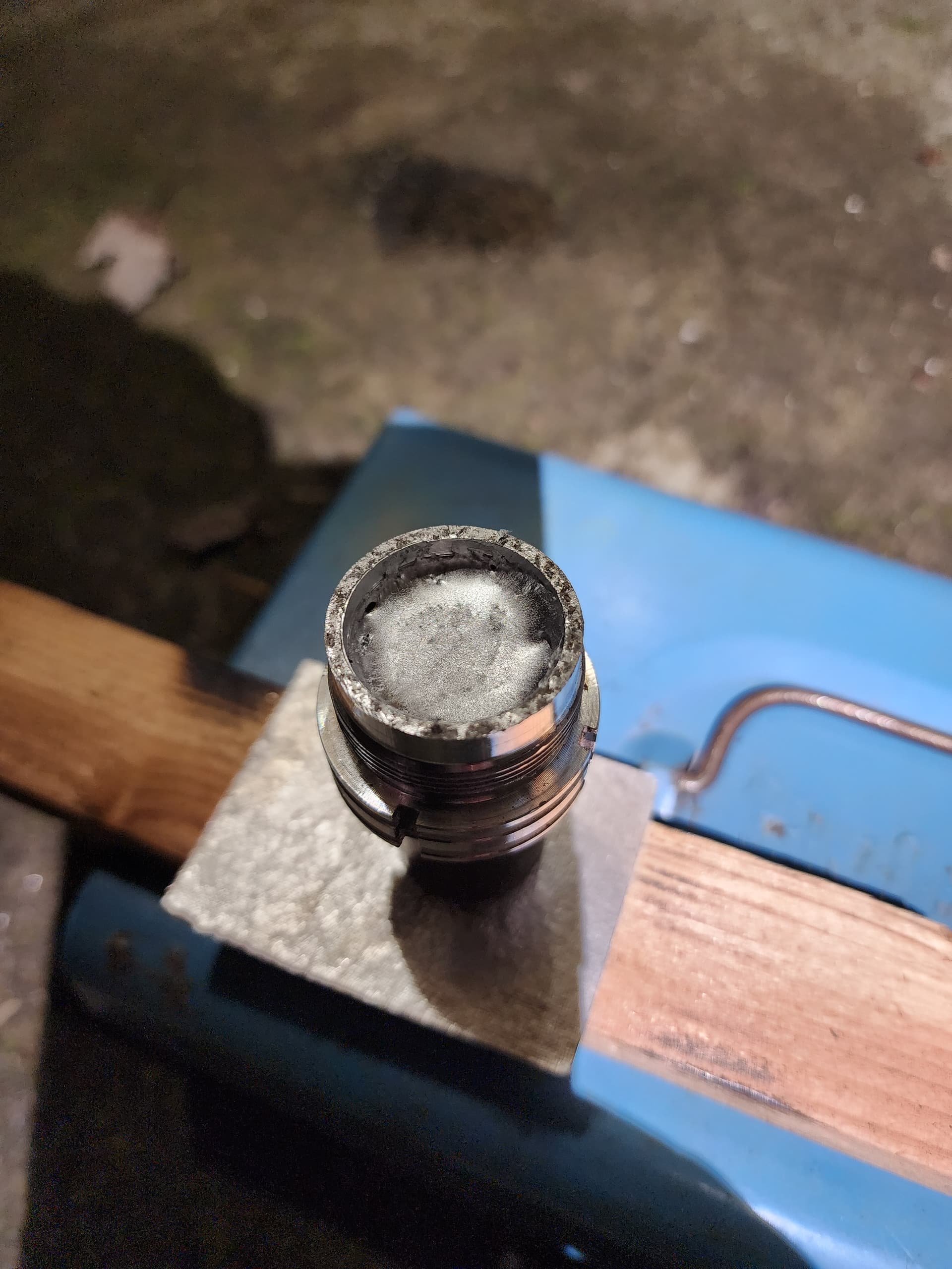
Once the hole was hogged correctly, I set to cutting the shelf. You see me with a glove on, well that went on after some high-speed skin removal happened when the cutter skipped and ran across my pointer finger knuckle. Ouch. This was a tedious, high precision exercise since getting it wrong means the driver doesn’t fit right and that could compromise the whole operation, so, yah, I took my time. Now I know why lathes are a luxury.

Also it’s important to check for continuity between the driver and pill during this process to ensure a good connection.

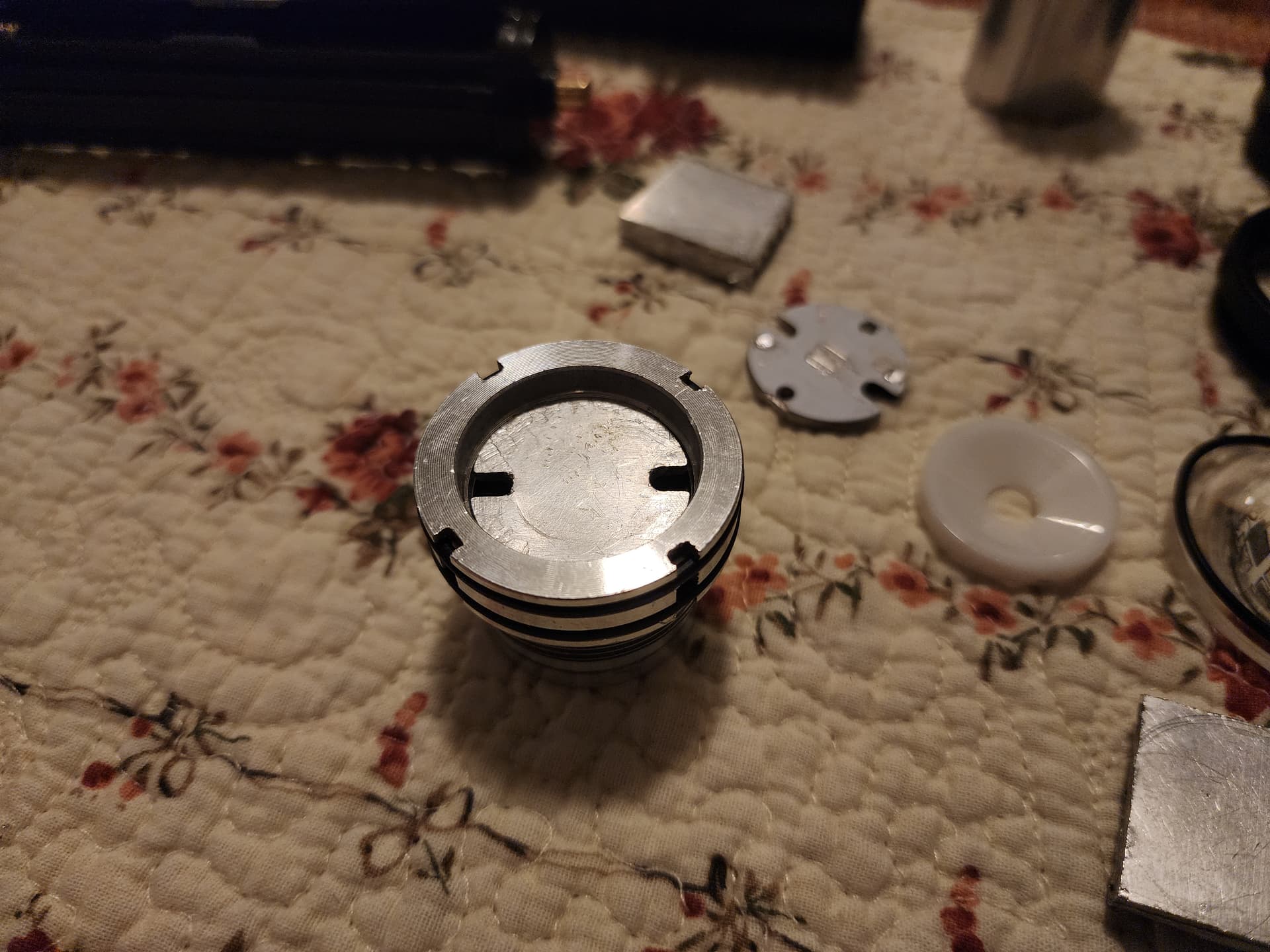
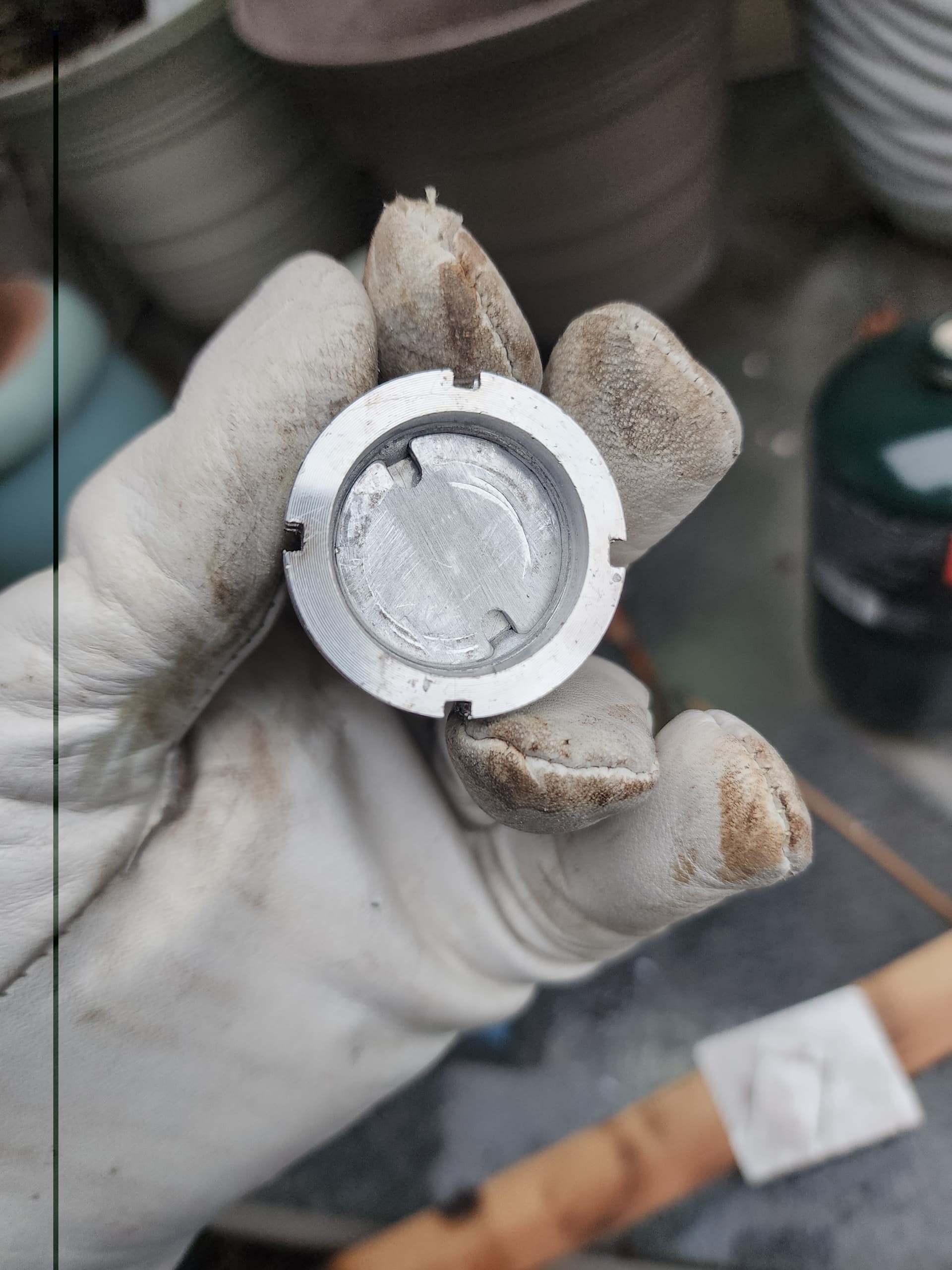
Once I was satisfied with the depth and fit up and the ground ring fit flush against the shelf (I did go a bit wide so the driver isn’t fully captured-no biggie though), on to the next item: Drilling holes for the LED wires. What a pain! Again, a drill press would have been awesome here.

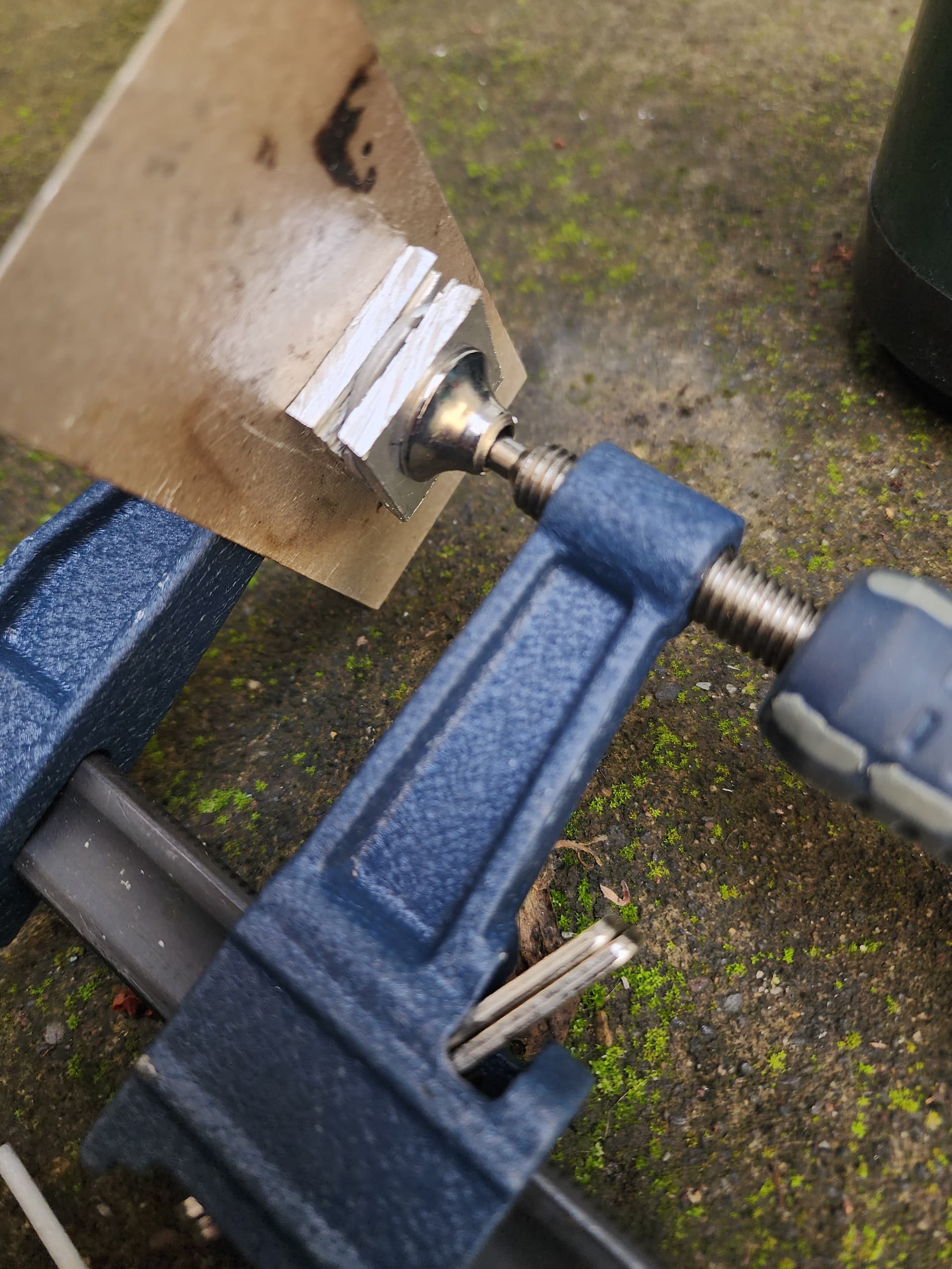
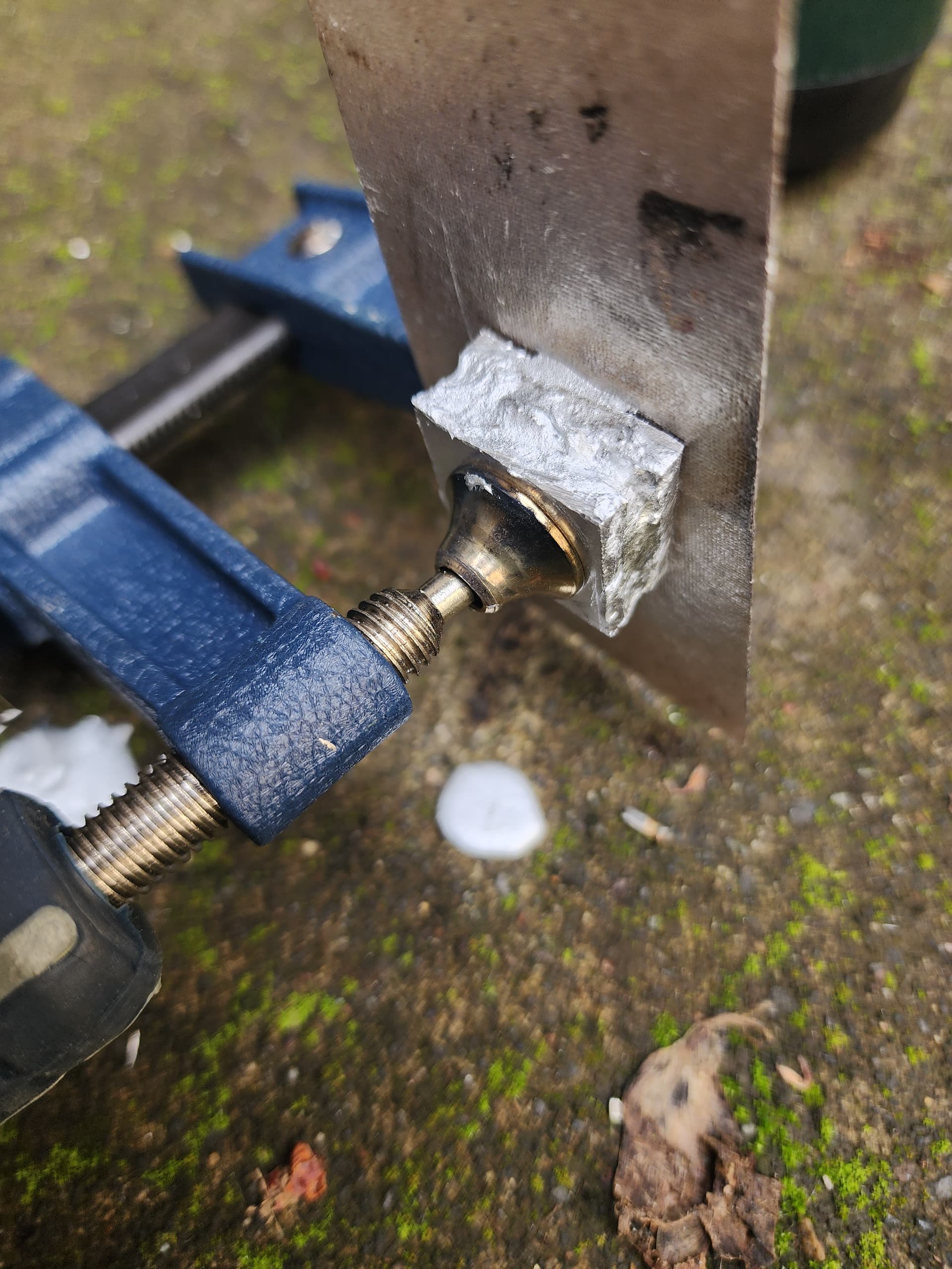
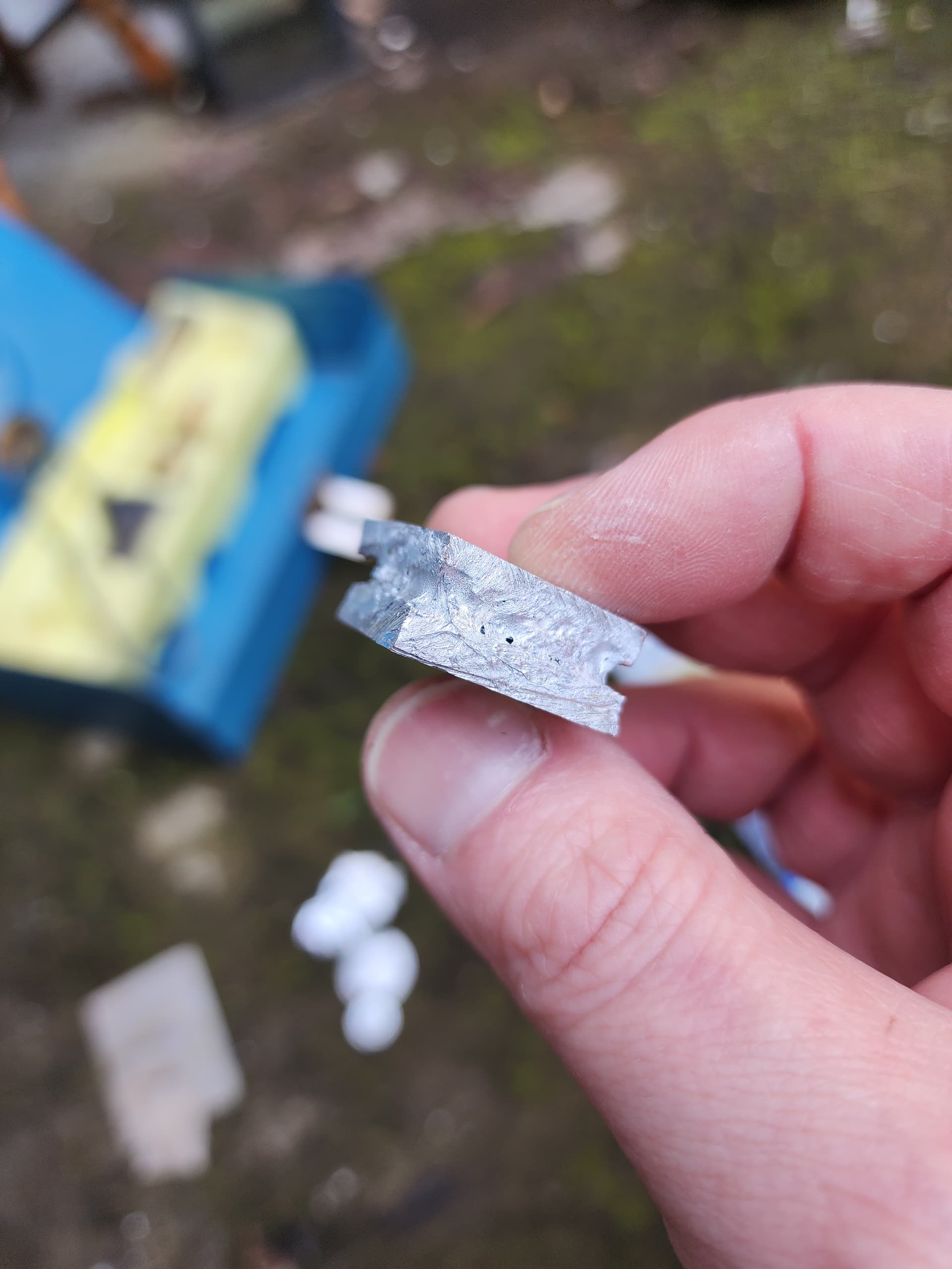
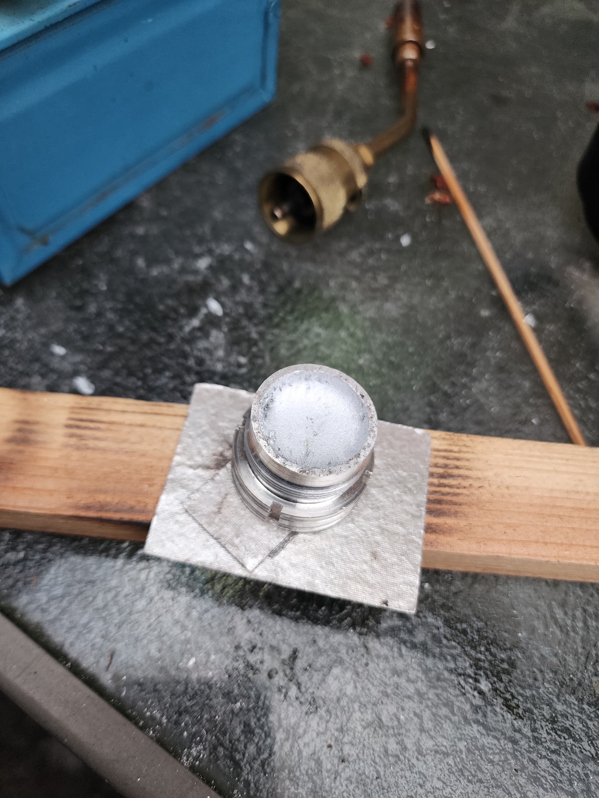
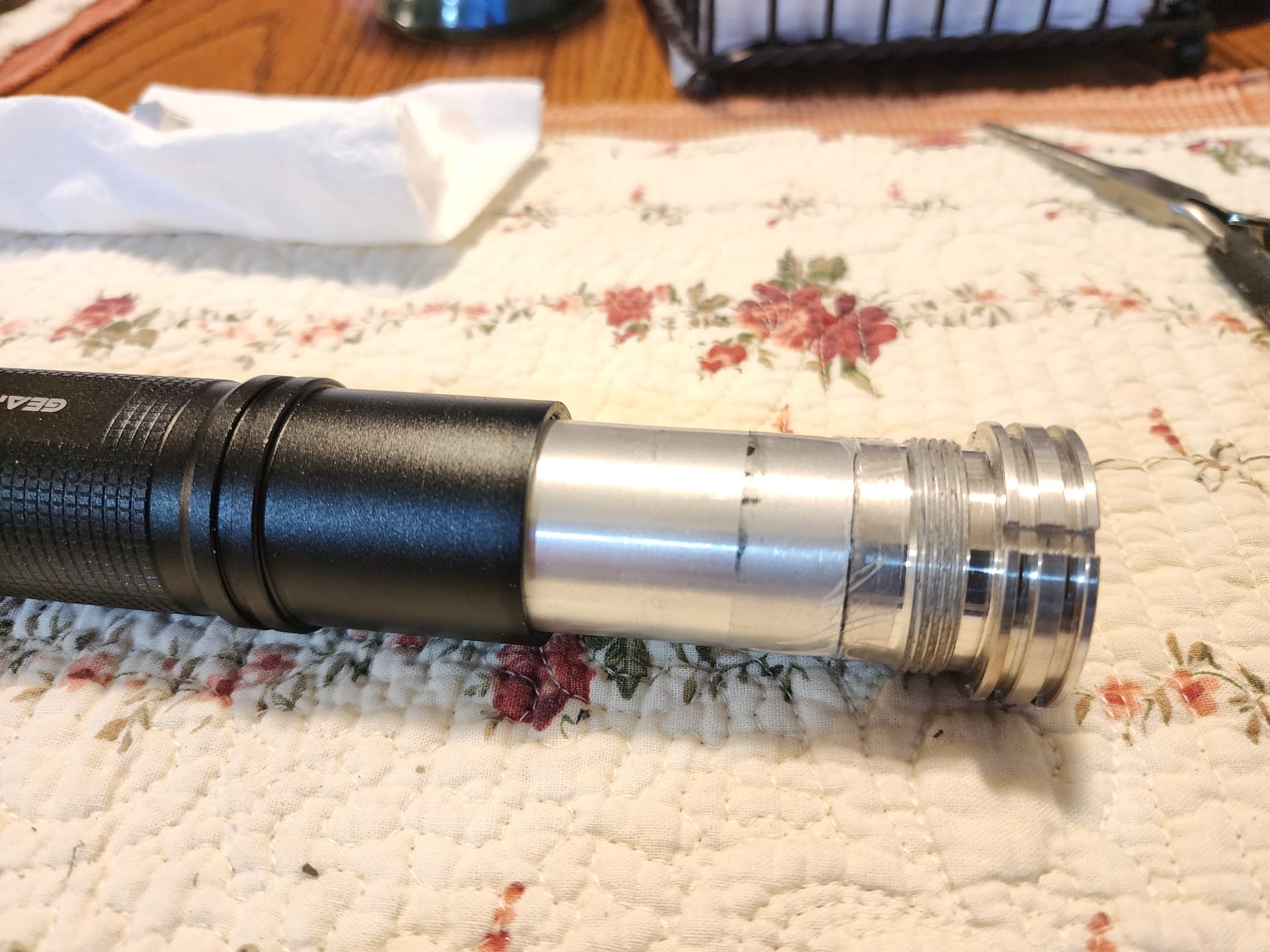
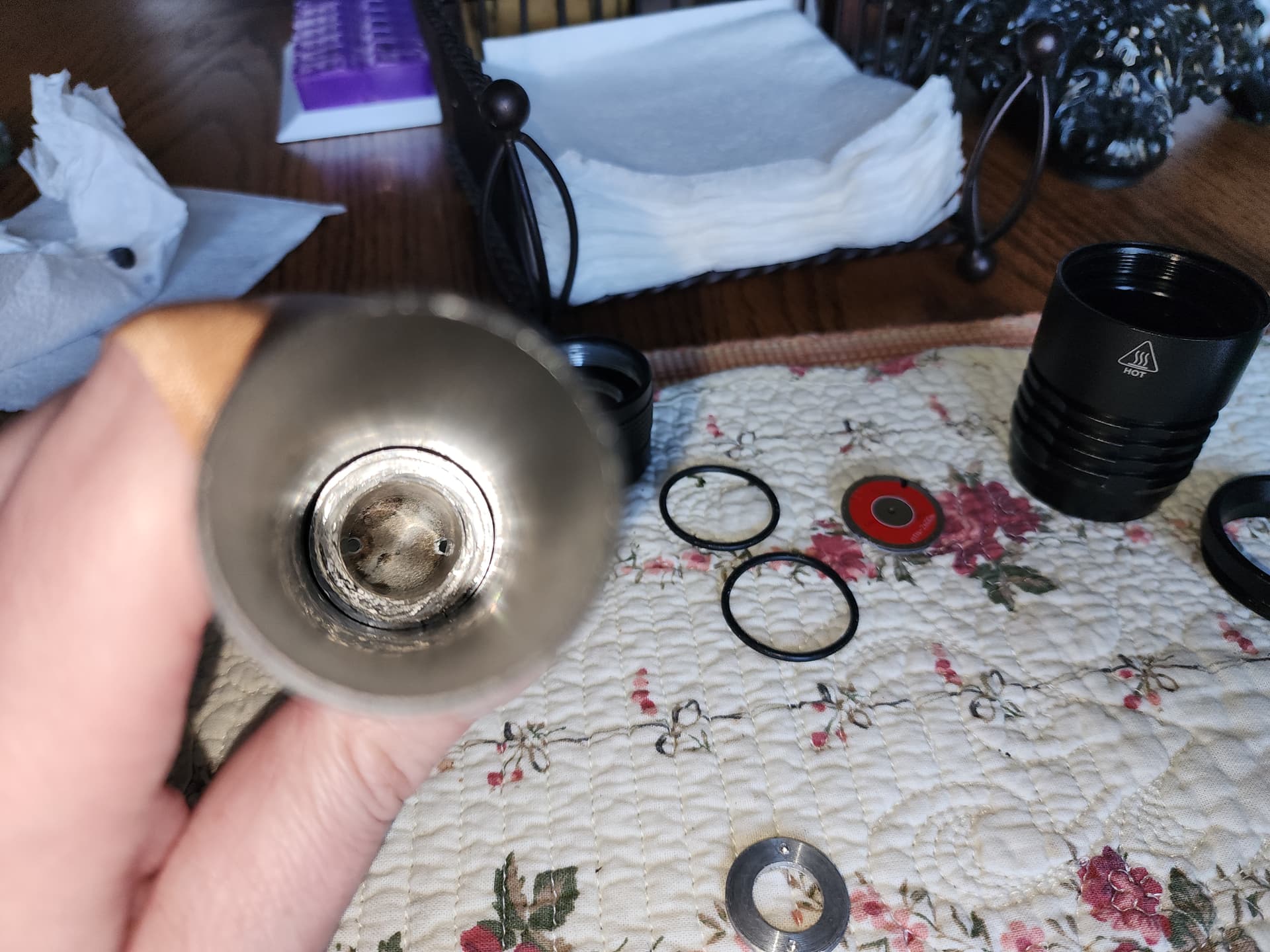
Next up: Brazing the pill extension. Step one, bevel the edges of the mating surfaces. You do this because it gives space for your filler metal to bond to the two parts being joined and creates a stronger connection.


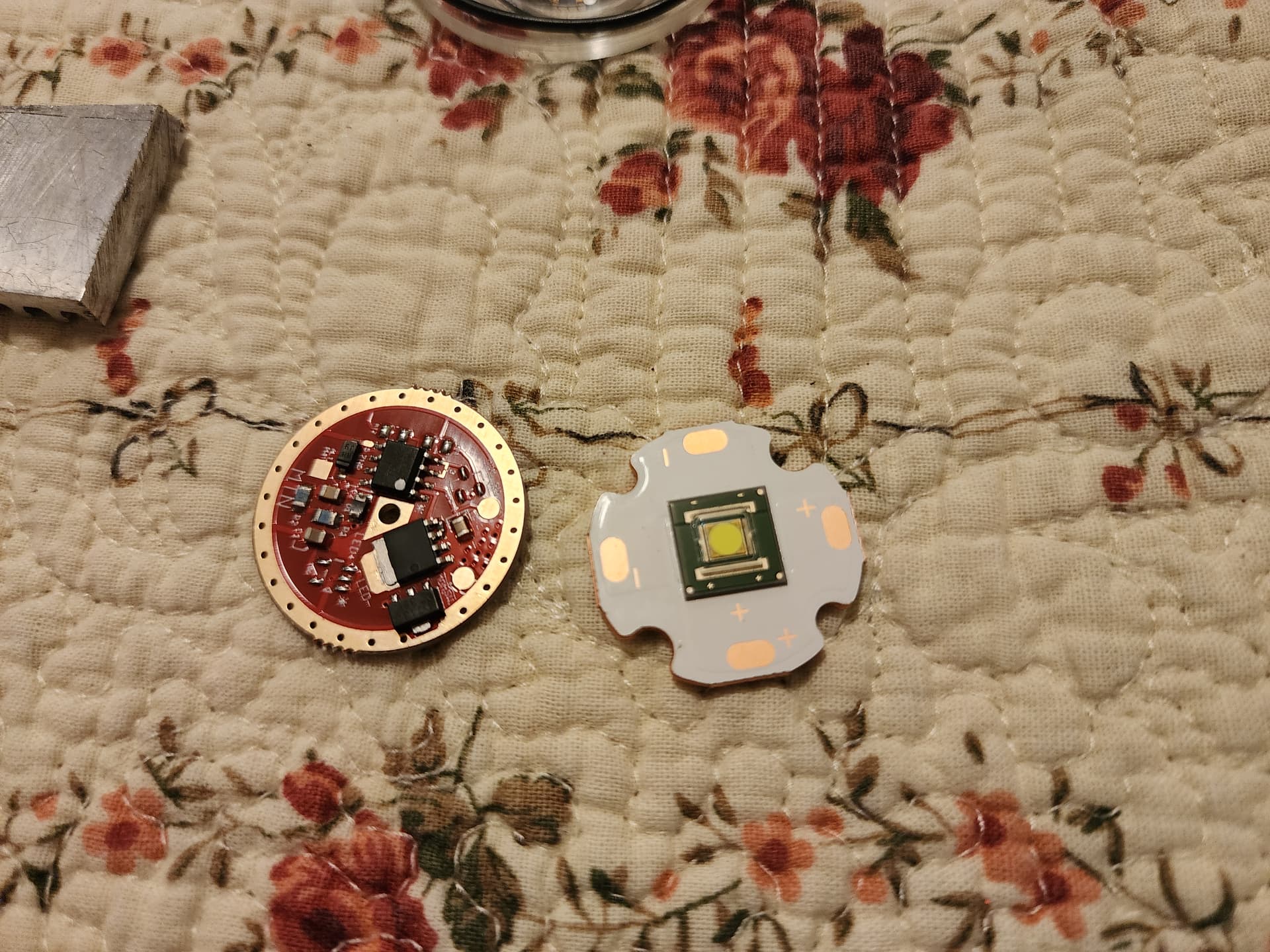
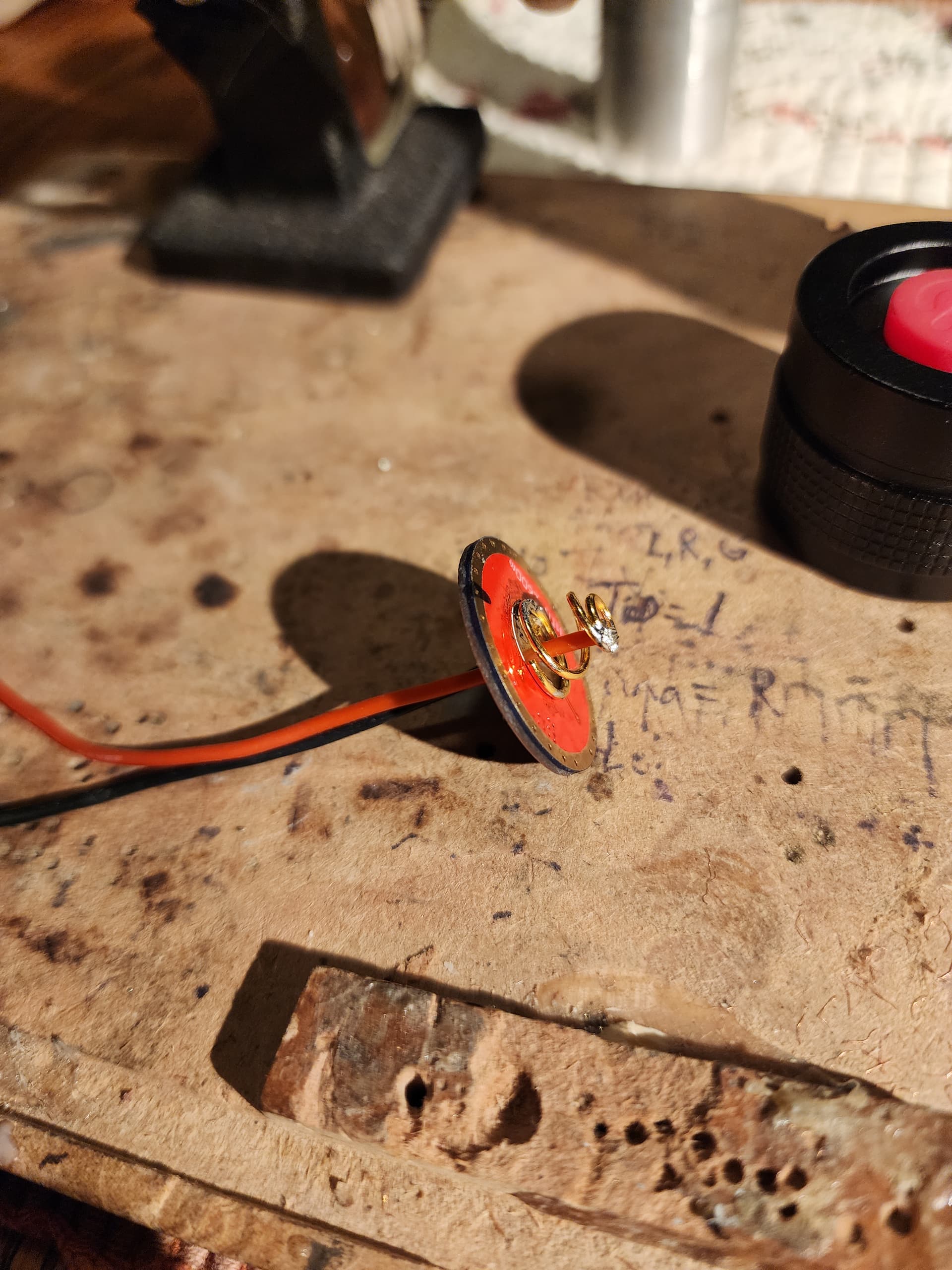
I clamped them together and got to brazing. The joint isn’t pretty, but it’s solid and makes a good connection. Another continuity check and things look good. Next, time to address the switch. I added some solder wick between the contact pad and the top of the spring. Then I prepared the driver, soldering on LED wires (22 AWG) and a positive contact spring (a Mtn Electronics BeCu short spring).


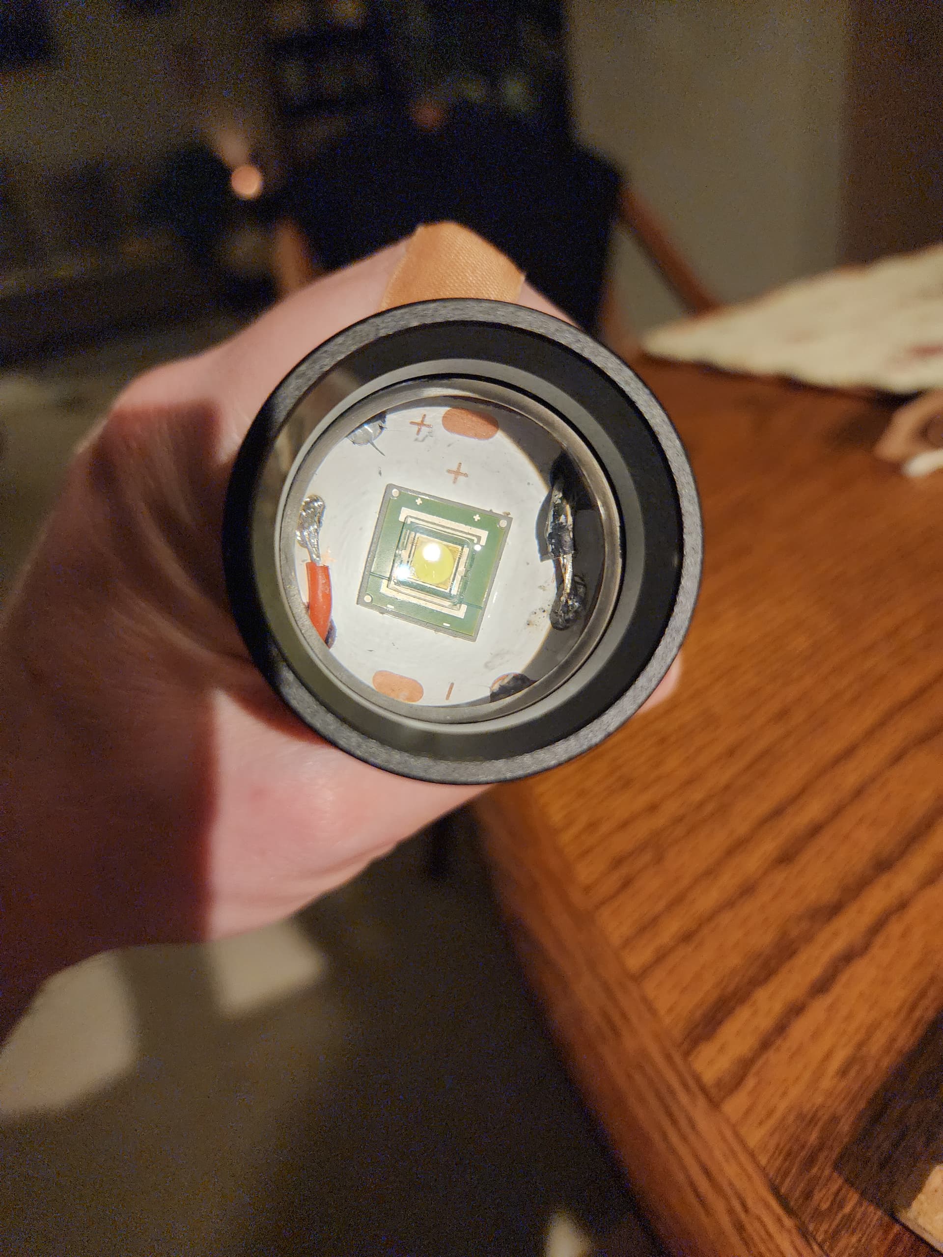
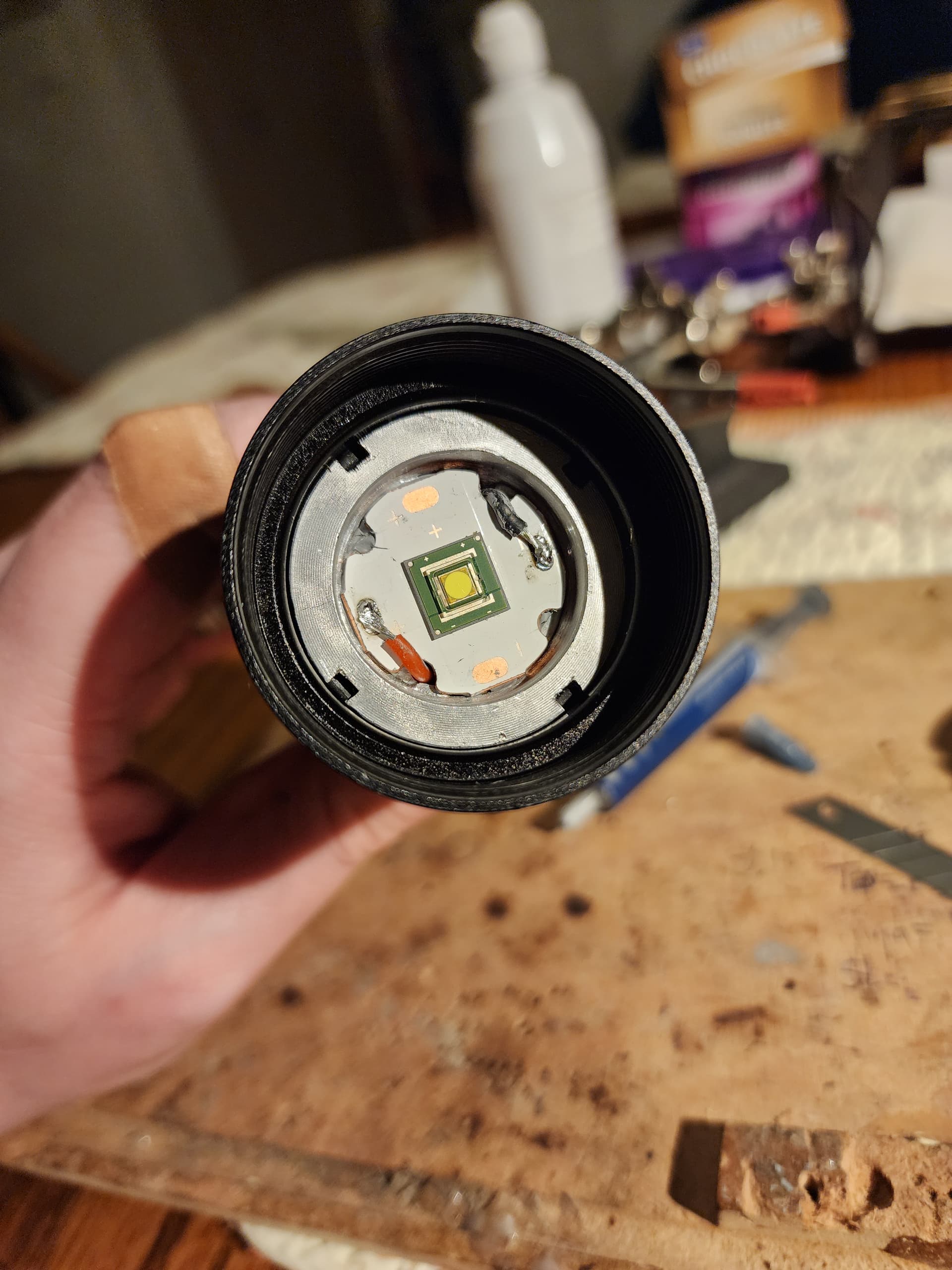
Now, on to preparing the LED shelf and adding the MCPCB with LED. The shelf wasn’t perfectly flat, and I spent a good 30 minutes or more grinding it with flat stones and sanding it to get it close. I’ll add extra thermal paste to compensate.

I seated the driver to the pill. I added kapton tape to help hold it in since it wasn’t too secure. The ground has a good connection though.

Final assembly time! Getting close. I added some thermal paste to the threaded part that threads to the tube to help with heat transfer from the pill to the tube for extra heat sinking (it works!). The long pill still fits fine in the tube even after it warped a bit from brazing.

Last steps, testing the electrical connections for shorts and assembling the head. To check for shorts, set your multimeter to continuity mode and test the connections by probing the negative (ground) and positive. If you have continuity, STOP because there’s a short and connecting a battery will either smoke the LED and/or driver (ask me how I know that one). In my case, we’re good, so on to final assembly. I tested the setup before installing putting a battery with the positive against the driver positive and jumping the battery negative to the pill with a jumper wire. If your connections are good, you’ll get light. I did (I was sweating this part) so moving on…


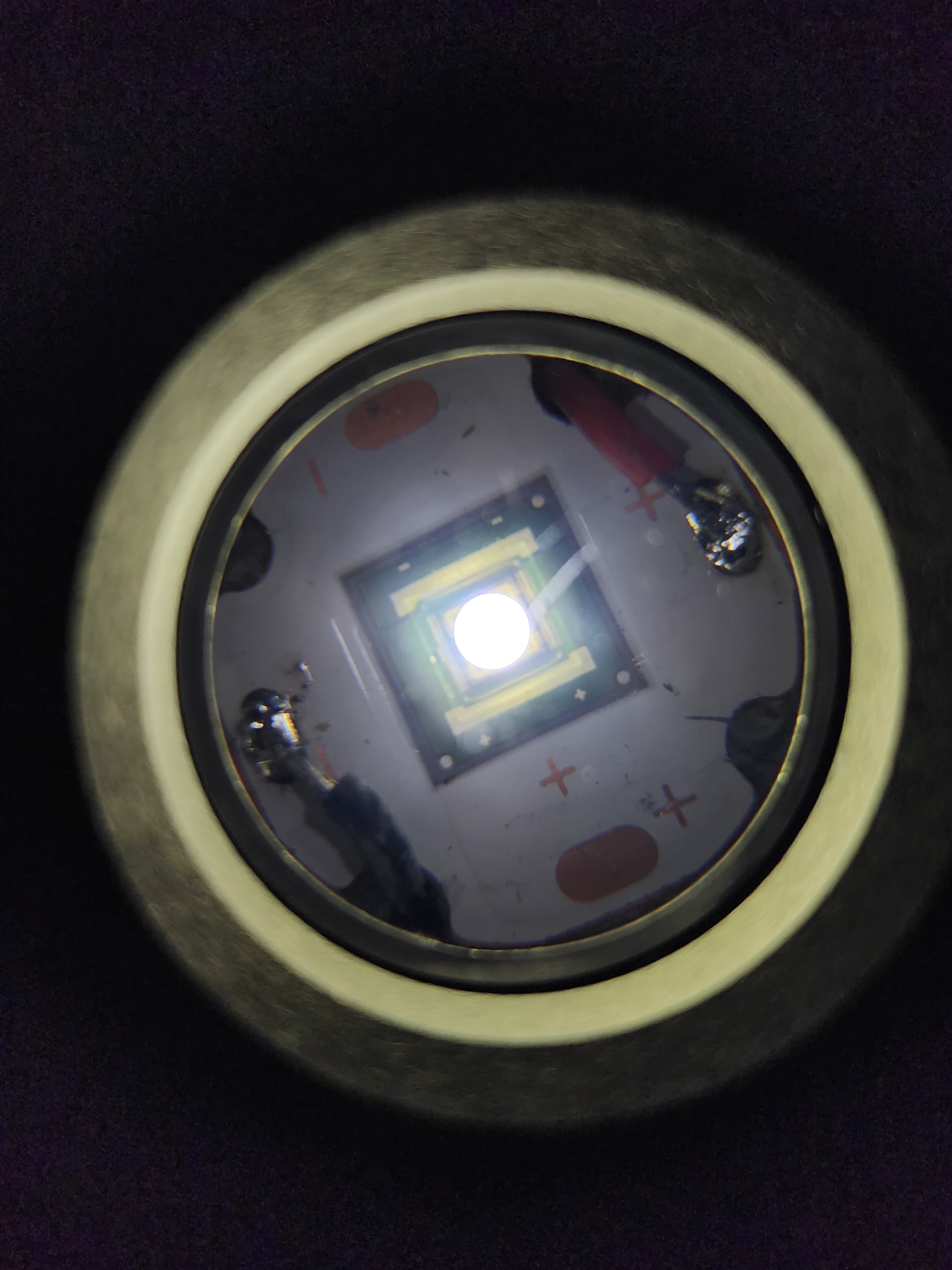
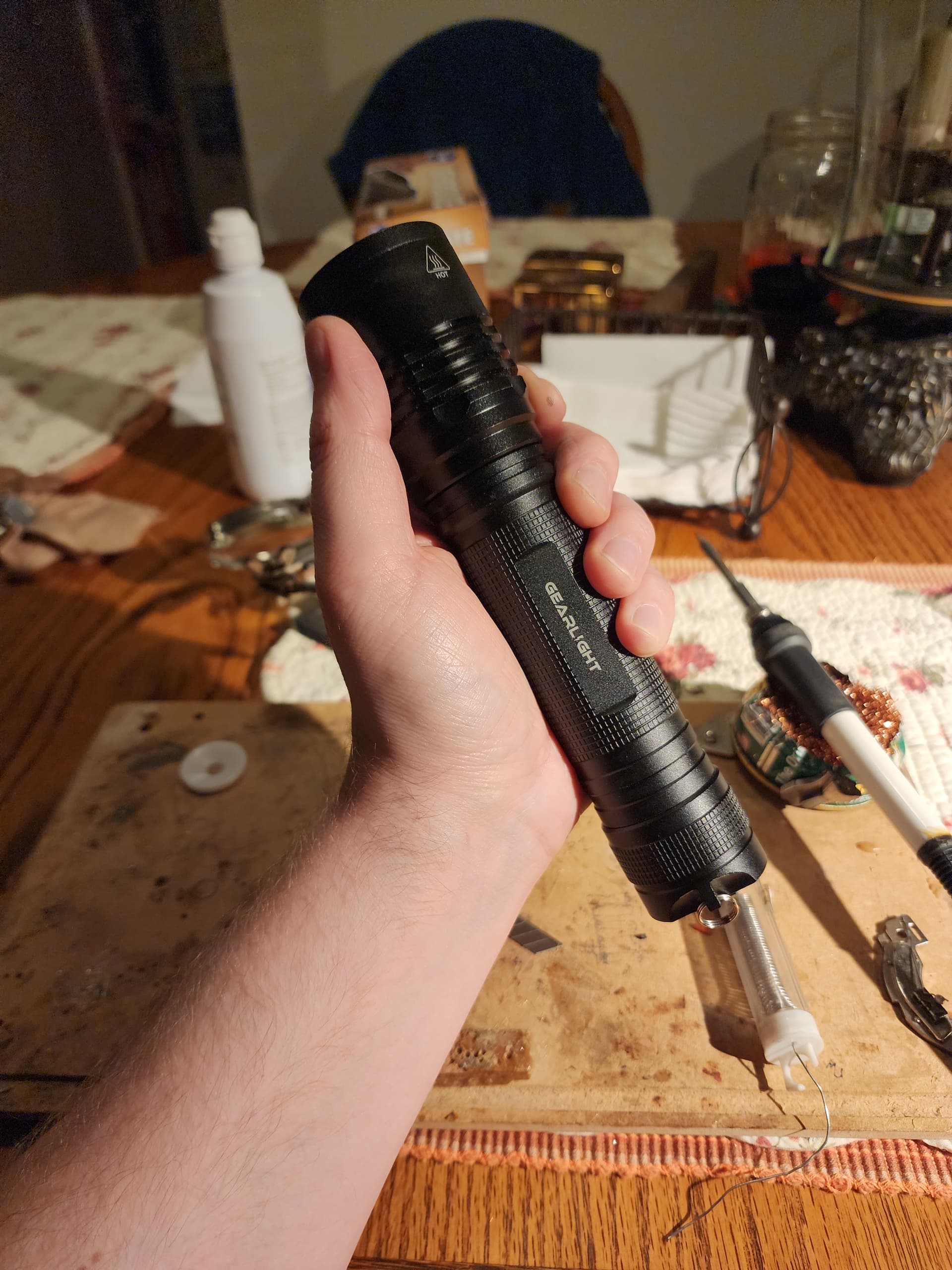
Once the head’s together, installed the optical lens, screwed on the bezel and we’re done! I omitted the plastic retainer for now. I may or may not install it depending on how the beam looks. Time to slang some photons.

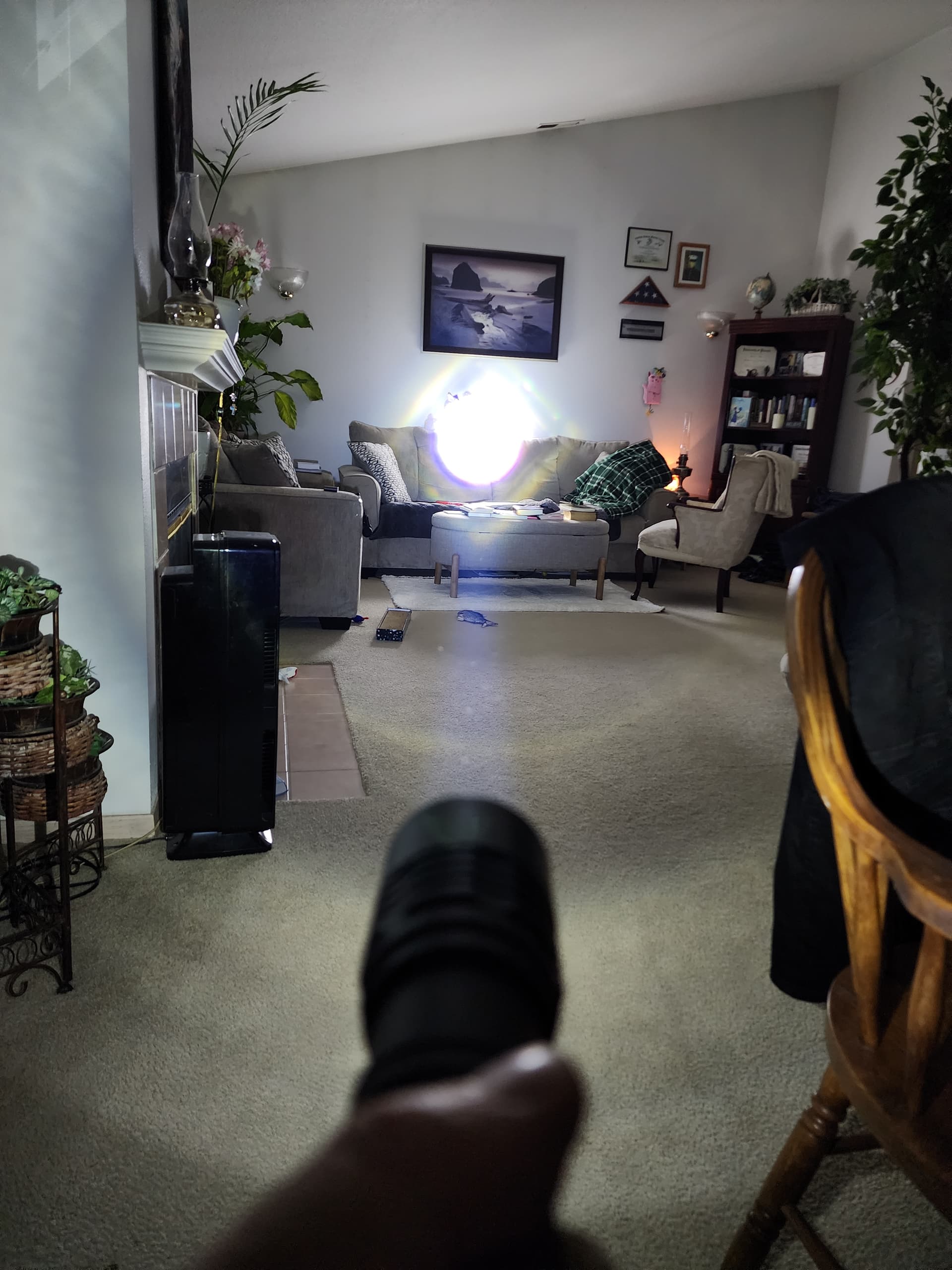
It’s super bright. This is the brightest zoomie I’ve ever seen. The hotspot is tight (round) and very intense. The spill in the zoomed out position is very bright and wide.


The tree in the below photo is about 200 meters. It easily reaches the tree.

The beam looks better than I expected without the retainer. I may paint it black and ream out the hole to fit the LED better, but that’s down the road. Overall, I’m super pleased with this project! I’ve been wanting to do it for a long time, just never had the time or motivation to do it, but I’m glad I did. I took the mostly awful Gearlight S2000 and made it into a serious flashlight that’s usable and reliable. It does get pretty warm on Turbo mode when the stepdown isn’t set (I’ll get around to it), but all that thermal mass takes a little while to heat up. The heat transfer is also okay (not great), and the tube eventually gets mighty warm.

I didn’t measure the Lumens yet, but a throw test at 5 meters netted 156,750 cd for 791 meters. That’s not on a fresh battery either!

For those interested, here’s the parts I had to buy plus cost for this (not including my time):

LED: L90 from AliExpress $6.75
Aluminum tube stock: $10 from Amazon
Driver: $24 (+ shipping, and the solder wick, springs) from Mtn Electronics
Host: Gearlight S2000 (free review sample, but they’re around $22-$24 on Amazon)
Tools: 1-3/8 step drill $14 from Amazon

Hope you enjoyed this one! It will probably be the last one I do for a looonnggg time, but who knows?

Best

4 Thanks

That’s a nice mod Sirstinky!

The costs add up for mods like this. I usually don’t include tools with my totals and sometimes I forget to take into account shipping, and thankfully my time is cheap. :grin:

Thanks for posting.

1 Thank

Thanks! I dont inculude the stuff I have on hand (wires, raw materials, soldering supplies/tools, etc).
I forget how much work these are, but it had been something I’ve wanted to do for a while. I really like this host as a zoomie because it’s big and can take the 26800, which is a sweet spot for 15 amps/about 55 watts. Plus it’s push-pull, not a twistie which I don’t like and has a big lens. I’ll have a comparison photo between the crappy S2000 and good-er S2000 soon (plus Lumens).

1 Thank

I look forward to your beam shots being used without your permission on their marketing material for the stock lights :rofl:

Cool mod, quite “old school BLF” style.

Gotta get me some of those brazing rods!

3 Thanks

Very cool Mod. Probably the first nice Gearlight :smiley:
That took some time, but very nice to see this with the whole write up!
Keep it up!

1 Thank

Yah I like the old school style like Old Lumens and DsBar, DB_customs, Matt Smith, Texas Ace, TomE l, theMiller, comfychair, and others. I got into the hobby because of their work! I niss their contributions and really hope to see more.

4 Thanks

I figure about 50 hours total in work and prep? I spent most of my Saturday finishing it up (good excuse to be outside) If I had proper tools (lathe, drill press) shave about 5 hours off that or more.

1 Thank

In case anyone’s interested, for output in my calibrated sphere:

On 100% (flood) I got 2,441 Lumens. That’s below the theoretical 3800 to 4000 the LED spec says, but this is a zoomie with aspheric lens. I’ll try with a Nightwatch xp21700 tonight.

2 Thanks