This Portable Benchtop Power Supply is not my first attempt at this. 2 1/2 years ago I tried doing this with lesser modules and the result was less than satisfactory. Both of the supplies in this link have since gavin up the ghost. They were rated at up to 3A, but couldn’t even do 1 1/2 at certain combinations of input and output voltages.
Here is a question for RD Tech or anyone else that may know.
From the instruction manual concerning connections, we a warned that connecting the supply to the output will burn up the unit.
So it would seem that if this unit is used to charge a battery, and it has no supply voltage or it is not turned on, the battery we are trying to charge could back feed into the unit and burn it up.
Is that possible?
Hi friend
good question . in fact , this is just warning that connect the module with right way. in fact, you connect a switch power supply less than 50V with output , there is no problem. but why you connect power supply on output … right ? :smiling_imp:
about the batter, now all our version of DPS and DP power supply can charge the battery. but you can’t connect it reverse polarity , ok? it will really burnt module . because we all add a similar with diode circuit , it can prevent current flowing back. don’t worry
but if you connect the battery at output , and you power off , the module will consume power of battery
thank you , hope it is useful for you
I don’t know , we did not use this … I don’t know about his quality
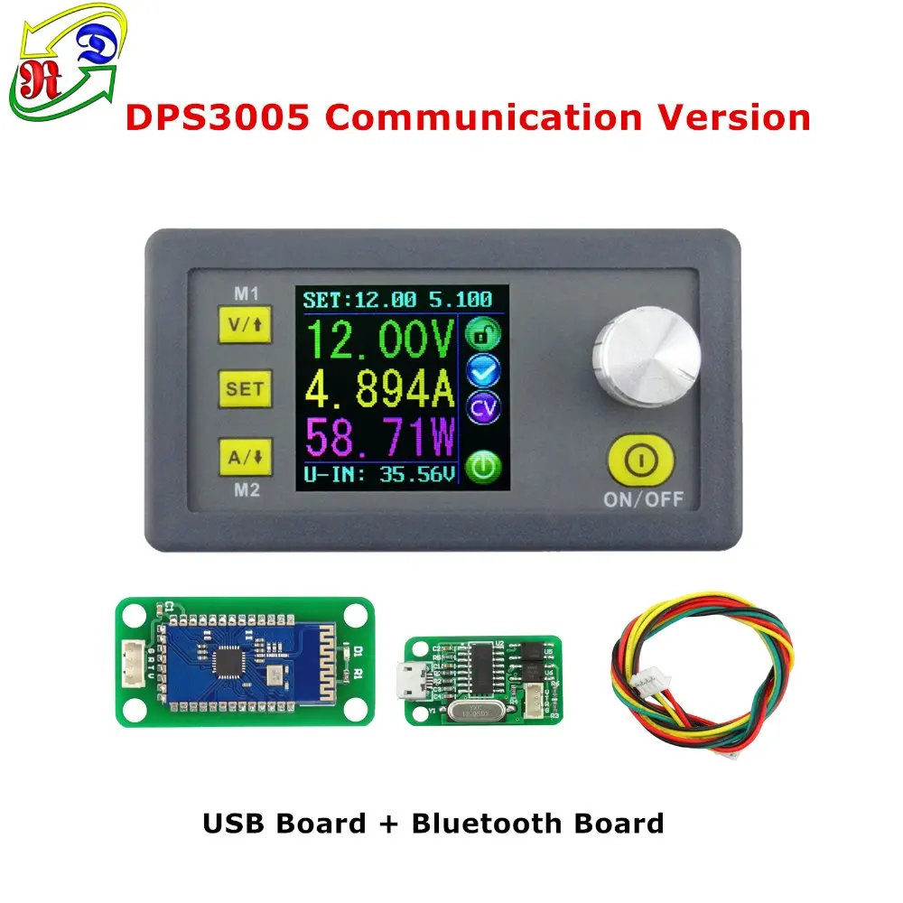
about the difference, there is a big , you can check our fuction, that one is a just naked PCB , ok? there is no any protection, there is no CC and CV .
you think a 6 usd product has no difference for 25-38 usd products?
in fact , there are many fake data for chinese products,. I know this , but our data is real ,so there are many people like this
there are many analyze on youtube and other website
Thanks RD Tech for the info. So it seems safe to use it to charge batteries so long as the battery is not connected in reverse.
Here is another question.
In the OP I mentioned that I was hoping there were no “gotchas” concerning this build, (There always seems to be some)
I came across 2. First, the system of keys and locks on the 18V, 24V, and 40V batteries that I will be using is more complicated than I originally thought. I had to cut 2 more slots in the receptacle so that each of the 3 batteries will plug in.
BUT an even bigger gotcha is that the 40V Ryobi, although will plug in, has it’s + and - terminals REVERSED.
Good thing I noticed that before it was too late.
18V Ridgid on top, 40V Ryobi on bottom.
I could still use this battery IF I installed a full wave bridge between it and the inputs of the DPS5015. the problem is though that the input current would have to pass through 2 diodes along the way. This would create a very significant power loss and reduce efficiency, quite a lot.
I am looking into using a MOSFET bridge instead. When the battery is inserted the FET’s will always be fully on, so there would be little or no power to dissipate. Using a MOSFET bridge for AC input is more complicated, but in this case it should be easy.
Anybody know of a part number that can be used?
To be fair, though, if you go another $25 and shop carefully, you can get a nice power supply — one that would have stunned my electronics shop class back in the early ’70’s, that’s for sure.
thank you for your message
Bangood reviewer? it should be the buyer of banggood, right. banggood is my reseller, the product is still ours .
about motors, fans or inductive loads, you can connect those thing , but you need to leave a roon to use , eg, our power supply max current 15A, your load rated max current is 5A, If you buy our DPS5005, the max load rated current is 1.6A , understand ?
I’m going to go out on a limb and guess that there was a reverse EMF with no bypass or snubbing diodes. If an inductive load is turned off quickly, a reverse voltage can be generated on the leads as the field collapses. If this is big enough, it will cause problems.
This is the circuit I plan on using at the input of my module, a MOSFET full wave bridge. It should have low loss as the input current does not have to pass thru any P-N junctions as they would with a simple diode bridge.
I plan on using N channel FET’s that I pull from recycled drill packs and the LM74670 can be had from Digikey.
I will still try this without using the smart diode-rectifier controllers, after all reverse connecting a DC power source is easier for the bridge to handle than an AC input.
That looks very interesting. Max input 45v. I've been playing with the idea of increasing the voltage of one of my cars from 12 to about 16v. Would be nice to inprove the efficiency of the rectification at the same time. Thank you very much for sharing that link. Look forward to seeing how this works for you.
Thank you so much , because i can add the picture directly like you, only add the link
thank you so much
if you like it, you can make a new order for this , in 3 days the price is very low
I will, but the links you provide for the product are incomplete. It looks like they were truncated when you copy and pasted them into the forum editor.
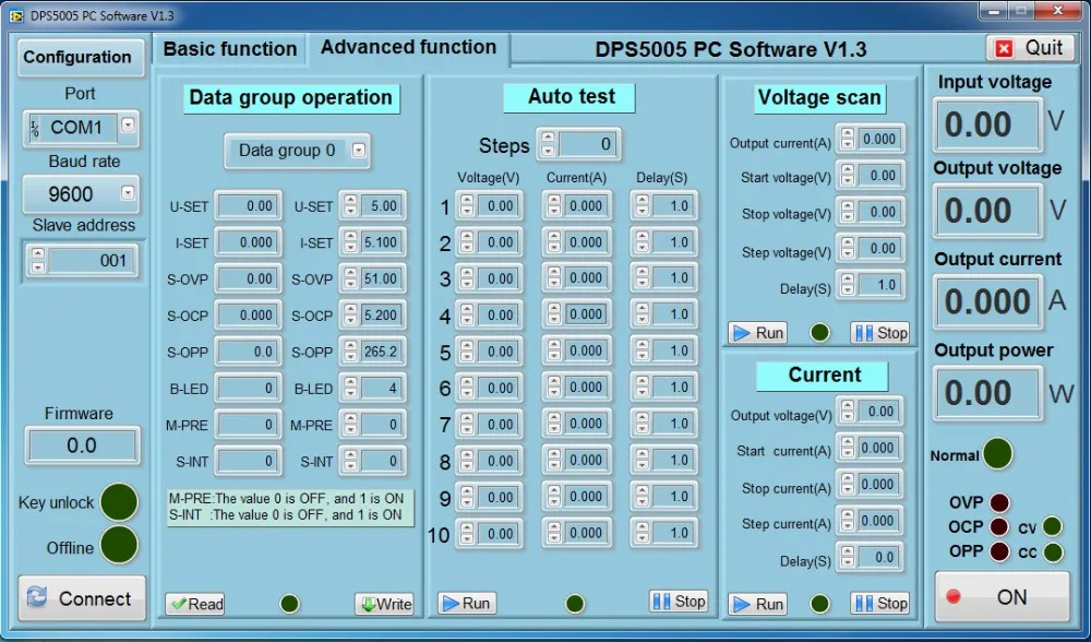
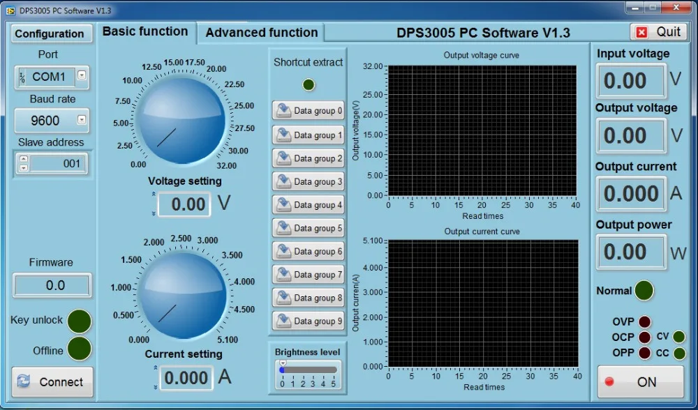
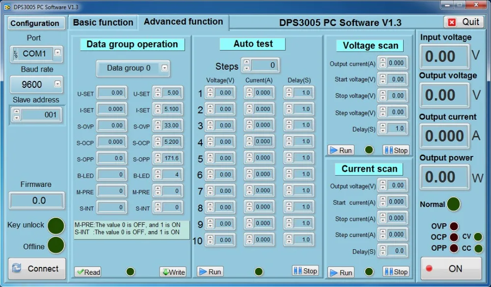
The new Comms version looks very interesting. Does it support logging to a text file over time? This would be a great selling point, writing Time, Voltage, and Current to a text file on a user selectable time period.
On a related note, I finished building out my 5015 in the turret type housing a couple weeks ago. I guess I forgot to post the pics. I wanted to have the output on the front side for easier access, so I 3D printed a small adapter to allow me to mount some Anderson Power Pole connectors in a round hole.
A step drill bit and a little file work gets me a keyed hole in the front.
A trip to the hardware store for a longer version of the right size roll pin that holds PP’s together also holds them in the adapter and the adapter in the housing.
It was a bit of a chore to get the wires inserted and neatly run inside the housing, but I only had to do it once.


